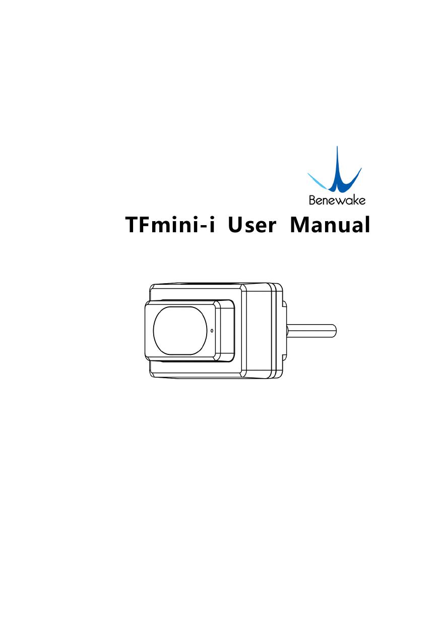
TFmini-i User Manual
�
PREFACE
Dear users:
Thank you for choosing Benewake products. For the purpose of offering better
operation experience to you, we hereby write this manual for an easier and simpler
operation of our product, hoping to better solve the common problems you may meet.
This user manual contains the relevant information on product introduction, usage and
maintenance of TFmini-i, covers the product operation introduction and common
problem solutions. Please read this manual carefully before using the product.
Remember the precautions to avoid hazards, and please follow the described steps in
the manual when using it.
If you have any problems in the process of usage, you are welcome to contact Benewake
at any time for help.
Contact details
Official website: en.benewake.com
TEL:+86-10- 57456983
Technical questions,please contact:support@benewake.com
Consult sale information or request brochure,please contact:bw@benewake.com
Headquarters Address
Benewake (Beijing) Co., Ltd.
No.3030, 3rd Floor, Independent Innovation Building, No.6 Chuangye Road, Haidian
District, Beijing, China
Copyright Statement
This User Manual is copyright © of Benewake. Please do not modify, delete or
translate the description of this manual contents without the official written
permission from Benewake.
Disclaimer
As our products are constantly improving and updating, the specifications of TFmini-i
are subject to change. Please refer to the official website for latest version.
�
CONTENTS
1 ONEVIEW ......................................................................................................................................... 1
1.1 Technical Specification .......................................................................................................... 1
1.2 Maintenance and Cleaning ................................................................................................... 2
1.3 Appearance and Installation ................................................................................................ 2
1.4 Storage ..................................................................................................................................... 3
1.5 Application .............................................................................................................................. 4
INTERFACE ....................................................................................................................................... 5
2.1 Description About Wiring Sequence .................................................................................. 5
2.2 Electrical Characteristics ....................................................................................................... 5
3 COMMUNICATION PROTOCOL .................................................................................................... 6
3.1 RS-485 Communication Protocol ........................................................................................ 6
Communication protocol.................................................................................... 6
Parameter configuration description of Modbus protocol .......................... 6
Parameter configuration .................................................................................... 8
3.2 CAN Communication Protocol .......................................................................................... 10
Communication Protocol ................................................................................. 10
CAN Communication Data Frame .................................................................. 10
CAN Bus Network ............................................................................................. 10
Parameter Configuration of CAN Communication ..................................... 11
Other Parameter Configuration ..................................................................... 12
3.2.1
3.2.2
3.2.3
3.2.4
3.2.5
2
3.1.1
3.1.2
3.1.3
�
ONEVIEW
1 ONEVIEW
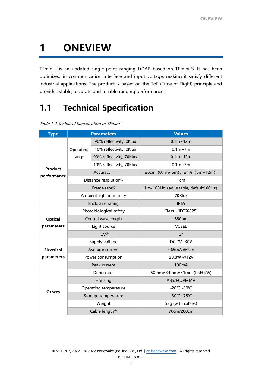
TFmini-i is an updated single-point ranging LiDAR based on TFmini-S. It has been
optimized in communication interface and input voltage, making it satisfy different
industrial applications. The product is based on the ToF (Time of Flight) principle and
provides stable, accurate and reliable ranging performance.
1.1 Technical Specification
Table 1-1 Technical Specification of TFmini-i
Type
Parameters
90% reflectivity, 0Klux
Operating
10% reflectivity, 0Klux
range
90% reflectivity, 70Klux
10% reflectivity, 70Klux
Values
0.1m~12m
0.1m~7m
0.1m~12m
0.1m~7m
Accuracy①
±6cm(0.1m~6m),±1%(6m~12m)
Distance resolution①
1cm
Frame rate②
1Hz~100Hz(adjustable, default100Hz)
Ambient light immunity
Enclosure rating
70Klux
IP65
Photobiological safety
Class1 (IEC60825)
Product
performance
Optical
parameters
Electrical
parameters
Central wavelength
Light source
FoV③
Supply voltage
Average current
Power consumption
Peak current
Dimension
Housing
Others
Operating temperature
Storage temperature
Weight
Cable length④
850nm
VCSEL
2°
DC 7V~30V
≤65mA @12V
≤0.8W @12V
100mA
50mm×34mm×41mm (L×H×W)
ABS/PC/PMMA
-20℃~60℃
-30℃~75℃
52g (with cables)
70cm/200cm
REV: 12/07/2022 · ©2022 Benewake (Beijing) Co., Ltd. | en.benewake.com | All rights reserved
BP-UM-18 A02
1
�
ONEVIEW
Note
① The detection is measured with the standard white board (90% reflectivity).
② The frame rate can be adjusted. The default value is 100Hz and the maximum
value is 100Hz, the customized frame rate should be calculated by the formula:
200/n (n is an integer with ≥ 2).
③ The angle is a theoretical value, the actual angle value has some deviation.
④ 200cm cable without terminals at the end, for the loose wire state.
1.2 Maintenance and Cleaning
Before switching on, please check if the exposed window mirror is clean, and clean
it promptly if it is dirty.
After using the device, check the optics. If it is contaminated, please clean it
promptly.
The optics should be cleaned regularly if the device be operated in a severe
environment for a long time.
Before regular cleaning, please disconnect the power. Using a soft cloth to gently
wipe the window in the same direction when the device is not operating, to avoid
repeated wiping and damage to the window mirror.
When cleaning the window, do not use alcohol to clean, so as not to damage the
window.
If you require deep cleaning of internal optics, please contact bw@benewake.com
to offer professional advice.
1.3 Appearance and Installation
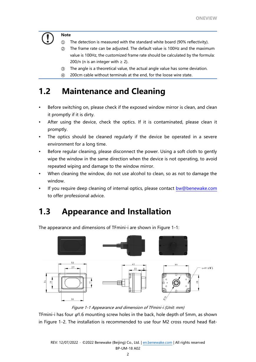
The appearance and dimensions of TFmini-i are shown in Figure 1-1:
Figure 1-1 Appearance and dimension of TFmini-i (Unit: mm)
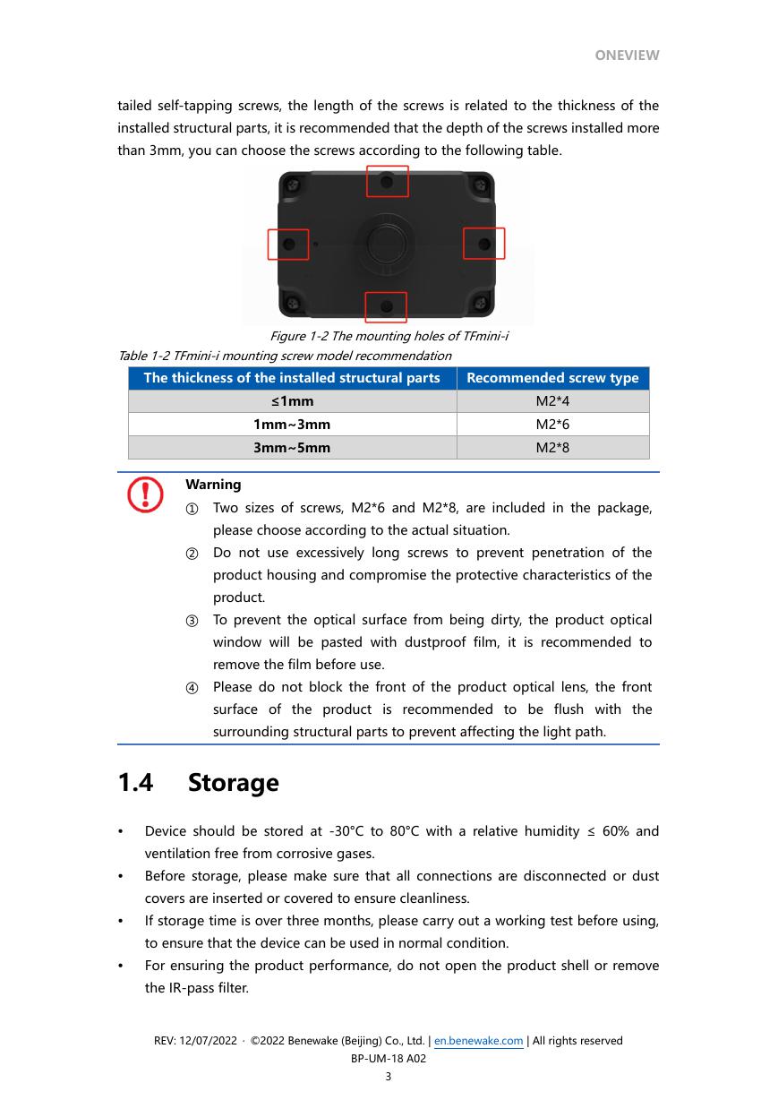
TFmini-i has four φ1.6 mounting screw holes in the back, hole depth of 5mm, as shown
in Figure 1-2. The installation is recommended to use four M2 cross round head flat-
REV: 12/07/2022 · ©2022 Benewake (Beijing) Co., Ltd. | en.benewake.com | All rights reserved
BP-UM-18 A02
2
�
tailed self-tapping screws, the length of the screws is related to the thickness of the
installed structural parts, it is recommended that the depth of the screws installed more
than 3mm, you can choose the screws according to the following table.
ONEVIEW
Figure 1-2 The mounting holes of TFmini-i
Table 1-2 TFmini-i mounting screw model recommendation
The thickness of the installed structural parts
Recommended screw type
≤1mm
1mm~3mm
3mm~5mm
M2*4
M2*6
M2*8
Warning
① Two sizes of screws, M2*6 and M2*8, are included in the package,
please choose according to the actual situation.
② Do not use excessively long screws to prevent penetration of the
product housing and compromise the protective characteristics of the
product.
③ To prevent the optical surface from being dirty, the product optical
window will be pasted with dustproof film, it is recommended to
remove the film before use.
④ Please do not block the front of the product optical lens, the front
surface of the product is recommended to be flush with the
surrounding structural parts to prevent affecting the light path.
1.4 Storage
Device should be stored at -30°C to 80°C with a relative humidity ≤ 60% and
ventilation free from corrosive gases.
Before storage, please make sure that all connections are disconnected or dust
covers are inserted or covered to ensure cleanliness.
If storage time is over three months, please carry out a working test before using,
to ensure that the device can be used in normal condition.
For ensuring the product performance, do not open the product shell or remove
the IR-pass filter.
REV: 12/07/2022 · ©2022 Benewake (Beijing) Co., Ltd. | en.benewake.com | All rights reserved
BP-UM-18 A02
3
�
ONEVIEW
1.5 Application
When using the product, please read the specifications, user manual and the
precautions mentioned in the user manual in detail to ensure that the product is used
within the rated specifications. The product is designed for use in the following
scenarios:
Robot
Intelligent Transportation
Intelligent Device
UAV
Other Industrial Products
If you use the product beyond the above application scope, please carefully evaluate
whether the reliability requirements of the product to be applied match this product, or
contact Benewake at any time to assist in solving it.
REV: 12/07/2022 · ©2022 Benewake (Beijing) Co., Ltd. | en.benewake.com | All rights reserved
BP-UM-18 A02
4
�
2
INTERFACE
INTERFACE
2.1 Description About Wiring Sequence
Terminal model: MH1.25-7P-W/B, size of single wire is AWG26, diameter of single wire
is 0.404mm, cross-sectional area is 0.129mm2, which show in Table 2-1.
Figure 2-1 TFmini-i external wiring connector and wiring sequence
Table 2-1 The Function Description of Each Wire
Pin
Wiring color
Function
Red
VCC
1
2
3
4
5
6
7
Comment
Power supply
White/Yellow
RS485-B/CAN_L
RS485-B/CAN bus
Green
N/A
RS485-A/CAN_H
RS485-A/CAN bus
N/A
N/A
Blue/Orange
UART_RXD
UART receive (Debug)
Brown
Black
UART_TXD
UART transmit (Debug)
GND
Ground
Warning
① The hardware of RS-485 and CAN is different;
② Do not mix UART cable with RS485 or CAN bus, otherwise it will cause
damage of MCU.
③ TFmini-i with RS-485 interface does not support UART debugging pins.
2.2
Electrical Characteristics
Table 2-2 Main Electrical Parameters of TFmini-i
Parameter
Supply voltage
Average current
Peak current
Values
DC 7V~30V
≤65mA@12V
100mA
Average power consumption
≤0.8W@12V
REV: 12/07/2022 · ©2022 Benewake (Beijing) Co., Ltd. | en.benewake.com | All rights reserved
BP-UM-18 A02
5
�



 V2版本原理图(Capacitive-Fingerprint-Reader-Schematic_V2).pdf
 摄像头工作原理.doc
 VL53L0X简要说明(En.FLVL53L00216).pdf
 原理图(DVK720-Schematic).pdf
 原理图(Pico-Clock-Green-Schdoc).pdf
 原理图(RS485-CAN-HAT-B-schematic).pdf
 File:SIM7500_SIM7600_SIM7800 Series_SSL_Application Note_V2.00.pdf
 ADS1263(Ads1262).pdf
 原理图(Open429Z-D-Schematic).pdf
 用户手册(Capacitive_Fingerprint_Reader_User_Manual_CN).pdf
 CY7C68013A(英文版)(CY7C68013A).pdf
 TechnicalReference_Dem.pdf