1 Features
2 Applications
3 Description
Table of Contents
4 Revision History
5 Device Comparison
6 Pin Configuration and Functions
7 Specifications
7.1 Absolute Maximum Ratings
7.2 ESD Ratings
7.3 Recommended Operating Conditions
7.4 Thermal Information
7.5 Electrical Characteristics
7.6 Timing Requirements: Serial Interface
7.7 Switching Characteristics: Serial Interface
7.8 Typical Characteristics
8 Parameter Measurement Information
8.1 Offset Temperature Drift Measurement
8.2 Gain Temperature Drift Measurement
8.3 Common-Mode Rejection Ratio Measurement
8.4 Power-Supply Rejection Ratio Measurement
8.5 Crosstalk Measurement (ADS1263)
8.6 Reference-Voltage Temperature-Drift Measurement
8.7 Reference-Voltage Thermal-Hysteresis Measurement
8.8 Noise Performance
9 Detailed Description
9.1 Overview
9.2 Functional Block Diagram
9.3 Feature Description
9.3.1 Multifunction Analog Inputs
9.3.2 Analog Input Description
9.3.2.1 ESD Diode
9.3.2.2 Input Multiplexer
9.3.3 Sensor Bias
9.3.4 Temperature Sensor
9.3.5 Power-Supply Monitor
9.3.6 PGA
9.3.7 PGA Voltage Overrange Monitors
9.3.7.1 PGA Differential Output Monitor
9.3.7.2 PGA Absolute Output-Voltage Monitor
9.3.8 ADC Reference Voltage
9.3.8.1 Internal Reference
9.3.8.2 External Reference
9.3.8.3 Power-Supply Reference
9.3.8.4 Low-Reference Monitor
9.3.8.5 Sensor-Excitation Current Sources (IDAC1 and IDAC2)
9.3.8.6 Level-Shift Voltage
9.3.9 ADC1 Modulator
9.3.10 Digital Filter
9.3.10.1 Sinc Filter Mode
9.3.10.2 FIR Filter
9.3.10.3 50-Hz and 60-Hz Line Cycle Rejection
9.3.11 General-Purpose Input/Output (GPIO)
9.3.12 Test DAC (TDAC)
9.3.13 ADC2 (ADS1263)
9.3.13.1 ADC2 Inputs
9.3.13.2 ADC2 PGA
9.3.13.3 ADC2 Reference
9.3.13.4 ADC2 Modulator
9.3.13.5 ADC2 Digital Filter
9.4 Device Functional Modes
9.4.1 Conversion Control
9.4.1.1 Continuous Conversion Mode
9.4.1.2 Pulse Conversion Mode
9.4.1.3 ADC2 Conversion Control (ADS1263)
9.4.2 Conversion Latency
9.4.3 Programmable Time Delay
9.4.4 Serial Interface
9.4.4.1 Chip Select (CS)
9.4.4.2 Serial Clock (SCLK)
9.4.4.3 Data Input (DIN)
9.4.4.4 Data Output/Data Ready (DOUT/DRDY)
9.4.4.5 Serial Interface Autoreset
9.4.5 Data Ready Pin (DRDY)
9.4.6 Conversion Data Software Polling
9.4.7 Read Conversion Data
9.4.7.1 Read Data Direct (ADC1 Only)
9.4.7.2 Read Data by Command
9.4.7.3 Data-Byte Sequence
9.4.8 ADC Clock Modes
9.4.8.1 Internal Oscillator
9.4.8.2 External Clock
9.4.8.3 Crystal Oscillator
9.4.9 Calibration
9.4.9.1 Offset and Full-Scale Calibration
9.4.9.2 ADC1 Offset Self-Calibration (SFOCAL1)
9.4.9.3 ADC1 Offset System Calibration (SYOCAL1)
9.4.9.4 ADC2 Offset Self-Calibration ADC2 (SFOCAL2)
9.4.9.5 ADC2 Offset System Calibration ADC2 (SYOCAL2)
9.4.9.6 ADC1 Full-Scale System Calibration (SYGCAL1)
9.4.9.7 ADC2 Full-Scale System Calibration ADC2 (SYGCAL2)
9.4.9.8 Calibration Command Procedure
9.4.9.9 User Calibration Procedure
9.4.10 Reset
9.4.10.1 Power-On Reset (POR)
9.4.10.2 RESET/PWDN Pin
9.4.10.3 Reset by Command
9.4.11 Power-Down Mode
9.4.12 Chop Mode
9.5 Programming
9.5.1 NOP Command
9.5.2 RESET Command
9.5.3 START1, STOP1, START2, STOP2 Commands
9.5.4 RDATA1, RDATA2 Commands
9.5.5 SYOCAL1, SYGCAL1, SFOCAL1, SYOCAL2, SYGCAL2, SFOCAL2 Commands
9.5.6 RREG Command
9.5.7 WREG Command
9.6 Register Maps
9.6.1 Device Identification Register (address = 00h) [reset = x]
9.6.2 Power Register (address = 01h) [reset = 11h]
9.6.3 Interface Register (address = 02h) [reset = 05h]
9.6.4 Mode0 Register (address = 03h) [reset = 00h]
9.6.5 Mode1 Register (address = 04h) [reset = 80h]
9.6.6 Mode2 Register (address = 05h) [reset = 04h]
9.6.7 Input Multiplexer Register (address = 06h) [reset = 01h]
9.6.8 Offset Calibration Registers (address = 07h, 08h, 09h) [reset = 00h, 00h, 00h]
9.6.9 Full-Scale Calibration Registers (address = 0Ah, 0Bh, 0Ch) [reset = 40h, 00h, 00h]
9.6.10 IDACMUX Register (address = 0Dh) [reset = BBh]
9.6.11 IDACMAG Register (address = 0Eh) [reset = 00h]
9.6.12 REFMUX Register (address = 0Fh) [reset = 00h]
9.6.13 TDACP Control Register (address = 10h) [reset = 00h]
9.6.14 TDACN Control Register (address = 11h) [reset = 00h]
9.6.15 GPIO Connection Register (address = 12h) [reset = 00h]
9.6.16 GPIO Direction Register (address = 13h) [reset = 00h]
9.6.17 GPIO Data Register (address = 14h) [reset = 00h]
9.6.18 ADC2 Configuration Register (address = 15h) [reset = 00h]
9.6.19 ADC2 Input Multiplexer Register (address = 16h) [reset = 01h]
9.6.20 ADC2 Offset Calibration Registers (address = 17h, 18h) [reset = 00h, 00h]
9.6.21 ADC2 Full-Scale Calibration Registers (address = 19h, 1Ah) [reset = 00h, 40h]
10 Application and Implementation
10.1 Application Information
10.1.1 Isolated (or Floated) Inputs
10.1.2 Single-Ended Measurements
10.1.3 Differential Measurements
10.1.4 Input Range
10.1.5 Input Filtering
10.1.5.1 Aliasing
10.1.6 Input Overload
10.1.7 Unused Inputs and Outputs
10.1.8 Voltage Reference
10.1.9 Serial Interface Connections
10.2 Typical Applications
10.2.1 3-Wire RTD Measurement with Lead-Wire Compensation
10.2.1.1 Design Requirements
10.2.1.2 Detailed Design Procedure
10.2.1.3 Application Curve
10.3 Dos and Don'ts
10.4 Initialization Setup
11 Power-Supply Recommendations
11.1 Power-Supply Decoupling
11.2 Analog Power-Supply Clamp
11.3 Power-Supply Sequencing
12 Layout
12.1 Layout Guidelines
12.2 Layout Example
13 Device and Documentation Support
13.1 Related Links
13.2 Community Resources
13.3 Trademarks
13.4 Electrostatic Discharge Caution
13.5 Glossary
14 Mechanical, Packaging, and Orderable Information

.pdf-第1页.jpg")
.pdf-第2页.jpg")
.pdf-第3页.jpg")
.pdf-第4页.jpg")
.pdf-第5页.jpg")
.pdf-第6页.jpg")
.pdf-第7页.jpg")
.pdf-第8页.jpg")
 V2版本原理图(Capacitive-Fingerprint-Reader-Schematic_V2).pdf
 摄像头工作原理.doc
 VL53L0X简要说明(En.FLVL53L00216).pdf
 原理图(DVK720-Schematic).pdf
 原理图(Pico-Clock-Green-Schdoc).pdf
 原理图(RS485-CAN-HAT-B-schematic).pdf
 File:SIM7500_SIM7600_SIM7800 Series_SSL_Application Note_V2.00.pdf
 原理图(Open429Z-D-Schematic).pdf
 用户手册(Capacitive_Fingerprint_Reader_User_Manual_CN).pdf
 CY7C68013A(英文版)(CY7C68013A).pdf
 TechnicalReference_Dem.pdf
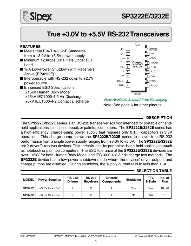 SP3232EEN 手册(SP3232EEN).pdf
 23-S4P+与IRC5P的差别-ABB喷涂机器人培训.pdf