logo资料库

ESP32-C6 Series Datasheet(英文)(ESP32-C6_Series_Datasheet).pdf

第1页 / 共72页
第2页 / 共72页
第3页 / 共72页
第4页 / 共72页
第5页 / 共72页
第6页 / 共72页
第7页 / 共72页
第8页 / 共72页
资料共72页,剩余部分请下载后查看
Product Overview
Features
Applications
1 ESP32-C6 Series Comparison
1.1 Nomenclature
1.2 Comparison
2 Pins
2.1 Pin Layout
2.2 Pin Overview
2.3 IO Pins
2.3.1 IO MUX and GPIO Pin Functions
2.3.2 LP IO MUX Functions
2.3.3 Analog Functions
2.3.4 Restrictions for GPIOs and LP GPIOs
2.4 Analog Pins
2.5 Power Supply
2.5.1 Power Pins
2.5.2 Power Scheme
2.5.3 Chip Power-up and Reset
2.6 Strapping Pins
2.6.1 SDIO Sampling and Driving Clock Edge Control
2.6.2 Chip Boot Mode Control
2.6.3 ROM Messages Printing Control
2.6.4 JTAG Signal Source Control
2.7 Pin Mapping Between Chip and Flash
3 Functional Description
3.1 CPU and Memory
3.1.1 HP CPU
3.1.2 LP CPU
3.1.3 Internal Memory
3.1.4 Off-package Flash
3.1.5 Address Mapping Structure
3.1.6 Cache
3.1.7 TEE Controller
3.1.8 Access Permission Management (APM)
3.1.9 Timeout Protection
3.2 System Clocks
3.2.1 CPU Clock
3.2.2 Low-Power Clocks
3.3 Analog Peripherals
3.3.1 Analog-to-Digital Converter (ADC)
3.3.2 Temperature Sensor
3.4 Digital Peripherals
3.4.1 Universal Asynchronous Receiver Transmitter (UART)
3.4.2 Serial Peripheral Interface (SPI)
3.4.3 I2C Interface
3.4.4 I2S Interface
3.4.5 Pulse Count Controller (PCNT)
3.4.6 USB Serial/JTAG Controller
3.4.7 TWAI Controller
3.4.8 SDIO 2.0 Slave Controller
3.4.9 LED PWM Controller
3.4.10 Motor Control PWM (MCPWM)
3.4.11 Remote Control Peripheral
3.4.12 Parallel IO (PARLIO) Controller
3.4.13 General DMA Controller (GDMA)
3.4.14 Event Task Matrix (ETM)
3.5 Radio
3.5.1 2.4 GHz Receiver
3.5.2 2.4 GHz Transmitter
3.5.3 Clock Generator
3.6 Wi-Fi
3.6.1 Wi-Fi Radio and Baseband
3.6.2 Wi-Fi MAC
3.6.3 Networking Features
3.7 Bluetooth LE
3.7.1 Bluetooth LE PHY
3.7.2 Bluetooth LE Link Controller
3.8 802.15.4
3.8.1 802.15.4 PHY
3.8.2 802.15.4 MAC
3.9 Low Power Management
3.10 Timers
3.10.1 System Timer
3.10.2 General Purpose Timers
3.10.3 Watchdog Timers
3.11 Cryptography/Security Components
3.11.1 AES Accelerator (AES)
3.11.2 ECC Accelerator (ECC)
3.11.3 HMAC Accelerator (HMAC)
3.11.4 RSA Accelerator (RSA)
3.11.5 SHA Accelerator (SHA)
3.11.6 Digital Signature (DS)
3.11.7 External Memory Encryption and Decryption (XTS_AES)
3.11.8 Random Number Generator (RNG)
3.12 Peripheral Pin Configurations
4 Electrical Characteristics
4.1 Absolute Maximum Ratings
4.2 Recommended Power Supply Characteristics
4.3 VDD_SPI Output Characteristics
4.4 DC Characteristics (3.3 V, 25 °C)
4.5 ADC Characteristics
4.6 Current Consumption
4.6.1 RF Current Consumption in Active Mode
4.6.2 Current Consumption in Other Modes
4.7 Reliability
5 RF Characteristics
5.1 Wi-Fi Radio
5.1.1 Wi-Fi RF Transmitter (TX) Characteristics
5.1.2 Wi-Fi RF Receiver (RX) Characteristics
5.2 Bluetooth LE Radio
5.2.1 Bluetooth LE RF Transmitter (TX) Characteristics
5.2.2 Bluetooth LE RF Receiver (RX) Characteristics
5.3 802.15.4 Radio
5.3.1 802.15.4 RF Transmitter (TX) Characteristics
5.3.2 802.15.4 RF Receiver (RX) Characteristics
6 Packaging
7 Related Documentation and Resources
Appendix A – ESP32-C6 Consolidated Pin Overview
Revision History
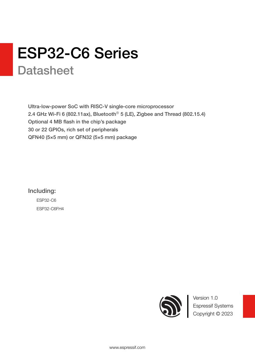
ESP32-C6 Series Datasheet Ultra-low-power SoC with RISC-V single-core microprocessor 2.4 GHz Wi-Fi 6 (802.11ax), Bluetooth® 5 (LE), Zigbee and Thread (802.15.4) Optional 4 MB flash in the chip’s package 30 or 22 GPIOs, rich set of peripherals QFN40 (5×5 mm) or QFN32 (5×5 mm) package Including: ESP32-C6 ESP32-C6FH4 Version 1.0 Espressif Systems Copyright © 2023 www.espressif.com
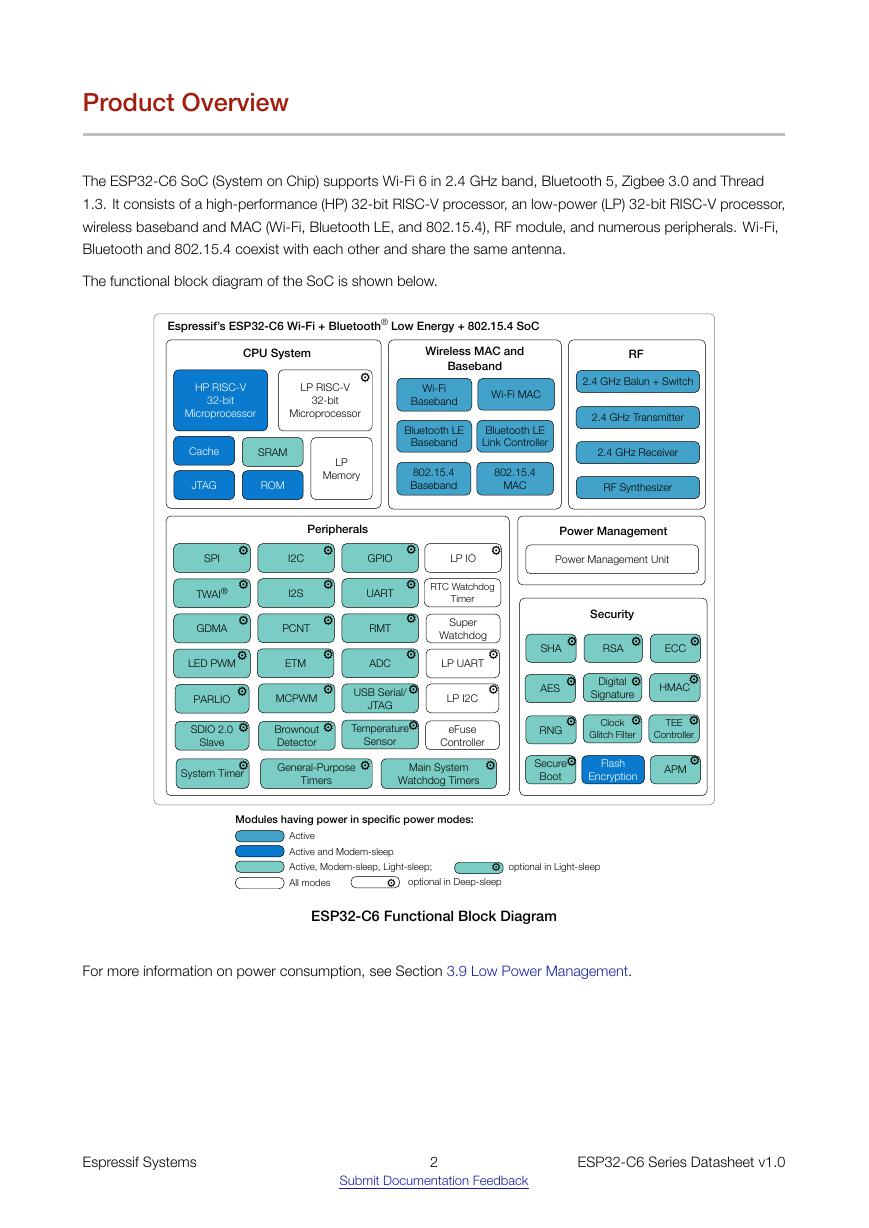
Product Overview The ESP32-C6 SoC (System on Chip) supports Wi-Fi 6 in 2.4 GHz band, Bluetooth 5, Zigbee 3.0 and Thread 1.3. It consists of a high-performance (HP) 32-bit RISC-V processor, an low-power (LP) 32-bit RISC-V processor, wireless baseband and MAC (Wi-Fi, Bluetooth LE, and 802.15.4), RF module, and numerous peripherals. Wi-Fi, Bluetooth and 802.15.4 coexist with each other and share the same antenna. The functional block diagram of the SoC is shown below. ESP32-C6 Functional Block Diagram For more information on power consumption, see Section 3.9 Low Power Management. Espressif Systems 2 ESP32-C6 Series Datasheet v1.0 Submit Documentation Feedback CPU SystemWireless MAC and BasebandWi-Fi MAC Wi-Fi BasebandBluetooth LE Link ControllerBluetooth LE Baseband2.4 GHz Balun + Switch2.4 GHz Receiver2.4 GHz TransmitterRF SynthesizerRFSecurityHP RISC-V32-bitMicroprocessorJTAGCachePeripherals Espressif’s ESP32-C6 Wi-Fi + Bluetooth® Low Energy + 802.15.4 SoCSRAMMCPWMGPIOUARTTWAI®General-Purpose TimersI2SI2CPCNTLED PWMUSB Serial/JTAGSPIRMTADCSystem TimerLP IOTemperature SensorLP MemoryRTC Watchdog TimerPower Management UnitPower ManagementDigital SignatureAESHMAC⚙⚙⚙Modules having power in specific power modes:ActiveActive and Modem-sleepActive, Modem-sleep, Light-sleep;optional in Light-sleep⚙GDMAETM⚙SDIO 2.0 Slave802.15.4Baseband802.15.4MACRSASHA⚙⚙ECC⚙BrownoutDetectorLP UARTLP I2CLP RISC-V32-bitMicroprocessorAll modesROMPARLIOeFuse ControllerMain System Watchdog TimersSuper Watchdog⚙⚙⚙⚙⚙⚙⚙⚙⚙⚙⚙⚙⚙⚙⚙⚙⚙⚙⚙⚙RNGClock Glitch FilterTEEController⚙⚙⚙Flash EncryptionSecure Boot⚙APM⚙⚙optional in Deep-sleep⚙⚙⚙⚙
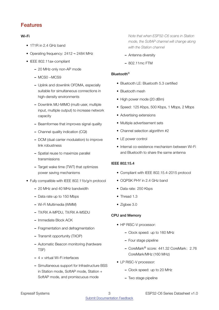
Features Wi-Fi • 1T1R in 2.4 GHz band • Operating frequency: 2412 ~ 2484 MHz • IEEE 802.11ax-compliant – 20 MHz-only non-AP mode – MCS0 ~MCS9 Note that when ESP32-C6 scans in Station mode, the SoftAP channel will change along with the Station channel – Antenna diversity – 802.11mc FTM Bluetooth® – Uplink and downlink OFDMA, especially suitable for simultaneous connections in high-density environments – Downlink MU-MIMO (multi-user, multiple input, multiple output) to increase network capacity • Bluetooth LE: Bluetooth 5.3 certified • Bluetooth mesh • High power mode (20 dBm) • Speed: 125 Kbps, 500 Kbps, 1 Mbps, 2 Mbps • Advertising extensions – Beamformee that improves signal quality • Multiple advertisement sets – Channel quality indication (CQI) • Channel selection algorithm #2 – DCM (dual carrier modulation) to improve • LE power control link robustness – Spatial reuse to maximize parallel transmissions – Target wake time (TWT) that optimizes • Internal co-existence mechanism between Wi-Fi and Bluetooth to share the same antenna IEEE 802.15.4 power saving mechanisms • Compliant with IEEE 802.15.4-2015 protocol • Fully compatible with IEEE 802.11b/g/n protocol • OQPSK PHY in 2.4 GHz band – 20 MHz and 40 MHz bandwidth • Data rate: 250 Kbps – Data rate up to 150 Mbps – Wi-Fi Multimedia (WMM) – TX/RX A-MPDU, TX/RX A-MSDU – Immediate Block ACK – Fragmentation and defragmentation – Transmit opportunity (TXOP) – Automatic Beacon monitoring (hardware TSF) – 4 × virtual Wi-Fi interfaces – Simultaneous support for Infrastructure BSS in Station mode, SoftAP mode, Station + SoftAP mode, and promiscuous mode • Thread 1.3 • Zigbee 3.0 CPU and Memory • HP RISC-V processor: – Clock speed: up to 160 MHz – Four stage pipeline – CoreMark® score: 441.32 CoreMark;2.76 CoreMark/MHz (160 MHz) • LP RISC-V processor: – Clock speed: up to 20 MHz – Two stage pipeline Espressif Systems 3 ESP32-C6 Series Datasheet v1.0 Submit Documentation Feedback
• L1 cache: 32 KB • ROM: 320 KB • HP SRAM: 512 KB • LP SRAM: 16 KB • Timers: – 1 × 52-bit system timer – 2 × 54-bit general-purpose timers – 3 × digital watchdog timers • Supported SPI protocols: SPI, Dual SPI, Quad – 1 × analog watchdog timer SPI, QPI interfaces that allow connection to flash and other SPI devices off the chip’s package Power Management • Flash controller with cache is supported • Flash in-Circuit Programming (ICP) is supported Advanced Peripheral Interfaces • 30 × GPIOs (QFN40), or 22 × GPIOs (QFN32) • Analog interfaces: • Fine-resolution power control through a selection of clock frequency, duty cycle, Wi-Fi operating modes, and individual power control of internal components • Four power modes designed for typical scenarios: Active, Modem-sleep, Light-sleep, Deep-sleep – 1 × 12-bit SAR ADC, up to 7 channels • Power consumption in Deep-sleep mode is 7 µA – 1 × temperature sensor • Digital interfaces: – 2 × UART – 1 × Low-power (LP) UART • Low-power (LP) memory remains powered on in Deep-sleep mode Security • Secure boot - permission control on accessing – 2 × SPI ports for communication with flash internal and external memory – 1 × General purpose SPI port – 1 × I2C – 1 × Low-power (LP) I2C – 1 × I2S – 1 × Pulse count controller – 1 × USB Serial/JTAG controller – 2 × TWAI® controller, compatible with ISO 11898-1 (CAN Specification 2.0) – 1 × SDIO 2.0 slave controller – LED PWM controller, up to 6 channels – 1 × Motor Control PWM (MCPWM) – 1 × Remote control peripheral (TX/RX) – 1 × Parallel IO interface (PARLIO) – General DMA controller, with 3 transmit channels and 3 receive channels • Flash encryption - memory encryption and decryption • 4096-bit OTP, up to 1792 bits for users • Trusted execution environment (TEE) controller and access permission management (APM) • Cryptographic hardware acceleration: – AES-128/256 (FIPS PUB 197) – ECC – HMAC – RSA – SHA – Digital signature – Hash (FIPS PUB 180-4) • External Memory Encryption and Decryption (XTS_AES) – Event task matrix (ETM) • Random Number Generator (RNG) Espressif Systems 4 ESP32-C6 Series Datasheet v1.0 Submit Documentation Feedback
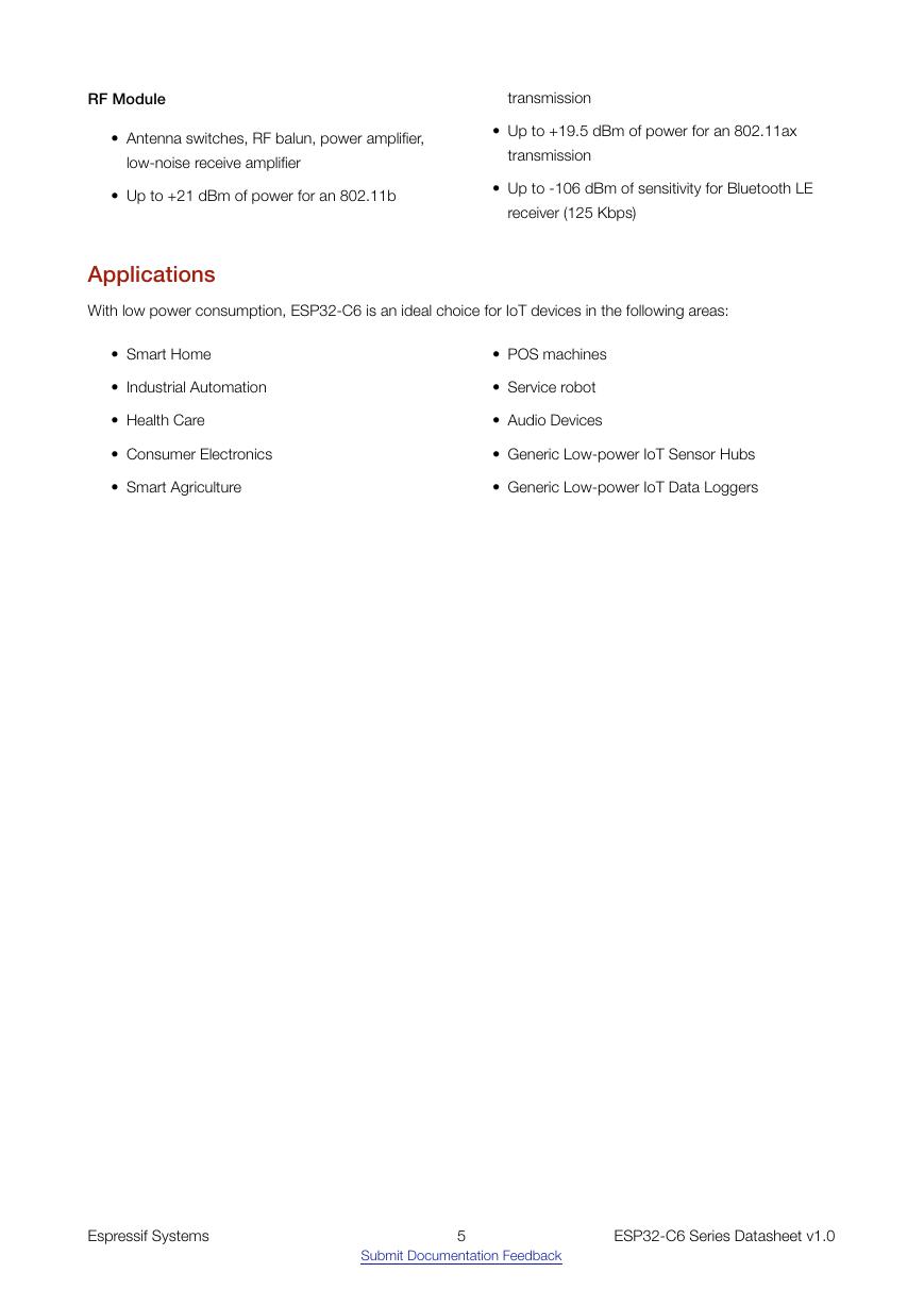
RF Module transmission • Antenna switches, RF balun, power amplifier, low-noise receive amplifier • Up to +21 dBm of power for an 802.11b • Up to +19.5 dBm of power for an 802.11ax transmission • Up to -106 dBm of sensitivity for Bluetooth LE receiver (125 Kbps) Applications With low power consumption, ESP32-C6 is an ideal choice for IoT devices in the following areas: • Smart Home • Industrial Automation • Health Care • Consumer Electronics • Smart Agriculture • POS machines • Service robot • Audio Devices • Generic Low-power IoT Sensor Hubs • Generic Low-power IoT Data Loggers Espressif Systems 5 ESP32-C6 Series Datasheet v1.0 Submit Documentation Feedback
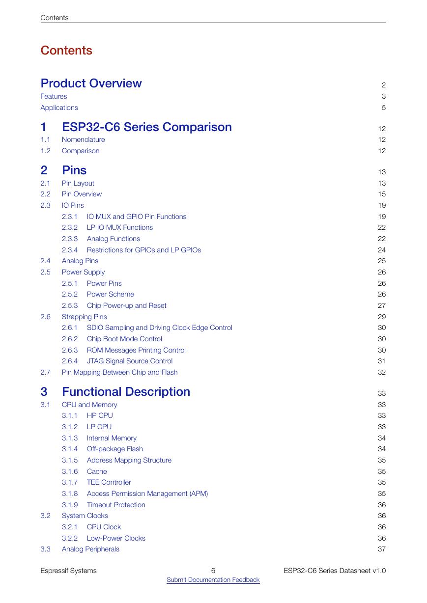
Contents Contents Product Overview Features Applications 1 ESP32-C6 Series Comparison 1.1 1.2 Nomenclature Comparison 2 Pins 2.1 2.2 2.3 IO MUX and GPIO Pin Functions LP IO MUX Functions Analog Functions Pin Layout Pin Overview IO Pins 2.3.1 2.3.2 2.3.3 2.3.4 Restrictions for GPIOs and LP GPIOs Analog Pins Power Supply 2.5.1 2.5.2 2.5.3 Chip Power-up and Reset Strapping Pins 2.6.1 2.6.2 Chip Boot Mode Control 2.6.3 ROM Messages Printing Control 2.6.4 Pin Mapping Between Chip and Flash Power Pins Power Scheme JTAG Signal Source Control 3 Functional Description 3.1 2.4 2.5 2.6 2.7 3.2 3.3 SDIO Sampling and Driving Clock Edge Control CPU and Memory 3.1.1 HP CPU LP CPU 3.1.2 3.1.3 Internal Memory 3.1.4 Off-package Flash 3.1.5 3.1.6 Cache 3.1.7 3.1.8 3.1.9 System Clocks 3.2.1 CPU Clock 3.2.2 Analog Peripherals Low-Power Clocks Address Mapping Structure TEE Controller Access Permission Management (APM) Timeout Protection 2 3 5 12 12 12 13 13 15 19 19 22 22 24 25 26 26 26 27 29 30 30 30 31 32 33 33 33 33 34 34 35 35 35 35 36 36 36 36 37 Espressif Systems 6 ESP32-C6 Series Datasheet v1.0 Submit Documentation Feedback
Analog-to-Digital Converter (ADC) Temperature Sensor Serial Peripheral Interface (SPI) I2C Interface I2S Interface Pulse Count Controller (PCNT) 3.3.1 3.3.2 Digital Peripherals 3.4.1 Universal Asynchronous Receiver Transmitter (UART) 3.4.2 3.4.3 3.4.4 3.4.5 3.4.6 USB Serial/JTAG Controller 3.4.7 3.4.8 3.4.9 3.4.10 Motor Control PWM (MCPWM) 3.4.11 Remote Control Peripheral 3.4.12 Parallel IO (PARLIO) Controller 3.4.13 General DMA Controller (GDMA) 3.4.14 Event Task Matrix (ETM) Radio 3.5.1 3.5.2 3.5.3 Clock Generator TWAI® Controller SDIO 2.0 Slave Controller LED PWM Controller 2.4 GHz Receiver 2.4 GHz Transmitter Contents 3.4 3.5 3.7 3.8 3.6 Wi-Fi 3.6.1 Wi-Fi Radio and Baseband 3.6.2 Wi-Fi MAC 3.6.3 Networking Features Bluetooth LE 3.7.1 Bluetooth LE PHY 3.7.2 Bluetooth LE Link Controller 802.15.4 3.8.1 3.8.2 Low Power Management 802.15.4 PHY 802.15.4 MAC 3.9 3.10 Timers 3.10.1 System Timer 3.10.2 General Purpose Timers 3.10.3 Watchdog Timers 3.11 Cryptography/Security Components 3.11.1 AES Accelerator (AES) 3.11.2 ECC Accelerator (ECC) 3.11.3 HMAC Accelerator (HMAC) 3.11.4 RSA Accelerator (RSA) 3.11.5 SHA Accelerator (SHA) 3.11.6 Digital Signature (DS) 3.11.7 External Memory Encryption and Decryption (XTS_AES) 3.11.8 Random Number Generator (RNG) 3.12 Peripheral Pin Configurations 37 37 37 37 37 38 38 38 39 39 39 40 40 41 41 41 41 42 42 42 42 43 43 43 44 44 45 45 45 45 46 46 46 46 47 47 48 48 48 49 49 49 50 50 51 51 Espressif Systems 7 ESP32-C6 Series Datasheet v1.0 Submit Documentation Feedback
Contents 4 Electrical Characteristics 4.1 4.2 4.3 4.4 4.5 4.6 Absolute Maximum Ratings Recommended Power Supply Characteristics VDD_SPI Output Characteristics DC Characteristics (3.3 V, 25 °C) ADC Characteristics Current Consumption 4.6.1 RF Current Consumption in Active Mode 4.6.2 Current Consumption in Other Modes Reliability 4.7 5 RF Characteristics 5.1 Wi-Fi Radio 5.2 5.3 5.1.1 Wi-Fi RF Transmitter (TX) Characteristics 5.1.2 Wi-Fi RF Receiver (RX) Characteristics Bluetooth LE Radio 5.2.1 Bluetooth LE RF Transmitter (TX) Characteristics 5.2.2 Bluetooth LE RF Receiver (RX) Characteristics 802.15.4 Radio 5.3.1 5.3.2 802.15.4 RF Transmitter (TX) Characteristics 802.15.4 RF Receiver (RX) Characteristics 6 Packaging 7 Related Documentation and Resources Appendix A – ESP32-C6 Consolidated Pin Overview Revision History 54 54 54 55 55 56 56 56 57 58 59 59 59 60 62 62 64 66 66 66 67 68 69 71 Espressif Systems 8 ESP32-C6 Series Datasheet v1.0 Submit Documentation Feedback
分享到:
收藏