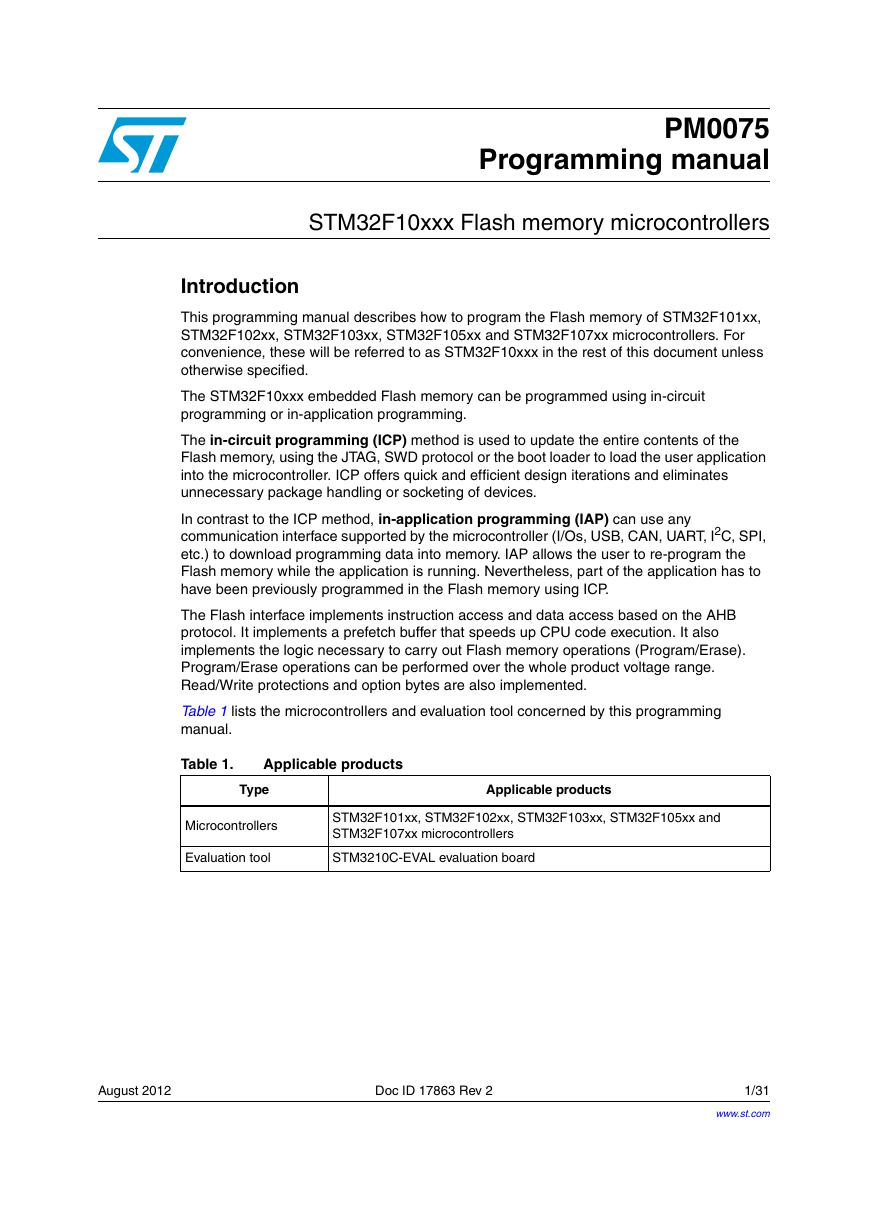
Table 1. Applicable products
1 Overview
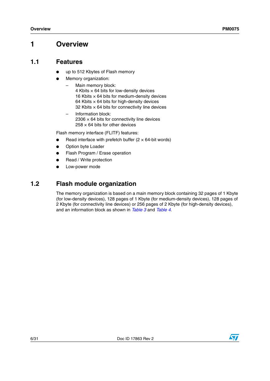
1.1 Features
1.2 Flash module organization
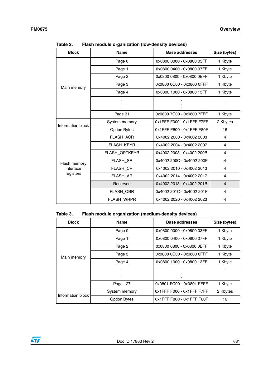
Table 2. Flash module organization (low-density devices)
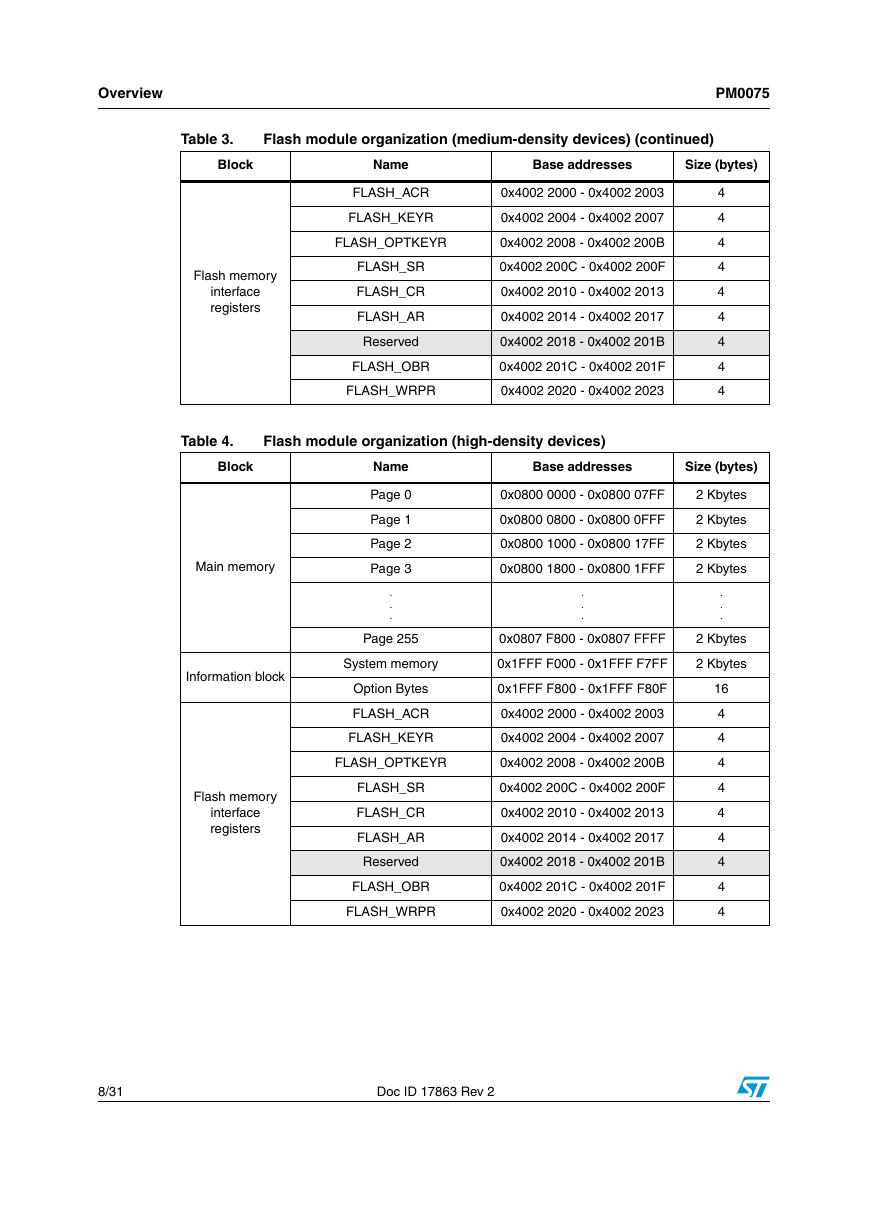
Table 3. Flash module organization (medium-density devices)
Table 4. Flash module organization (high-density devices)
Table 5. Flash module organization (connectivity line devices)
2 Reading/programming the embedded Flash memory
2.1 Introduction
2.2 Read operation
2.2.1 Instruction fetch
2.2.2 D-Code interface
2.2.3 Flash access controller
2.3 Flash program and erase controller (FPEC)
2.3.1 Key values
2.3.2 Unlocking the Flash memory
2.3.3 Main Flash memory programming
Figure 1. Programming procedure
2.3.4 Flash memory erase
Figure 2. Flash memory Page Erase procedure
Figure 3. Flash memory Mass Erase procedure
2.3.5 Option byte programming
2.4 Protections
2.4.1 Read protection
Table 6. Flash memory protection status
2.4.2 Write protection
2.4.3 Option byte block write protection
2.5 Option byte description
Table 7. Option byte format
Table 8. Option byte organization
Table 9. Description of the option bytes
Note: Only bits [16:18] are used, bits [23:19]: 0x1F are not used.
3 Register descriptions
Table 10. Abbreviations
3.1 Flash access control register (FLASH_ACR)
3.2 FPEC key register (FLASH_KEYR)
3.3 Flash OPTKEY register (FLASH_OPTKEYR)
3.4 Flash status register (FLASH_SR)
Note: EOP is asserted at the end of each successful program or erase operation
Note: The STRT bit in the FLASH_CR register should be reset before starting a programming operation.
3.5 Flash control register (FLASH_CR)
3.6 Flash address register (FLASH_AR)
Note: Write access to this register is blocked when the BSY bit in the FLASH_SR register is set.
3.7 Option byte register (FLASH_OBR)
Note: This bit is read-only.
Note: This bit is read-only.
3.8 Write protection register (FLASH_WRPR)
Note: These bits are read-only.
3.9 Flash register map
Table 11. Flash interface - register map and reset values
4 Revision history
Table 12. Document revision history


 V2版本原理图(Capacitive-Fingerprint-Reader-Schematic_V2).pdf
 摄像头工作原理.doc
 VL53L0X简要说明(En.FLVL53L00216).pdf
 原理图(DVK720-Schematic).pdf
 原理图(Pico-Clock-Green-Schdoc).pdf
 原理图(RS485-CAN-HAT-B-schematic).pdf
 File:SIM7500_SIM7600_SIM7800 Series_SSL_Application Note_V2.00.pdf
 ADS1263(Ads1262).pdf
 原理图(Open429Z-D-Schematic).pdf
 用户手册(Capacitive_Fingerprint_Reader_User_Manual_CN).pdf
 CY7C68013A(英文版)(CY7C68013A).pdf
 TechnicalReference_Dem.pdf