PICkit 3 In-Circuit Debugger/Programmer User’s Guide For MPLAB X IDE
EU Declaration of Conformity
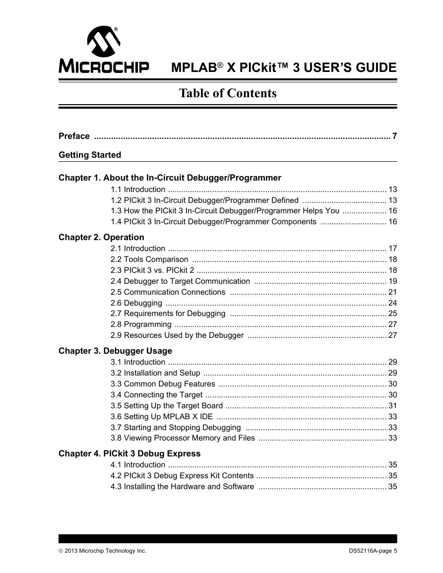
Table of Contents
Preface
INTRODUCTION
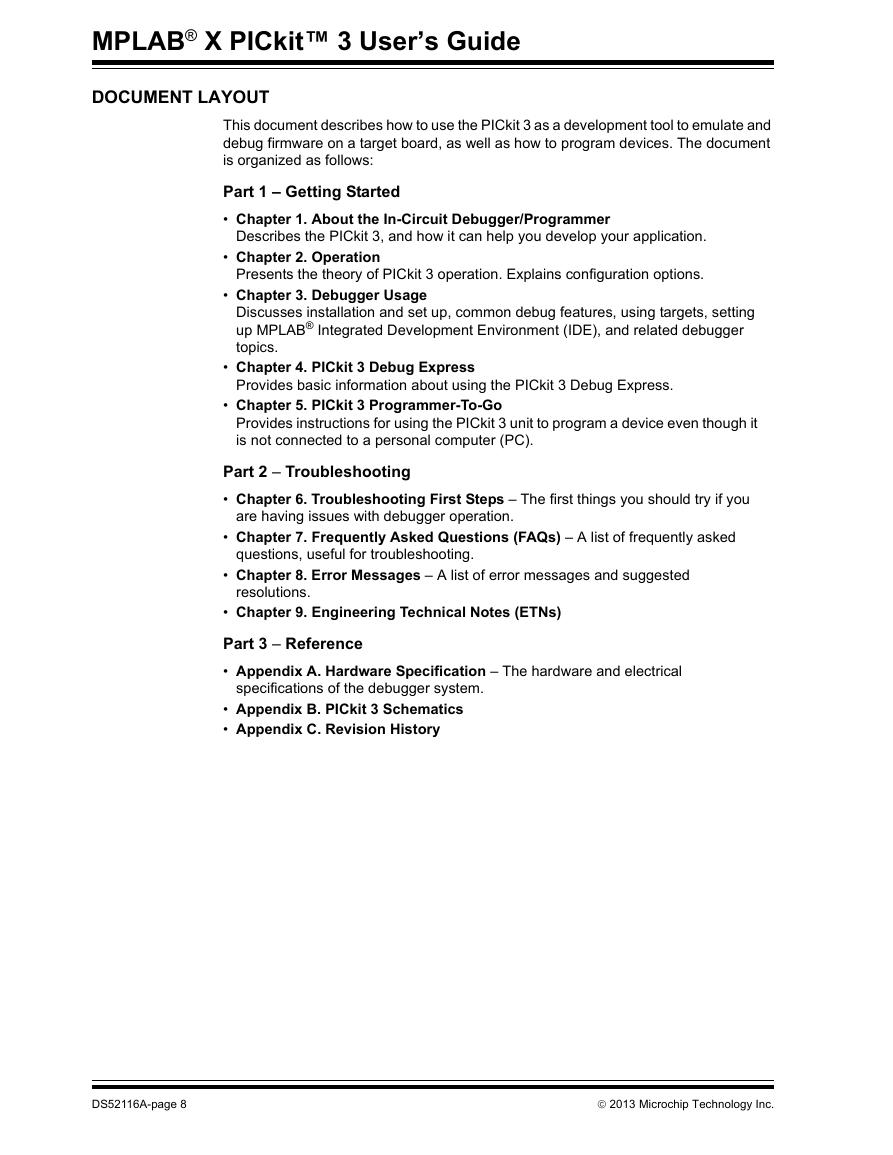
DOCUMENT LAYOUT
CONVENTIONS USED IN THIS GUIDE
DOCUMENTATION CONVENTIONS
RECOMMENDED READING
Part 1 – Getting Started
Chapter 1. About the In-Circuit Debugger/Programmer
1.1 Introduction
1.2 PICkit 3 In-Circuit Debugger/Programmer Defined
Figure 1-1: PICkit™ 3 MCU In-Circuit Debugger/Programmer
1.2.1 Lanyard Loop
1.2.2 USB Port Connection
1.2.3 Pin 1 Marker
1.2.4 Programming Connector
Figure 1-2: PICKIT™ 3 Programmer Connector PinOut
1.2.5 Indicator LEDs
1.2.6 Push Button
1.3 How the PICkit 3 In-Circuit Debugger/Programmer Helps You
1.4 PICkit 3 In-Circuit Debugger/Programmer Components
Figure 1-3: Basic Debugger System
Chapter 2. Operation
2.1 Introduction
2.2 Tools Comparison
Table 2-1: Debug Tools Comparison
2.3 PICkit 3 vs. PICkit 2
2.4 Debugger to Target Communication
Figure 2-1: Standard Debugger System – Device with On-Board ICE Circuitry
Figure 2-2: Standard Debugger System – ICE Device
2.5 Communication Connections
2.5.1.1 Using Single In-Line Connector
Table 2-2: Target Connector Pinout
2.5.1.2 Using An Adapter
Figure 2-3: Standard RJ-11 Connection at Target
Figure 2-4: Standard Connection Target Circuitry
Figure 2-5: Improper Circuit components
2.6 Debugging
Figure 2-6: Proper connections for programming
2.7 Requirements for Debugging
Figure 2-7: PICkit™ 3 Debugger Ready for Debugging
2.8 Programming
2.9 Resources Used by the Debugger
Chapter 3. Debugger Usage
3.1 Introduction
3.2 Installation and Setup
3.3 Common Debug Features
3.4 Connecting the Target
Figure 3-1: Insert Communications and USB/Power Cables
3.5 Setting Up the Target Board
3.5.1 Using Production Devices
3.5.2 Using ICE Devices
Figure 3-2: Using an ICD Header Board
3.5.4 Powering the Target
3.6 Setting Up MPLAB X IDE
3.7 Starting and Stopping Debugging
3.8 Viewing Processor Memory and Files
Chapter 4. PICkit 3 Debug Express
4.1 Introduction
4.2 PICkit 3 Debug Express Kit Contents
4.3 Installing the Hardware and Software
4.3.1 Reserved Resources
Figure 4-1: Connecting the Demo Board to the PICkit™ 3
Chapter 5. PICkit 3 Programmer-To-Go
5.1 Introduction
5.2 USB Power for PICkit 3 Programmer-To-Go
5.2.1 Power Requirements
5.3 PICkit 3 Programmer-To-Go Supported Devices
Table 5-1: Programmer-To-Go Supported Devices
5.4 Setting up PICkit 3 for Programmer-To-Go Operation
5.4.1 Set Up Programmer-to-Go
Figure 5-1: PICkit 3 Project Properties
Figure 5-2: Name the Image
Figure 5-3: Programmer To Go Tab
5.4.2 Download to PICkit 3 Complete
Figure 5-4: Download to PICkit 3
5.5 Using PICkit 3 Programmer-To-Go
Table 5-2: Programmer-To-Go Operation Feedback Codes
5.6 Exiting Programmer-To-Go Mode
Part 2 – Troubleshooting
Chapter 6. Troubleshooting First Steps
6.1 Introduction
6.2 The 5 Questions to Answer First
6.3 Top 10 Reasons Why You Can’t Debug
6.4 Other Things to Consider
Chapter 7. Frequently Asked Questions (FAQs)
7.1 Introduction
7.2 How Does It Work
7.3 What’s Wrong
Chapter 8. Error Messages
8.1 Introduction
8.2 Specific Error Messages
8.3 General Corrective Actions
Chapter 9. Engineering Technical Notes (ETNs)
Part 3 – Reference
Appendix A. Hardware Specification
A.1 Introduction
A.2 Highlights
A.3 Declaration of Conformity
A.4 USB Port/Power
A.5 PICkit 3 In-Circuit Debugger/Programmer
A.6 Standard Communication Hardware
Figure A-1: 6-Pin Standard Pinout
A.6.2.1 Modular Connector Specification
Figure A-2: Modular Connector Pinout of Target Board
A.6.2.2 Modular Plug Specification
A.6.2.3 Modular Cable Specification
A.7 Target Board Considerations
Appendix B. PICkit 3 Schematics
Figure B-1: PICkit™ 3 Schematic Diagram (Page 1 of 2)
Figure B-2: PICkit™ 3 Schematic Diagram (Page 2 of 2)
Appendix C. Revision History
Glossary
Index
Worldwide Sales and Service



 V2版本原理图(Capacitive-Fingerprint-Reader-Schematic_V2).pdf
 摄像头工作原理.doc
 VL53L0X简要说明(En.FLVL53L00216).pdf
 原理图(DVK720-Schematic).pdf
 原理图(Pico-Clock-Green-Schdoc).pdf
 原理图(RS485-CAN-HAT-B-schematic).pdf
 File:SIM7500_SIM7600_SIM7800 Series_SSL_Application Note_V2.00.pdf
 ADS1263(Ads1262).pdf
 原理图(Open429Z-D-Schematic).pdf
 用户手册(Capacitive_Fingerprint_Reader_User_Manual_CN).pdf
 CY7C68013A(英文版)(CY7C68013A).pdf
 TechnicalReference_Dem.pdf