logo资料库

Scanner 900(KODAK IMAGELINK 900 和 923).pdf

第1页 / 共114页
第2页 / 共114页
第3页 / 共114页
第4页 / 共114页
第5页 / 共114页
第6页 / 共114页
第7页 / 共114页
第8页 / 共114页
资料共114页,剩余部分请下载后查看
1 INTRODUCTION
Scanner features
Scanner options
Scanner components
Front view
Rear view
Status display
Operating keys and indicators
2 BASIC CONCEPTS
Modes
Linked modes
Image addresses
Assigning an image address
Image address formats
Indexing schemes
Single level indexing
Two level indexing
Two level offset indexing
Three level indexingThree level indexing
Three level offset indexing
Controlling document level changes
Batching
Special considerations
Checking the meters
Scanning considerations
Image headers
Header flags
3 GETTING STARTED
Turning on the Scanner
Selecting the language display
Calibrating the Scanner
Unsuccessful calibration
Adjusting the feed and separator roller gap
Adjusting the feed shelf position
Adjusting the feed shelf side guides
Adjusting the exit hopper side guides and end stop
Changing the deflector
Preparing documents for scanning
4 OPERATING THE SCANNER
Overview
Selecting a mode
Temporary operating values
Feeding documents
Feeding thick documents
5 FUNCTION CODES
Using function codes
Function code summary
Function code descriptions
6 OPERATOR MESSAGES
Users
System administrators
Operator message listing
7 TROUBLESHOOTING
Trouble and remedy chart
Clearing the document path
The document path
Clearing documents
8 SCANNER MAINTENANCE
Cleaning tasks
Cleaning materials
Daily maintenance procedures
Cleaning the imaging guides
Cleaning the document scanning array
Weekly maintenance procedures
Vacuuming inside the Scanner
Cleaning the feed and separator rollers
Cleaning the cabinet
Monthly maintenance procedures
Checking the air filter
Replacement procedures
Replacing the air filter
Replacing the document scanning array lamp
Replacing the exposure lamps
User’s Manual A-41069 Part No. 636914 January 1993 KODAK IMAGEL I N K Scanner 900 and 923 MBUSDINESS IMR AGING SS YSTEMS
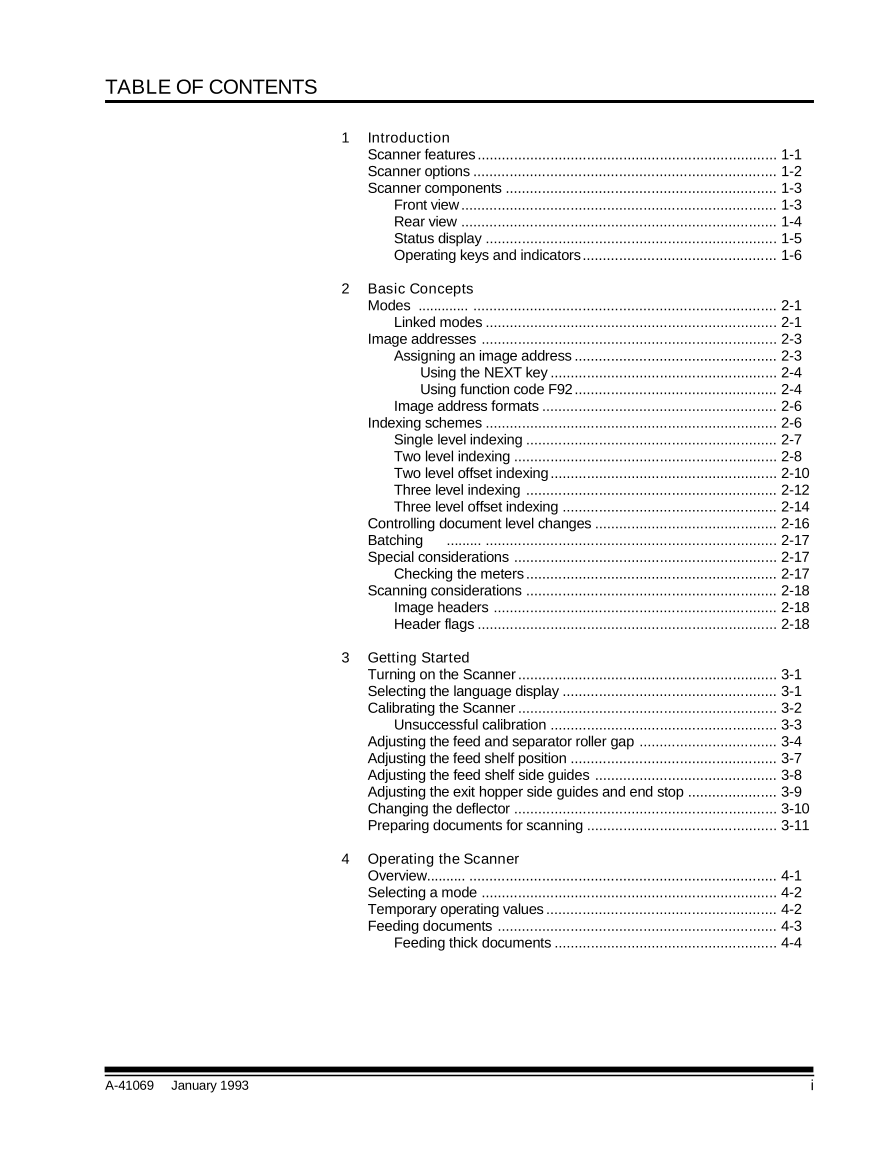
TABLE OF CONTENTS 1 Introduction Scanner features .......................................................................... 1-1 Scanner options ........................................................................... 1-2 Scanner components ................................................................... 1-3 Front view.............................................................................. 1-3 Rear view .............................................................................. 1-4 Status display ........................................................................ 1-5 Operating keys and indicators................................................ 1-6 2 Basic Concepts Modes ............. ........................................................................... 2-1 Linked modes ........................................................................ 2-1 Image addresses ......................................................................... 2-3 Assigning an image address .................................................. 2-3 Using the NEXT key ........................................................ 2-4 Using function code F92.................................................. 2-4 Image address formats .......................................................... 2-6 Indexing schemes ........................................................................ 2-6 Single level indexing .............................................................. 2-7 Two level indexing ................................................................. 2-8 Two level offset indexing ........................................................ 2-10 Three level indexing .............................................................. 2-12 Three level offset indexing ..................................................... 2-14 Controlling document level changes ............................................. 2-16 Batching ......... ........................................................................ 2-17 Special considerations ................................................................. 2-17 Checking the meters .............................................................. 2-17 Scanning considerations .............................................................. 2-18 Image headers ...................................................................... 2-18 Header flags .......................................................................... 2-18 3 Getting Started Turning on the Scanner ................................................................ 3-1 Selecting the language display ..................................................... 3-1 Calibrating the Scanner ................................................................ 3-2 Unsuccessful calibration ........................................................ 3-3 Adjusting the feed and separator roller gap .................................. 3-4 Adjusting the feed shelf position ................................................... 3-7 Adjusting the feed shelf side guides ............................................. 3-8 Adjusting the exit hopper side guides and end stop ...................... 3-9 Changing the deflector ................................................................. 3-10 Preparing documents for scanning ............................................... 3-11 4 Operating the Scanner Overview.......... ............................................................................ 4-1 Selecting a mode ......................................................................... 4-2 Temporary operating values ......................................................... 4-2 Feeding documents ..................................................................... 4-3 Feeding thick documents ....................................................... 4-4 A-41069 January 1993 i
5 Operator Functions Using function codes .................................................................... 5-1 Function code summary ............................................................... 5-2 Function code descriptions ........................................................... 5-4 6 Operator Messages Required actions .......................................................................... 6-1 User....... ................................................................................ 6-1 System administrator ............................................................. 6-1 Operator message listing ............................................................. 6-2 7 Troubleshooting Trouble and remedy chart ............................................................ 7-1 Clearing the document path ......................................................... 7-3 The document path ................................................................ 7-4 Clearing documents ............................................................... 7-4 Area A - The feeder/horizontal transport area .................. 7-5 Area B - The imaging guide area ..................................... 7-6 Area C - The lower roller assembly area .......................... 7-7 Area D - The vertical transport area ................................. 7-8 Area E - The upper turn area ........................................... 7-9 Area F - The document exit area ..................................... 7-10 8 Scanner 900 Maintenance Cleaning tasks ............................................................................. 8-1 Cleaning materials ....................................................................... 8-1 Daily maintenance procedures ..................................................... 8-2 Cleaning the imaging guides .................................................. 8-2 Weekly maintenance procedures ................................................. 8-4 Vacuuming inside the Scanner .............................................. 8-4 Cleaning the cabinet .............................................................. 8-6 Cleaning the feed and separator rollers.................................. 8-7 Monthly maintenance procedures................................................. 8-8 Checking the air filter ............................................................. 8-8 Replacement procedures ............................................................. 8-9 Replacing the air filter ............................................................ 8-9 Replacing the exposure lamps ............................................... 8-10 9 Scanner 923 Maintenance Cleaning tasks ............................................................................. 9-1 Cleaning materials ....................................................................... 9-1 Daily maintenance procedures ..................................................... 9-2 Cleaning the imaging guides .................................................. 9-2 Cleaning the document scanning array .................................. 9-4 Weekly maintenance procedures ................................................. 9-6 Vacuuming inside the Scanner .............................................. 9-6 Cleaning the feed and separator rollers.................................. 9-9 Cleaning the cabinet .............................................................. 9-10 Monthly maintenance procedures................................................. 9-11 Checking the air filter ............................................................. 9-11 Replacement procedures ............................................................. 9-12 Replacing the air filter ............................................................ 9-12 Replacing the document scanning array lamp ........................ 9-13 Replacing the exposure lamps ............................................... 9-16 ii A-41069 January 1993
1 INTRODUCTION The KODAK IMAGELINK™ Scanner 900 is a medium- to high-speed (up to 120 pages per minute†), high-resolution (up to 400 dpi) rotary scanner designed for medium- to high-volume digitial capture of business documents. The Scanner 900 captures printed characters, handwritten text, and graphics from documents of various sizes (from 2.5 in [64 mm] to 20 in [508 mm] long and from 2.5 in [64 mm] to 12 in [305 mm] wide) and thicknesses (standard documents up to 0.014 in [0.36 mm]; even thicker documents may be scanned using the gap release feature). The KODAK IMAGELINK™ Scanner 923 is a high-speed (up to 144 pages per minute†), medium- to high-resolution (up to 300 dpi) rotary scanner designed for high-volume digitial capture of business documents. The Scanner 923 captures printed characters, handwritten text, and graphics from documents of various sizes (from 2.5 in [64 mm] to 20 in [508 mm] long and from 2.5 in [64 mm] to 12 in [305 mm] wide) and thicknesses (standard documents up to 0.014 inches [0.36 mm]; even thicker documents may be scanned using the gap release feature). Scanner features The following features make the Scanners unique: • Easy-to-reach Control Panel keys, identified by graphic symbols. • A high-speed document transport system. • A two-line 80-character display for status information and operator messages. • Full programmability of all eighteen (18) application modes, with override capability. • Linked modes may be used to carry over the Image Address from one mode to another. • Programmable keys to perform commonly-used functions. • Transport-on functions; allows twenty-seven of the function codes to be executed while the transport is running. • Audible tones for selected functions, such as footswitch, patch reading, etc. • English or other language message display. • A large, built-in workshelf. • An adaptible, modular design for easy addition of accessories. † Standard-sized documents fed in landscape orientation; continuous transport using the Semi-Automatic Feeder. A-41069 January 1993 1 - 1
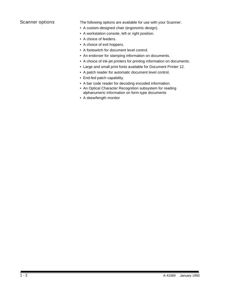
Scanner options The following options are available for use with your Scanner: • A custom-designed chair (ergonomic design). • A workstation console, left or right position. • A choice of feeders. • A choice of exit hoppers. • A footswitch for document level control. • An endorser for stamping information on documents. • A choice of ink-jet printers for printing information on documents. • Large and small print fonts available for Document Printer 12. • A patch reader for automatic document level control. • End-fed patch capability. • A bar code reader for decoding encoded information. • An Optical Character Recognition subsystem for reading alphanumeric information on form-type documents • A skew/length monitor 1 - 2 A-41069 January 1993
Scanner components The following illustrations and descriptions will assist you in locating and becoming familiar with the Scanner components: Front view Control Panel – contains the Status Display, Indicators, and Operating Keys used to control the Scanner. Exit Hopper – accepts documents after they have been scanned. Feed and Separator Rollers – provide smooth feeding of documents of various sizes and textures. Feed Tray – holds documents prior to feeding. Gap Adjustment Knob – allows you to manually adjust the space between the feed and separator rollers for documents of varying thicknesses. Gap Release Lever – allows you to open the feed gap for thicker documents to be fed into the transport. Left-Side Access Door – provides access to select components. Right-Side Access Door – provides access to the transport system components. Side Panel Switch – allows you to turn the transport system on/off. Top Cover – provides access behind the transport area. A-41069 January 1993 1 - 3
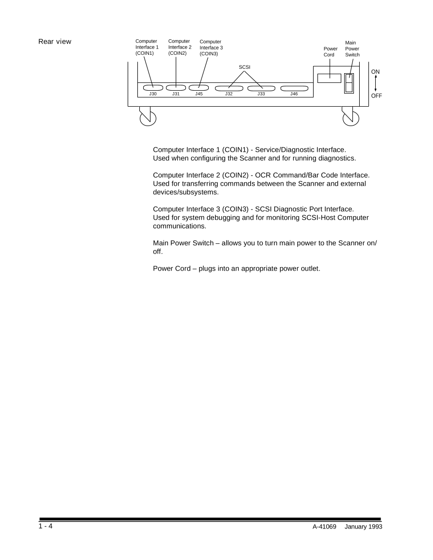
Rear view Computer Computer Computer Main Interface 1 Interface 2 Interface 3 Power Power (COIN1) (COIN2) (COIN3) Cord Switch SCSI ON J30 J31 J45 J32 J33 J46 OFF Computer Interface 1 (COIN1) - Service/Diagnostic Interface. Used when configuring the Scanner and for running diagnostics. Computer Interface 2 (COIN2) - OCR Command/Bar Code Interface. Used for transferring commands between the Scanner and external devices/subsystems. Computer Interface 3 (COIN3) - SCSI Diagnostic Port Interface. Used for system debugging and for monitoring SCSI-Host Computer communications. Main Power Switch – allows you to turn main power to the Scanner on/ off. Power Cord – plugs into an appropriate power outlet. 1 - 4 A-41069 January 1993
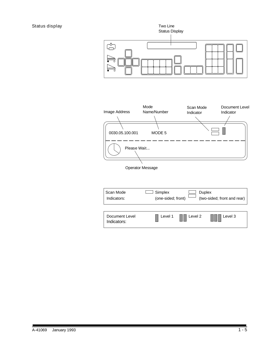
Status display Two Line Status Display Mode Scan Mode Document Level Image Address Name/Number Indicator Indicator 0030.05.100.001 MODE 5 Please Wait... Operator Message Scan Mode Simplex Duplex Indicators: (one-sided; front) (two-sided; front and rear) Document Level Level 1 Level 2 Level 3 Indicators: A-41069 January 1993 1 - 5
分享到:
收藏