Wuxi I-CORE Electronics Co., Ltd.
733-11-I Number:AIP31068L-AX-BJ-153EN
AIP31068L
16COM / 40SEG DRIVER & CONTROLLER FOR DOT MATRIX LCD
Product Specification
Specification Revision History :
Data
2012-03
Version
2012-03-A1
Description
New-made
Address:2F Building9,100Di cui Road, LiYuan Development Zone, Wuxi, jiangsu, China
http://www.i-core. cn
P.C:214072
1/ 28
VER:2012-03-A1
�
Wuxi I-CORE Electronics Co., Ltd.
733-11-I Number:AIP31068L-AX-BJ-153EN
1、GENERAL DESCRIPTION
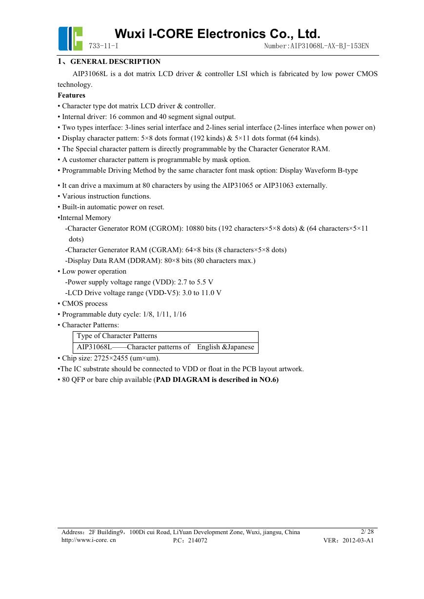
AIP31068L is a dot matrix LCD driver & controller LSI which is fabricated by low power CMOS
technology.
Features
• Character type dot matrix LCD driver & controller.
• Internal driver: 16 common and 40 segment signal output.
• Two types interface: 3-lines serial interface and 2-lines serial interface (2-lines interface when power on)
• Display character pattern: 5×8 dots format (192 kinds) & 5×11 dots format (64 kinds).
• The Special character pattern is directly programmable by the Character Generator RAM.
• A customer character pattern is programmable by mask option.
• Programmable Driving Method by the same character font mask option: Display Waveform B-type
• It can drive a maximum at 80 characters by using the AIP31065 or AIP31063 externally.
• Various instruction functions.
• Built-in automatic power on reset.
•Internal Memory
-Character Generator ROM (CGROM): 10880 bits (192 characters×5×8 dots) & (64 characters×5×11
dots)
-Character Generator RAM (CGRAM): 64×8 bits (8 characters×5×8 dots)
-Display Data RAM (DDRAM): 80×8 bits (80 characters max.)
• Low power operation
-Power supply voltage range (VDD): 2.7 to 5.5 V
-LCD Drive voltage range (VDD-V5): 3.0 to 11.0 V
• CMOS process
• Programmable duty cycle: 1/8, 1/11, 1/16
• Character Patterns:
Type of Character Patterns
AIP31068L——Character patterns of English &Japanese
• Chip size: 2725×2455 (um×um).
•The IC substrate should be connected to VDD or float in the PCB layout artwork.
• 80 QFP or bare chip available (PAD DIAGRAM is described in NO.6)
Address:2F Building9,100Di cui Road, LiYuan Development Zone, Wuxi, jiangsu, China
http://www.i-core. cn
P.C:214072
2/ 28
VER:2012-03-A1
�
Wuxi I-CORE Electronics Co., Ltd.
733-11-I Number:AIP31068L-AX-BJ-153EN
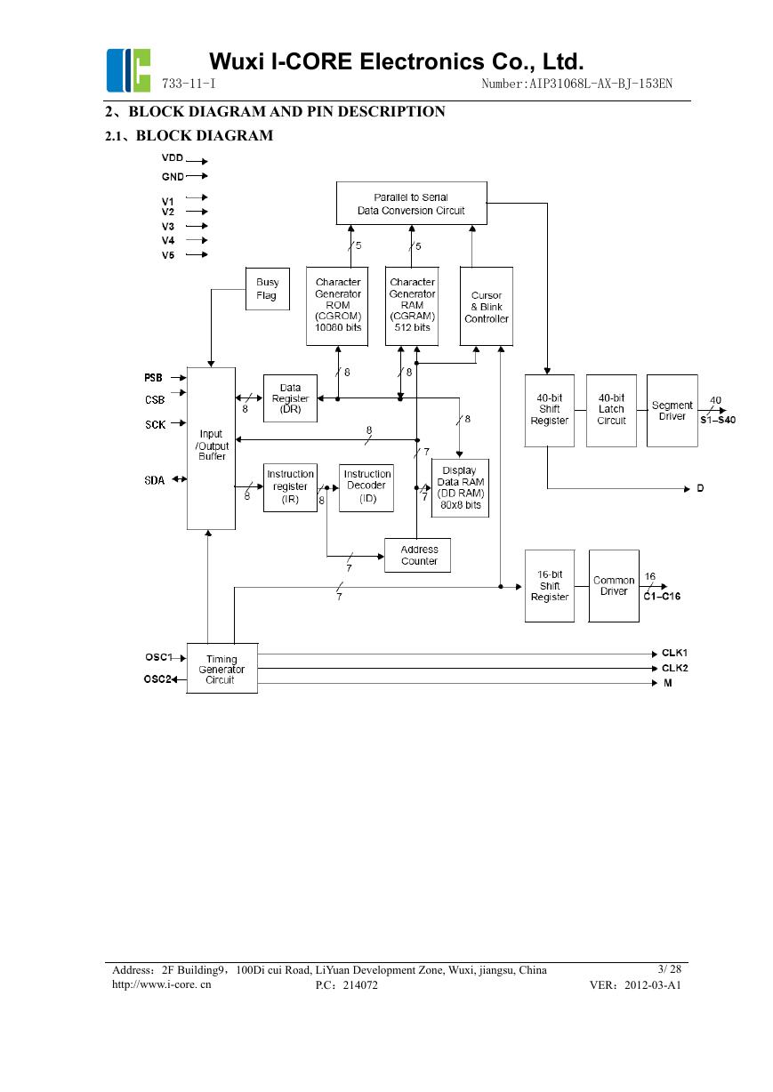
2、BLOCK DIAGRAM AND PIN DESCRIPTION
2.1、BLOCK DIAGRAM
Address:2F Building9,100Di cui Road, LiYuan Development Zone, Wuxi, jiangsu, China
http://www.i-core. cn
P.C:214072
3/ 28
VER:2012-03-A1
�
Wuxi I-CORE Electronics Co., Ltd.
733-11-I Number:AIP31068L-AX-BJ-153EN
2.2、PIN CONFIGURATIONS
2.3、PIN DESCRIPTION
Pin No.
33
23
26~30
1~22
63~80
47~62
Pin Name
I/O
Description
Interface
VDD
GND
V1~V5
Supply Voltage
P
10%,+5V
Supply Voltage for logical circuit
(+3V
Ground (0V)
Bias voltage level for LCD driving
10%)
S1~S40
Segment output
O
Segment signal output for LCD drive
C1~C16
Common output
O Common signal output for LCD drive
Power
Supply
LCD
LCD
Address:2F Building9,100Di cui Road, LiYuan Development Zone, Wuxi, jiangsu, China
http://www.i-core. cn
P.C:214072
4/ 28
VER:2012-03-A1
�
Wuxi I-CORE Electronics Co., Ltd.
733-11-I Number:AIP31068L-AX-BJ-153EN
I
O
Oscillator. When using internal
oscillator, connect external Rf resistor.
If external clock is used, connect it to
OSC1.
Extension driver latch clock
External
resistor/osci
llator
(OSC1)
Extension driver shift clock
O
Outputs the alternating signal to convert
LCD driver waveform to AC.
Extension
driver
Outputs extension driver data
(the 41st dot's data)
Chip select input pins.
When use 3-line interface, CSB pin is
used. When use 2-line interface, CSB pin
is unused, it is floating.
Mode select input pin with pull-high
resistor.
When PSB=”High”, 2-line interface is
selected.
When PSB=”Low”, 3-line interface is
selected.
It will be selected 2-line interface when
power on.
Serial clock input
I/O Serial input data
I
MPU
24
25
31
32
34
35
38
OSC1
OSC2
CLK1
CLK2
M
D
Oscillator
Extension driver
Latch clock
Extension driver
Shift clock
Alternated signal
for LCD driver
output
Display data
interface
CSB
Chip select
39
PSB
Mode select
45
46
36、37
40~44
SCK
SDA
NC
Serial clock input
Serial input data
Not Connect
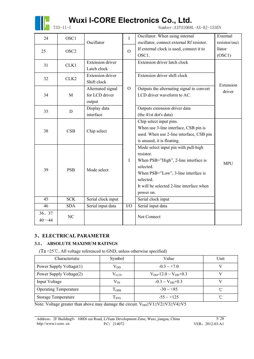
3、ELECTRICAL PARAMETER
3.1、 ABSOLUTE MAXIMUM RATINGS
(Ta =25℃, All voltage referenced to GND, unless otherwise specified)
Characteristic
Symbol
Value
-0.3 ~ +7.0
Power Supply Voltage(1)
Power Supply Voltage(2)
Input Voltage
Operating Temperature
Storage Temperature
Note: Voltage greater than above may damage the circuit. VDD≥V1≥V2≥V3≥V4≥V5
VDD
VLCD
VIN
TOPR
TSTG
-30 ~ +85
-55 ~ +125
VDD-12.0 ~ VDD+0.3
-0.3 ~ VDD+0.3
Address:2F Building9,100Di cui Road, LiYuan Development Zone, Wuxi, jiangsu, China
http://www.i-core. cn
P.C:214072
Unit
V
V
V
℃
℃
5/ 28
VER:2012-03-A1
�
Wuxi I-CORE Electronics Co., Ltd.
733-11-I Number:AIP31068L-AX-BJ-153EN
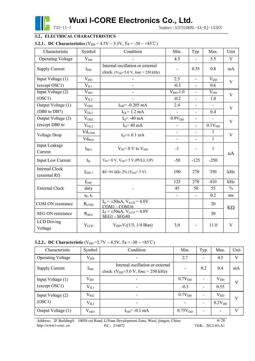
3.2、ELECTRICAL CHARACTERISTICS
3.2.1、DC Characteristics (VDD = 4.5V ~ 5.5V, Ta = -30 ~ +85℃)
Characteristic
Symbol
Condition
-
Internal oscillation or external
clock. (VDD=5.0 V, fosc = 250 kHz)
Min.
4.5
Typ. Max.
5.5
-
-
0.55
0.8
Unit
V
mA
VDD
IDD
VIH1
VIL1
VIH2
VIL2
VOH1
VOL1 I
VOH2
VOL2
VdCOM
VdSEG
IIKG V
Operating Voltage
Supply Current
Input Voltage (1)
(except OSC1)
Input Voltage (2)
(OSC1)
Output Voltage (1)
(DB0 to DB7)
Output Voltage (2)
(except DB0 to
Voltage Drop
Input Leakage
Current
Input Low Current
Internal Clock
(external Rf)
External Clock
COM ON resistance
SEG ON resistance
LCD Driving
Voltage
-
-
-
-
IOH= -0.205 mA
OL= 1.2 mA
IO= -40 mA
IO= 40 mA
IO=± 0.1 mA
IN= 0 V to VDD
2.5
-0.3
VDD-1.0
-0.2
2.4
-
0.9VDD
-
-
-
-1
-
-
-
-
-
-
-
-
-
-
-
VDD
0.6
VDD
1.0
-
0.4
-
0.1VDD
1
1
1
IIL
VIN= 0 V, VDD= 5 V (PULL UP)
-50
-125
-250
fOSC1
fOSC
duty
tR, tF
RCOM
RSEG
VLCD
Rf =91 kΩ± 2% (VDD= 5 V)
-
IO = ±50uA, VLCD = 4.0V
COM1 - COM16
IO = ±50uA, VLCD = 4.0V
SEG1 - SEG40
VDD-V5(1/5, 1/4 Bias)
190
125
45
-
3.0
270
270
50
-
-
350
410
55
0.2
20
30
11.0
V
V
V
V
V
V
uA
kHz
kHz
%
ms
KΩ
3.2.2、DC Characteristic (VDD =2.7V ~ 4.5V, Ta = -30 ~ +85℃)
Characteristic
Operating Voltage
Supply Current
Input Voltage (1)
(except OSC1)
Input Voltage (2)
(OSC1)
Output Voltage (1)
Symbol
VDD
IDD
VIH1
VIL1
VIH2
VIL2
VOH1
Condition
-
Min.
2.7
Typ. Max. Unit
V
4.5
-
Internal oscillation or external
clock. (VDD=3.0 V, fosc = 250 kHz)
-
-
-
-
IOH= -0.1 mA
-
0.2
0.4 mA
0.7VDD
-0.3
0.7VDD
-
0.75VDD
-
-
-
-
-
VDD
0.55
VDD
0.2VDD
-
V
V
V
Address:2F Building9,100Di cui Road, LiYuan Development Zone, Wuxi, jiangsu, China
http://www.i-core. cn
P.C:214072
6/ 28
VER:2012-03-A1
�
Wuxi I-CORE Electronics Co., Ltd.
733-11-I Number:AIP31068L-AX-BJ-153EN
(DB0 to DB7)
Output Voltage (2)
(except DB0 to DB7)
Input Leakage Current
VOL1
VOH2
VOL2
IIKG
IOL= 0.1 mA
IO= -40 mA
IO= 40 mA
VIN= 0 V to VDD
-
0.8VDD
-
-1
-
-
-
-
0.2VDD
-
0.2VDD
1
Input Low Current
IIL
VIN= 0 V, VDD= 3 V (PULL UP)
-10
-50
-120
Internal Clock
(external Rf)
External Clock
COM ON resistance
SEG ON resistance
LCD Driving Voltage
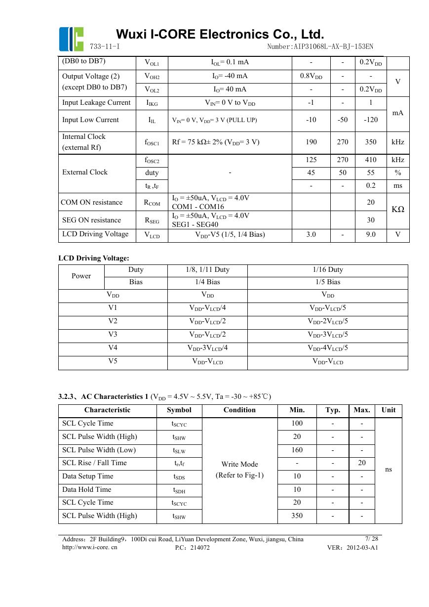
LCD Driving Voltage:
fOSC1 Rf = 75 kΩ± 2% (VDD= 3 V)
fOSC2
duty
tR ,tF
RCOM
RSEG
VLCD
-
IO = ±50uA, VLCD = 4.0V
COM1 - COM16
IO = ±50uA, VLCD = 4.0V
SEG1 - SEG40
VDD-V5 (1/5, 1/4 Bias)
190
125
45
-
3.0
270
350
270
50
-
-
410
55
0.2
20
30
9.0
V
mA
kHz
kHz
%
ms
KΩ
V
Power
Duty
Bias
VDD V
V1
V2
V3
V4
V5
1/8, 1/11 Duty
1/4 Bias
DD
VDD-VLCD/4
VDD-VLCD/2
VDD-VLCD/2
VDD-3VLCD/4
VDD-VLCD V
1/16 Duty
1/5 Bias
VDD
VDD-VLCD/5
VDD-2VLCD/5
VDD-3VLCD/5
VDD-4VLCD/5
DD-VLCD
3.2.3、AC Characteristics 1 (VDD = 4.5V ~ 5.5V, Ta = -30 ~ +85℃)
Characteristic
SCL Cycle Time
SCL Pulse Width (High)
SCL Pulse Width (Low)
SCL Rise / Fall Time
Data Setup Time
Data Hold Time
SCL Cycle Time
SCL Pulse Width (High)
Symbol
tSCYC
tSHW
tSLW
tr,tf
tSDS
tSDH
tSCYC
tSHW
Condition
Write Mode
(Refer to Fig-1)
Min.
100
20
160
-
10
10
20
350
Address:2F Building9,100Di cui Road, LiYuan Development Zone, Wuxi, jiangsu, China
http://www.i-core. cn
P.C:214072
Typ. Max. Unit
ns
-
-
-
-
-
-
-
-
-
-
-
20
-
-
-
-
7/ 28
VER:2012-03-A1
�
Wuxi I-CORE Electronics Co., Ltd.
733-11-I Number:AIP31068L-AX-BJ-153EN
SCL Frequency
SCL Pulse Width (High)
SCL Pulse Width (Low)
Data Setup Time
Data Hold Time
SCL/SDA Rise / Fall Time
START Setup Time
START Hold Time
STOPSetup Time
STOP-START Time
fSCLK
tSHW
tSLW
tSU:DAT
tHD:DAT
tr,tf
tSU:STA
tHD:STA
tSU:STO
tBUF
Read Mode
(Refer to Fig-2)
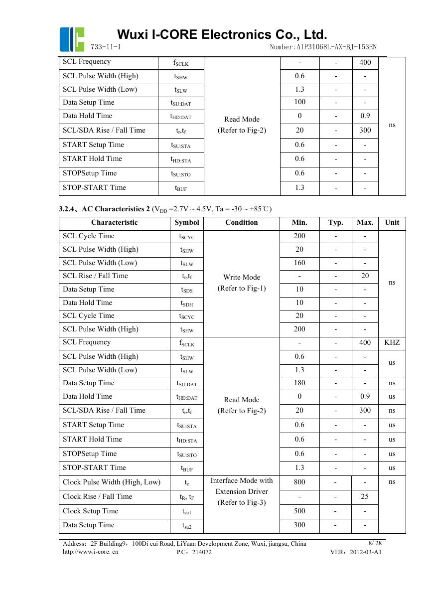
3.2.4、AC Characteristics 2 (VDD =2.7V ~ 4.5V, Ta = -30 ~ +85℃)
Characteristic
SCL Cycle Time
SCL Pulse Width (High)
SCL Pulse Width (Low)
SCL Rise / Fall Time
Data Setup Time
Data Hold Time
SCL Cycle Time
SCL Pulse Width (High)
SCL Frequency
SCL Pulse Width (High)
SCL Pulse Width (Low)
Data Setup Time
Data Hold Time
SCL/SDA Rise / Fall Time
START Setup Time
START Hold Time
STOPSetup Time
STOP-START Time
Clock Pulse Width (High, Low)
Clock Rise / Fall Time
Clock Setup Time
Data Setup Time
Symbol
tSCYC
tSHW
tSLW
tr,tf
tSDS
tSDH
tSCYC
tSHW
fSCLK
tSHW
tSLW
tSU:DAT
tHD:DAT
tr,tf
tSU:STA
tHD:STA
tSU:STO
tBUF
tc
tR, tF
tsu1
tsu2
Condition
Write Mode
(Refer to Fig-1)
Read Mode
(Refer to Fig-2)
Interface Mode with
Extension Driver
(Refer to Fig-3)
-
0.6
1.3
100
0
20
0.6
0.6
0.6
1.3
Min.
200
20
160
-
10
10
20
200
-
0.6
1.3
180
0
20
0.6
0.6
0.6
1.3
800
-
500
300
Address:2F Building9,100Di cui Road, LiYuan Development Zone, Wuxi, jiangsu, China
http://www.i-core. cn
P.C:214072
-
-
-
-
-
-
-
-
-
-
400
-
-
-
0.9
300
-
-
-
-
ns
Typ. Max. Unit
-
-
-
-
-
-
-
-
-
-
-
-
-
-
-
-
-
-
-
-
-
-
-
-
-
20
-
-
-
-
400
-
-
-
0.9
300
-
-
-
-
-
25
-
-
ns
KHZ
us
ns
us
ns
us
us
us
us
ns
8/ 28
VER:2012-03-A1
�



 V2版本原理图(Capacitive-Fingerprint-Reader-Schematic_V2).pdf
 摄像头工作原理.doc
 VL53L0X简要说明(En.FLVL53L00216).pdf
 原理图(DVK720-Schematic).pdf
 原理图(Pico-Clock-Green-Schdoc).pdf
 原理图(RS485-CAN-HAT-B-schematic).pdf
 File:SIM7500_SIM7600_SIM7800 Series_SSL_Application Note_V2.00.pdf
 ADS1263(Ads1262).pdf
 原理图(Open429Z-D-Schematic).pdf
 用户手册(Capacitive_Fingerprint_Reader_User_Manual_CN).pdf
 CY7C68013A(英文版)(CY7C68013A).pdf
 TechnicalReference_Dem.pdf