深 圳 市 微 雪 电 子 有 限 公 司
---------------------------------------------------------------------------------------------------------------------------------------------------------
WAVESHARE ELECTRONICS CO.,LTD
LCD1602 I2C Module
LCD MODULE USER MANUAL
1. FUNCTIONS & FEATURES
Features
一 Characters: 16×2 Lines
一 LCD Mode: STN, Yellow –Green/Blue/Grayish;
一 LCD Controller IC: AiP31068L or Equivalent
一 Driving Method: 1/16 Duty; 1/5Bias
一 Viewing Angie: 6 O’clock direction
一 I2C MPU Interface
一 Backlight: White LED
一 Operating Temperature Range: -20 to +70℃;
一 Storage Temperature Range : -30 to +80℃;
2. MECHANICAL SPECIFICATIONS
SPECIFICATIONS
ITEM
Module Size
View Area
Number of Character
Character Size
Character Pitch
87.0L×32.0W×13.0(max)H
64.5×16.0
16×2 Lines
2.96×5.56
3.55×5.96
3. EXTERNAL DIMENSIONS
UNIT
mm
mm
—
mm
mm
1
�
深 圳 市 微 雪 电 子 有 限 公 司
---------------------------------------------------------------------------------------------------------------------------------------------------------
WAVESHARE ELECTRONICS CO.,LTD
4. BLOCK DIAGRAM
5. POWER SUPPLY
6. PIN DESCRIPTION
ITEM SYMBOL
LEVEL
FUNCTION
2
�
深 圳 市 微 雪 电 子 有 限 公 司
---------------------------------------------------------------------------------------------------------------------------------------------------------
WAVESHARE ELECTRONICS CO.,LTD
1
2
3
4
SDA
SCL
GND
VCC
H/L
H/L
0V
+3.3~5.0V
I2C-Bus Serial Data
I2C-Bus Serial Clock
Power Ground
Power Supply For Logic
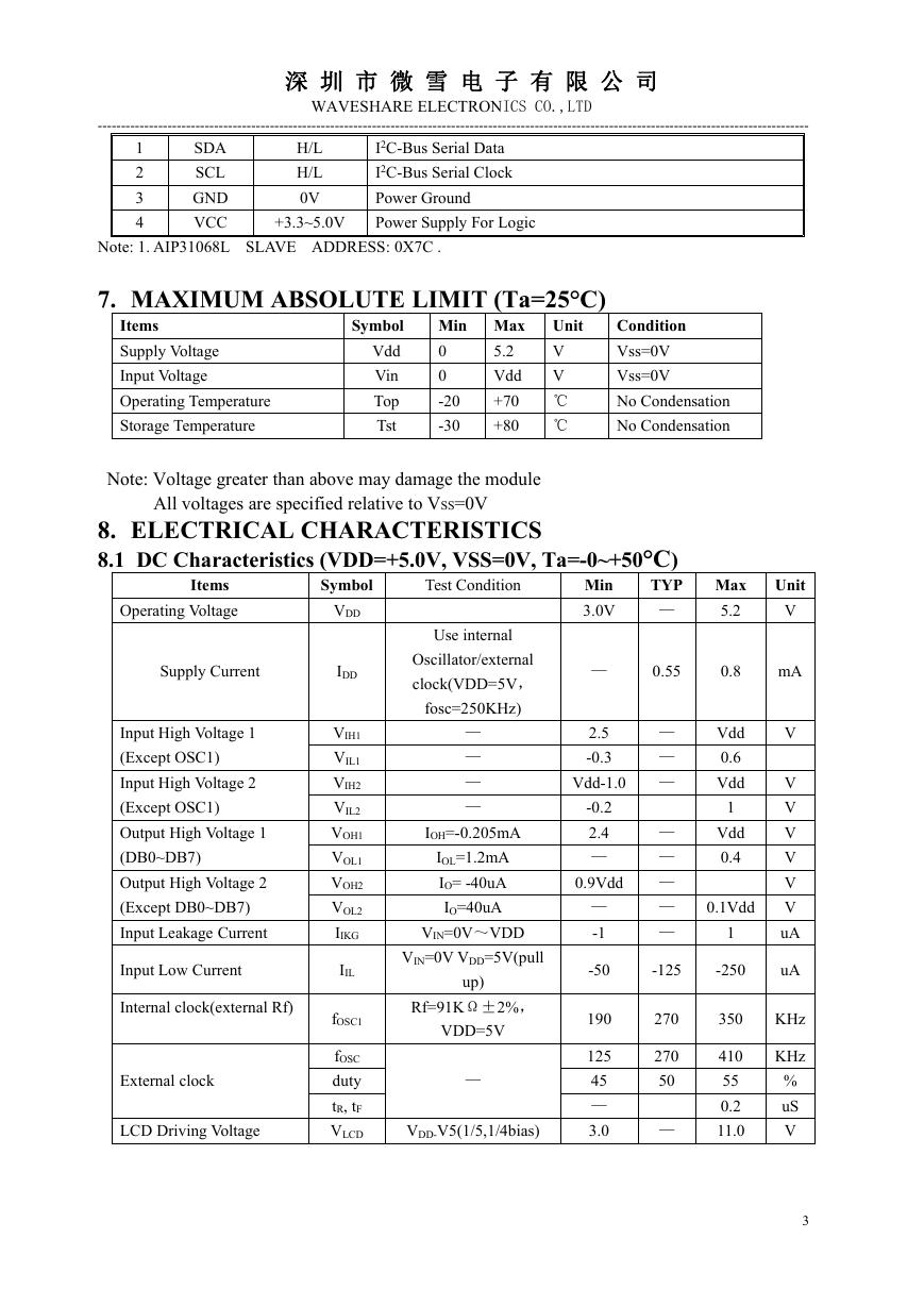
Note: 1. AIP31068L SLAVE ADDRESS: 0X7C .
7. MAXIMUM ABSOLUTE LIMIT (Ta=25°C)
Items
Supply Voltage
Input Voltage
Operating Temperature
Storage Temperature
Symbol
Vdd
Vin
Top
Tst
Min Max
0
0
-20
-30
5.2
Vdd
+70
+80
Unit
V
V
℃
℃
Condition
Vss=0V
Vss=0V
No Condensation
No Condensation
Note: Voltage greater than above may damage the module
All voltages are specified relative to VSS=0V
8. ELECTRICAL CHARACTERISTICS
8.1 DC Characteristics (VDD=+5.0V, VSS=0V, Ta=-0~+50°C)
TYP
—
Items
Operating Voltage
Test Condition
Min
3.0V
Symbol
VDD
Max
5.2
Unit
V
Supply Current
Input High Voltage 1
(Except OSC1)
Input High Voltage 2
(Except OSC1)
Output High Voltage 1
(DB0~DB7)
Output High Voltage 2
(Except DB0~DB7)
Input Leakage Current
Input Low Current
Internal clock(external Rf)
External clock
LCD Driving Voltage
IDD
VIH1
VIL1
VIH2
VIL2
VOH1
VOL1
VOH2
VOL2
IIKG
IIL
fOSC1
fOSC
duty
tR, tF
VLCD
Use internal
Oscillator/external
clock(VDD=5V,
fosc=250KHz)
—
—
—
—
IOH=-0.205mA
IOL=1.2mA
IO= -40uA
IO=40uA
VIN=0V~VDD
VIN=0V VDD=5V(pull
up)
Rf=91KΩ±2%,
VDD=5V
—
VDD-V5(1/5,1/4bias)
—
0.55
0.8
mA
2.5
-0.3
Vdd-1.0
-0.2
2.4
—
0.9Vdd
—
-1
-50
190
125
45
—
3.0
—
—
—
—
—
Vdd
0.6
Vdd
1
Vdd
0.4
—
— 0.1Vdd
—
1
-125
-250
270
270
50
—
350
410
55
0.2
11.0
V
V
V
V
V
V
V
uA
uA
KHz
KHz
%
uS
V
3
�
深 圳 市 微 雪 电 子 有 限 公 司
---------------------------------------------------------------------------------------------------------------------------------------------------------
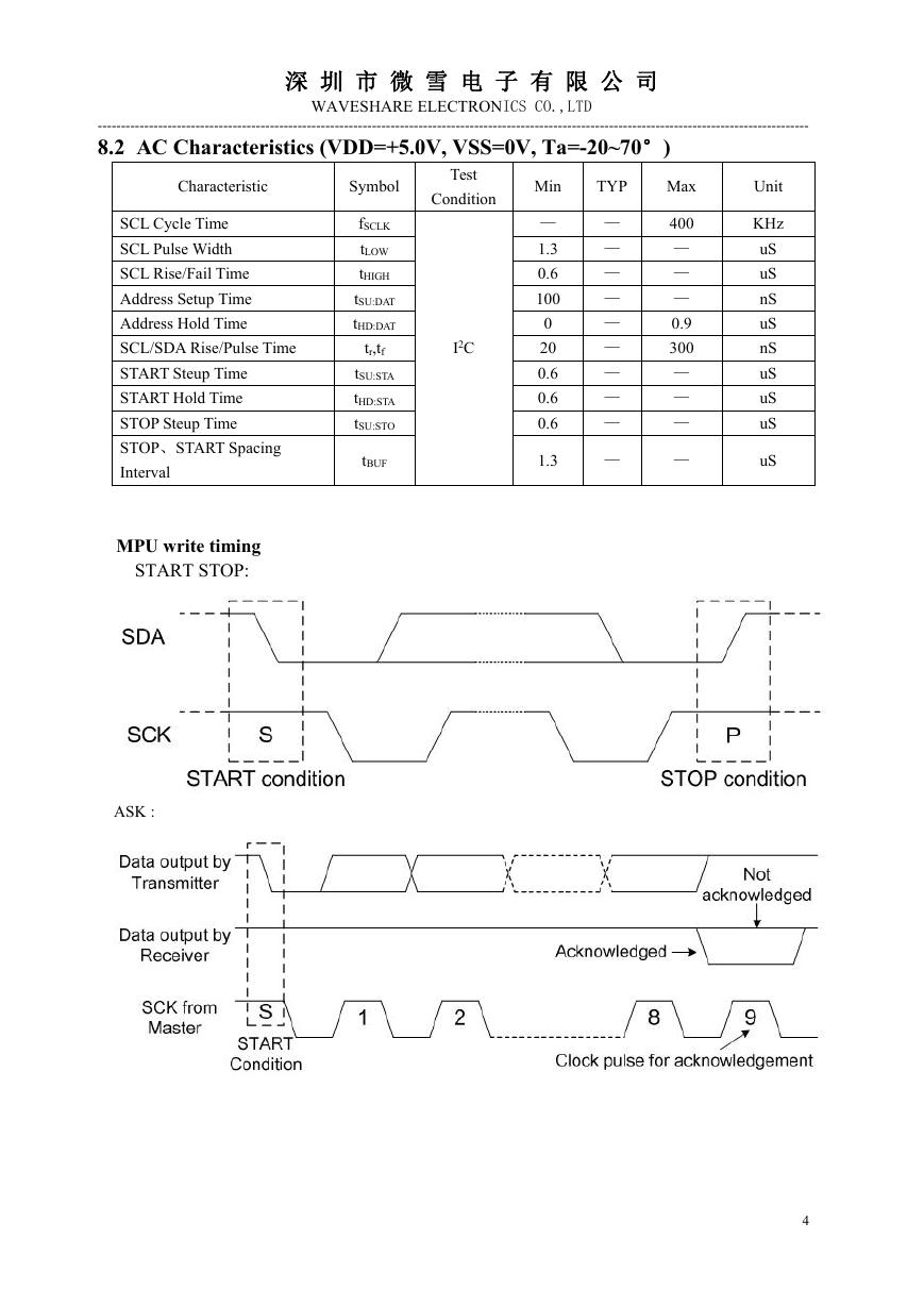
8.2 AC Characteristics (VDD=+5.0V, VSS=0V, Ta=-20~70°)
WAVESHARE ELECTRONICS CO.,LTD
Characteristic
Symbol
Test
Condition
Min
TYP
Max
fSCLK
tLOW
tHIGH
tSU:DAT
tHD:DAT
tr,tf
tSU:STA
tHD:STA
tSU:STO
tBUF
I2C
—
1.3
0.6
100
0
20
0.6
0.6
0.6
1.3
—
—
—
—
—
—
—
—
—
—
400
—
—
—
0.9
300
—
—
—
—
SCL Cycle Time
SCL Pulse Width
SCL Rise/Fail Time
Address Setup Time
Address Hold Time
SCL/SDA Rise/Pulse Time
START Steup Time
START Hold Time
STOP Steup Time
STOP、START Spacing
Interval
MPU write timing
START STOP:
ASK :
Unit
KHz
uS
uS
nS
uS
nS
uS
uS
uS
uS
4
�
深 圳 市 微 雪 电 子 有 限 公 司
---------------------------------------------------------------------------------------------------------------------------------------------------------
WAVESHARE ELECTRONICS CO.,LTD
AiP31068L (LCD ) Slave Address : 0X7C.
PCA9633DP2 (RGB) Slave Address: 0XC0.
9. FUNCTION SPECIFICATIONS
9.1. Basic Setting
To drive the LCD module corretly and provide normally display, please use the following
setting:
一 N=1, 2-line display
一 F=0, 5×8 dots font
一 D=1, display on
Note:
一 These setting/commands should issue to the LCD module while start up.
一 See the Display Commands section for details.
9.2. Resetting The LCD Module
When turning on the VDD and VSS power supply, LCD module will execute the reset routine
automatically. It takes about 50ms. After the reset routine, the LCD module status will be as
follow:
一 N=1, 2-line display
一 Display clear
一 DL=1, 8-bit interface
一 F=0, 5×8 dot character font
5
�
深 圳 市 微 雪 电 子 有 限 公 司
WAVESHARE ELECTRONICS CO.,LTD
---------------------------------------------------------------------------------------------------------------------------------------------------------
一 D=0, Display off
一 C=0, Cursor off
一 B=0, Blinking off
一 I/D=1, Increment by 1
一 S=0, No shift
NOTE:
一 Reset routine could not generate the Basic Setting
9.3. Display Memory Map
There are two main memory-areas in the LCD module for display.
一 Character Generator RAM(CGRAM)
一 Display Data RAM(DDRAM)
9.3.1. Character Generator RAM(CGRAM)
Character Generator RAM is for storing the User-defined Characters(5×8 dots font). Totally 8
User-defined Characters(character code = 00h-07h) could be created.
The User-defined Character Codes are 00h and 07h. They could be called into DDRAM as
normal character.
6
�
深 圳 市 微 雪 电 子 有 限 公 司
---------------------------------------------------------------------------------------------------------------------------------------------------------
WAVESHARE ELECTRONICS CO.,LTD
9.3.2. Character code ROM
Please refer to AiP31068L datasheet.
9.4. Display Commands
7
�
深 圳 市 微 雪 电 子 有 限 公 司
---------------------------------------------------------------------------------------------------------------------------------------------------------
WAVESHARE ELECTRONICS CO.,LTD
NOTE:
一 Do not use any other commands not listed, or the system malfunction may result.
一 For the details of rte display commands, please refer to AiP31068L datasheet.
10.DESIGN AND HANDING PRECAUTION
10.1.The LCD panel is made by glass. Any mechanical shock (eg. Dropping form high
place) will damage the LCD module.Do not add excessive force on the surface of the
display, which may cause the Display color change abnormally.
10.2.The polarizer on the LCD is easily get scratched. If possible, do not remove the LCD
protective film until the last step of installation.
10.3.Never attempt to disassemble or rework the LCD module.
10.4.Only Clean the LCD with Isopropyl Alcohol or Ethyl Alcohol. Other solvents (eg.
water) may damage the LCD.
distortion.
10.5.When mounting the LCD module, make sure that it is free form twisting, warping and
10.6.Ensure to provide enough space(with cushion) between case and LCD panel to
8
�


 V2版本原理图(Capacitive-Fingerprint-Reader-Schematic_V2).pdf
 摄像头工作原理.doc
 VL53L0X简要说明(En.FLVL53L00216).pdf
 原理图(DVK720-Schematic).pdf
 原理图(Pico-Clock-Green-Schdoc).pdf
 原理图(RS485-CAN-HAT-B-schematic).pdf
 File:SIM7500_SIM7600_SIM7800 Series_SSL_Application Note_V2.00.pdf
 ADS1263(Ads1262).pdf
 原理图(Open429Z-D-Schematic).pdf
 用户手册(Capacitive_Fingerprint_Reader_User_Manual_CN).pdf
 CY7C68013A(英文版)(CY7C68013A).pdf
 TechnicalReference_Dem.pdf