logo资料库

PCF8523数据手册(PCF8523).pdf

第1页 / 共78页
第2页 / 共78页
第3页 / 共78页
第4页 / 共78页
第5页 / 共78页
第6页 / 共78页
第7页 / 共78页
第8页 / 共78页
资料共78页,剩余部分请下载后查看
1. General description
2. Features and benefits
3. Applications
4. Ordering information
4.1 Ordering options
5. Marking
6. Block diagram
7. Pinning information
7.1 Pinning
7.2 Pin description
8. Functional description
8.1 Registers overview
8.2 Control and status registers
8.2.1 Register Control_1
8.2.2 Register Control_2
8.2.3 Register Control_3
8.3 Reset
8.4 Interrupt function
8.5 Power management functions
8.5.1 Standby mode
8.5.2 Battery switch-over function
8.5.2.1 Standard mode
8.5.2.2 Direct switching mode
8.5.2.3 Battery switch-over disabled, only one power supply (VDD)
8.5.3 Battery low detection function
8.6 Time and date registers
8.6.1 Register Seconds
8.6.1.1 Oscillator STOP flag
8.6.2 Register Minutes
8.6.3 Register Hours
8.6.4 Register Days
8.6.5 Register Weekdays
8.6.6 Register Months
8.6.7 Register Years
8.6.8 Data flow of the time function
8.7 Alarm registers
8.7.1 Register Minute_alarm
8.7.2 Register Hour_alarm
8.7.3 Register Day_alarm
8.7.4 Register Weekday_alarm
8.7.5 Alarm flag
8.7.6 Alarm interrupts
8.8 Register Offset
8.8.1 Correction when MODE = 0
8.8.2 Correction when MODE = 1
8.8.3 Offset calibration workflow
8.9 Timer function
8.9.1 Timer registers
8.9.1.1 Register Tmr_CLKOUT_ctrl and clock output
8.9.1.2 CLKOUT frequency selection
8.9.1.3 Register Tmr_A_freq_ctrl
8.9.1.4 Register Tmr_A_reg
8.9.1.5 Register Tmr_B_freq_ctrl
8.9.1.6 Register Tmr_B_reg
8.9.1.7 Programmable timer characteristics
8.9.2 Timer A
8.9.2.1 Watchdog timer function
8.9.2.2 Countdown timer function
8.9.3 Timer B
8.9.4 Second interrupt timer
8.9.5 Timer interrupt pulse
8.10 STOP bit function
8.11 I2C-bus interface
8.11.1 Bit transfer
8.11.2 START and STOP conditions
8.11.3 System configuration
8.11.4 Acknowledge
8.11.5 I2C-bus protocol
9. Internal circuitry
10. Safety notes
11. Limiting values
12. Static characteristics
13. Dynamic characteristics
14. Application information
14.1 Battery switch-over applications
15. Package outline
16. Bare die outline
17. Handling information
18. Packing information
18.1 Tape and reel information
18.2 Wafer and Film Frame Carrier (FFC) information for PCF8523U
19. Soldering of SMD packages
19.1 Introduction to soldering
19.2 Wave and reflow soldering
19.3 Wave soldering
19.4 Reflow soldering
20. Footprint information
21. Appendix
21.1 Real-Time Clock selection
22. Abbreviations
23. References
24. Revision history
25. Legal information
25.1 Data sheet status
25.2 Definitions
25.3 Disclaimers
25.4 Trademarks
26. Contact information
27. Tables
28. Figures
29. Contents
PCF8523 Real-Time Clock (RTC) and calendar Rev. 7 — 28 April 2015 Product data sheet 1. General description The PCF8523 is a CMOS1 Real-Time Clock (RTC) and calendar optimized for low power consumption. Data is transferred serially via the I2C-bus with a maximum data rate of 1000 kbit/s. Alarm and timer functions are available with the possibility to generate a wake-up signal on an interrupt pin. An offset register allows fine-tuning of the clock. The PCF8523 has a backup battery switch-over circuit, which detects power failures and automatically switches to the battery supply when a power failure occurs. For a selection of NXP Real-Time Clocks, see Table 56 on page 68 2. Features and benefits  Provides year, month, day, weekday, hours, minutes, and seconds based on a 32.768 kHz quartz crystal  Resolution: seconds to years  Clock operating voltage: 1.0 V to 5.5 V  Low backup current: typical 150 nA at VDD = 3.0 V and Tamb = 25 C  2 line bidirectional 1 MHz Fast-mode Plus (Fm+) I2C interface, read D1h, write D0h2  Battery backup input pin and switch-over circuit  Freely programmable timer and alarm with interrupt capability  Selectable integrated oscillator load capacitors for CL = 7 pF or CL = 12.5 pF  Oscillator stop detection function  Internal Power-On Reset (POR)  Open-drain interrupt or clock output pins  Programmable offset register for frequency adjustment 3. Applications  Time keeping application  Battery powered devices  Metering The definition of the abbreviations and acronyms used in this data sheet can be found in Section 22. 1. 2. Devices with other I2C-bus slave addresses can be produced on request.
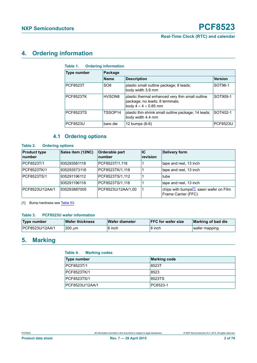
NXP Semiconductors 4. Ordering information PCF8523 Real-Time Clock (RTC) and calendar Table 1. Type number Ordering information Package Name SO8 PCF8523T PCF8523TK HVSON8 PCF8523TS TSSOP14 PCF8523U bare die 4.1 Ordering options Description plastic small outline package; 8 leads; body width 3.9 mm plastic thermal enhanced very thin small outline package; no leads; 8 terminals; body 4  4  0.85 mm plastic thin shrink small outline package; 14 leads; body width 4.4 mm 12 bumps (6-6) Version SOT96-1 SOT909-1 SOT402-1 PCF8523U Ordering options Sales item (12NC) Orderable part Table 2. Product type number PCF8523T/1 PCF8523TK/1 PCF8523TS/1 PCF8523U/12AA/1 935293581118 935293573118 935291196112 935291196118 935293887005 number PCF8523T/1,118 PCF8523TK/1,118 PCF8523TS/1,112 PCF8523TS/1,118 PCF8523U/12AA/1,00 IC revision 1 1 1 1 1 Delivery form tape and reel, 13 inch tape and reel, 13 inch tube tape and reel, 13 inch chips with bumps[1], sawn wafer on Film Frame Carrier (FFC) [1] Bump hardness see Table 53. Table 3. Type number PCF8523U/12AA/1 PCF8523U wafer information Wafer thickness 200 m 5. Marking Wafer diameter 6 inch FFC for wafer size 8 inch Marking of bad die wafer mapping Marking codes Table 4. Type number PCF8523T/1 PCF8523TK/1 PCF8523TS/1 PCF8523U/12AA/1 Marking code 8523T 8523 8523TS PC8523-1 PCF8523 Product data sheet All information provided in this document is subject to legal disclaimers. Rev. 7 — 28 April 2015 © NXP Semiconductors N.V. 2015. All rights reserved. 2 of 78
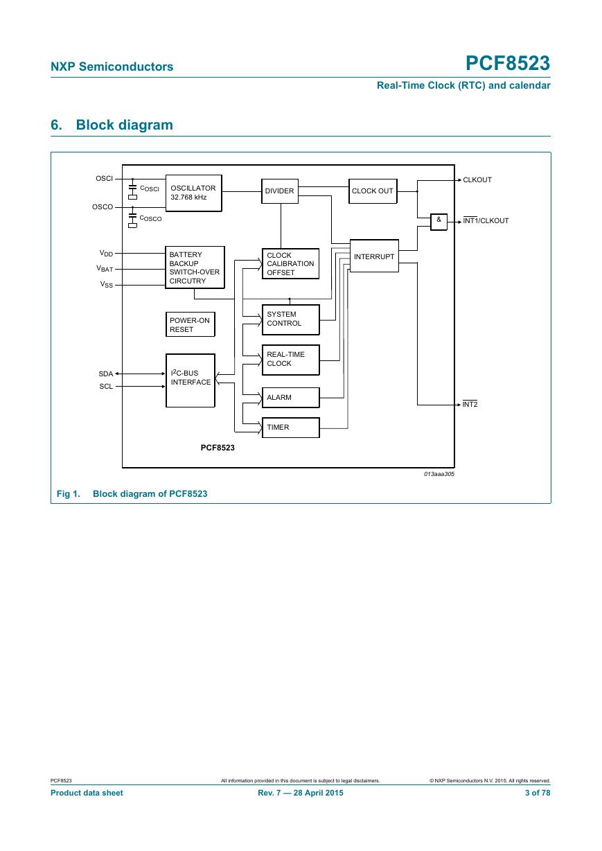
NXP Semiconductors 6. Block diagram PCF8523 Real-Time Clock (RTC) and calendar Fig 1. Block diagram of PCF8523 PCF8523 Product data sheet All information provided in this document is subject to legal disclaimers. Rev. 7 — 28 April 2015 © NXP Semiconductors N.V. 2015. All rights reserved. 3 of 78
NXP Semiconductors 7. Pinning information 7.1 Pinning PCF8523 Real-Time Clock (RTC) and calendar Top view. For mechanical details, see Figure 39 on page 56. Pin configuration for SO8 (PCF8523T) Fig 2. For mechanical details, see Figure 40 on page 57. Pin configuration for HVSON8 (PCF8523TK) Fig 3. Top view. For mechanical details, see Figure 41 on page 58. Pin configuration for TSSOP14 (PCF8523TS) Fig 4. PCF8523 Product data sheet All information provided in this document is subject to legal disclaimers. Rev. 7 — 28 April 2015 © NXP Semiconductors N.V. 2015. All rights reserved. 4 of 78
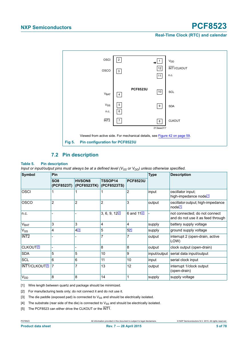
NXP Semiconductors PCF8523 Real-Time Clock (RTC) and calendar Viewed from active side. For mechanical details, see Figure 42 on page 59. Pin configuration for PCF8523U Fig 5. 7.2 Pin description Pin description Table 5. Input or input/output pins must always be at a defined level (VSS or VDD) unless otherwise specified. Symbol Type Description Pin SO8 (PCF8523T) 1 2 - 3 4 - 2 - 3 4[3] - - 5 6 7 8 OSCI OSCO n.c. VBAT VSS INT2 CLKOUT[5] - 5 SDA 6 SCL INT1/CLKOUT[5] 7 VDD 8 HVSON8 (PCF8523TK) 1 TSSOP14 (PCF8523TS) 1 PCF8523U 2 3 input output 2 3, 6, 9, 12[2] 6 and 11[2] - oscillator input; high-impedance node[1] oscillator output; high-impedance node[1] not connected; do not connect and do not use it as feed through battery supply voltage ground supply voltage interrupt 2 (open-drain, active LOW) clock output (open-drain) supply supply output output input/output serial data input/output input output serial clock input interrupt 1/clock output (open-drain) supply voltage supply 4 5 7 8 10 11 13 14 4 5[4] 7 8 9 10 12 1 [1] Wire length between quartz and package should be minimized. [2] For manufacturing tests only; do not connect it and do not use it. [3] The die paddle (exposed pad) is connected to VSS and should be electrically isolated. [4] The substrate (rear side of the die) is connected to VSS and should be electrically isolated. [5] The PCF8523 can either drive the CLKOUT or the INT1. PCF8523 Product data sheet All information provided in this document is subject to legal disclaimers. Rev. 7 — 28 April 2015 © NXP Semiconductors N.V. 2015. All rights reserved. 5 of 78
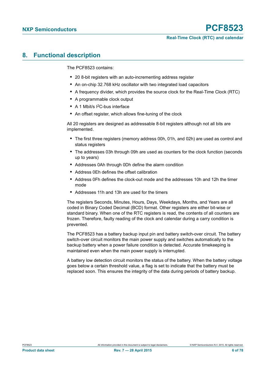
NXP Semiconductors 8. Functional description PCF8523 Real-Time Clock (RTC) and calendar The PCF8523 contains: • 20 8-bit registers with an auto-incrementing address register • An on-chip 32.768 kHz oscillator with two integrated load capacitors • A frequency divider, which provides the source clock for the Real-Time Clock (RTC) • A programmable clock output • A 1 Mbit/s I2C-bus interface • An offset register, which allows fine-tuning of the clock All 20 registers are designed as addressable 8-bit registers although not all bits are implemented. • The first three registers (memory address 00h, 01h, and 02h) are used as control and status registers • The addresses 03h through 09h are used as counters for the clock function (seconds up to years) • Addresses 0Ah through 0Dh define the alarm condition • Address 0Eh defines the offset calibration • Address 0Fh defines the clock-out mode and the addresses 10h and 12h the timer mode • Addresses 11h and 13h are used for the timers The registers Seconds, Minutes, Hours, Days, Weekdays, Months, and Years are all coded in Binary Coded Decimal (BCD) format. Other registers are either bit-wise or standard binary. When one of the RTC registers is read, the contents of all counters are frozen. Therefore, faulty reading of the clock and calendar during a carry condition is prevented. The PCF8523 has a battery backup input pin and battery switch-over circuit. The battery switch-over circuit monitors the main power supply and switches automatically to the backup battery when a power failure condition is detected. Accurate timekeeping is maintained even when the main power supply is interrupted. A battery low detection circuit monitors the status of the battery. When the battery voltage goes below a certain threshold value, a flag is set to indicate that the battery must be replaced soon. This ensures the integrity of the data during periods of battery backup. PCF8523 Product data sheet All information provided in this document is subject to legal disclaimers. Rev. 7 — 28 April 2015 © NXP Semiconductors N.V. 2015. All rights reserved. 6 of 78
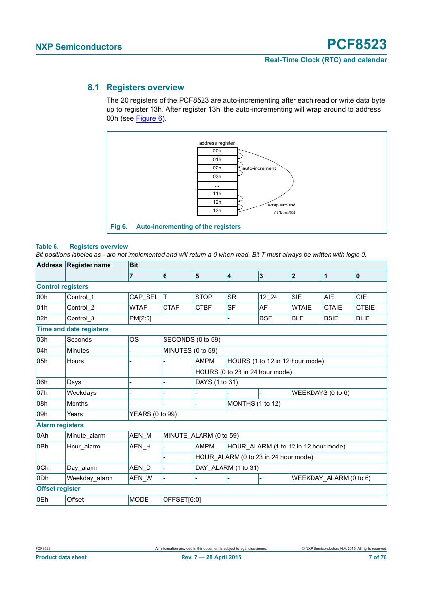
NXP Semiconductors PCF8523 Real-Time Clock (RTC) and calendar 8.1 Registers overview The 20 registers of the PCF8523 are auto-incrementing after each read or write data byte up to register 13h. After register 13h, the auto-incrementing will wrap around to address 00h (see Figure 6). Fig 6. Auto-incrementing of the registers Registers overview Table 6. Bit positions labeled as - are not implemented and will return a 0 when read. Bit T must always be written with logic 0. Address Register name 6 5 CAP_SEL T WTAF PM[2:0] CTAF STOP CTBF 4 SR SF - 3 2 1 0 12_24 AF BSF SIE WTAIE BLF AIE CTAIE BSIE CIE CTBIE BLIE SECONDS (0 to 59) MINUTES (0 to 59) AMPM - HOURS (0 to 23 in 24 hour mode) DAYS (1 to 31) - - - MONTHS (1 to 12) - HOURS (1 to 12 in 12 hour mode) WEEKDAYS (0 to 6) - - - YEARS (0 to 99) - - - AEN_M AEN_H MINUTE_ALARM (0 to 59) - - AEN_D - AEN_W - AMPM HOUR_ALARM (0 to 23 in 24 hour mode) DAY_ALARM (1 to 31) - - - HOUR_ALARM (1 to 12 in 12 hour mode) WEEKDAY_ALARM (0 to 6) MODE OFFSET[6:0] Bit 7 OS - - Control_1 Control_2 Control_3 Control registers 00h 01h 02h Time and date registers 03h 04h 05h Seconds Minutes Hours 06h Days 07h Weekdays 08h Months 09h Years Alarm registers 0Ah 0Bh Minute_alarm Hour_alarm Day_alarm Weekday_alarm 0Ch 0Dh Offset register 0Eh Offset PCF8523 Product data sheet All information provided in this document is subject to legal disclaimers. Rev. 7 — 28 April 2015 © NXP Semiconductors N.V. 2015. All rights reserved. 7 of 78
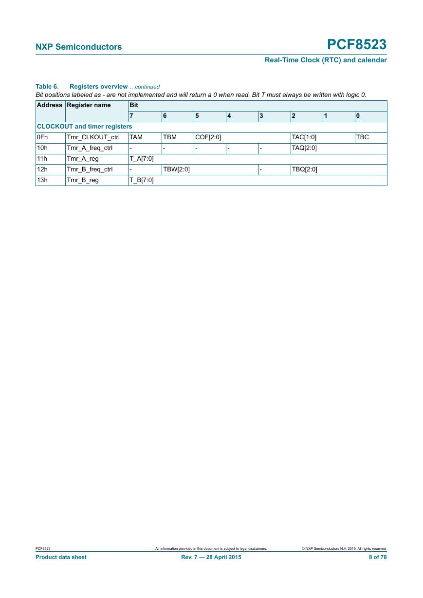
NXP Semiconductors PCF8523 Real-Time Clock (RTC) and calendar Registers overview …continued Table 6. Bit positions labeled as - are not implemented and will return a 0 when read. Bit T must always be written with logic 0. Address Register name Bit 7 CLOCKOUT and timer registers 0Fh 10h 11h 12h 13h Tmr_CLKOUT_ctrl Tmr_A_freq_ctrl Tmr_A_reg Tmr_B_freq_ctrl Tmr_B_reg TAM - T_A[7:0] - T_B[7:0] 6 5 TBM - COF[2:0] - 4 - TBW[2:0] 3 - - 2 1 TAC[1:0] TAQ[2:0] TBQ[2:0] 0 TBC PCF8523 Product data sheet All information provided in this document is subject to legal disclaimers. Rev. 7 — 28 April 2015 © NXP Semiconductors N.V. 2015. All rights reserved. 8 of 78
分享到:
收藏