PixArt Imaging Inc.
PAJ7620U2 General Datasheet
Integrated Gesture Recognition Sensor
PAJ7620U2: Integrated Gesture Recognition Sensor
General Description
The PAC7620 integrates gesture recognition function
with general I2C interface into a single chip forming an
image analytic sensor system. It can recognize 9 human
hand gesticulations such as moving up, down, left, right,
forward, backward, circle-clockwise, circle-counter
clockwise, and waving. It also offers built-in proximity
detection in sensing approaching or departing object
from the sensor. The PAC7620 is designed with great
flexibility in power-saving mechanism, well suit for low
power battery operated HMI devices. The PAJ7620 is
packaged into module form in-built with IR LED and optics
lens as a complete sensor solution
Key Features
Gesture/Cursor/Image modes
Built-in proximity detection
Gesture speed is 60~600°/s in Normal Mode and
60~1200°/s in Gaming Mode
Flexible power saving scheme
Communication interface options
I2C (for Gesture/Cursor mode)
4-wire SPI (for Image mode)
I2C interface up to 400 Kbit/s
SPI interface range from
22~48 MHz (Frame subtraction mode)
44~48 MHz (Raw data mode)
Ambient light immunity
Ambient light noise cancellation
Applications
PAD Phone
Tablet Personal Computer
Automobile Application
Key Parameters
Parameter
Array Size
Pixel Size
Max Frame Rate
Input Clock
Supply Voltage
Current
Consumption
Value
60x60 pixels
20x20 µm2
720 fps @ 240 report rate
22MHz for SPI Image Out
44MHz for SPI raw data mode
VDD: 2.8~3.6V
VBUS: 1.8~3.3V
VLED: 3.0~4.2V
Operation State:2.82 mA
Standby 1 State: 2.3mA
Standby 2 State: 1.5mA
Package Dimensions 5.2x3x1.88 mm3
Ordering Information
Part Number
Package Type
PAJ7620U2
13-pins LGA Module
For any additional inquiries, please contact us at
http://www.pixart.com/contact.asp.
Version 1.0 | 29 Mar 2016 | 41002AEN
PixArt Imaging Inc. http://www.pixart.com
All rights reserved. Any portion in this paper shall not be reproduced, copied, or transformed to any other forms without permission.
1
�
PixArt Imaging Inc.
Table of Contents
PAJ7620U2 General Datasheet
Integrated Gesture Recognition Sensor
1.1
1.2
1.3
1.4
1.5
2.1
2.2
2.3
3.0
4.0
PAJ7620U2: Integrated Gesture Recognition Sensor ............................................................................................................ 1
General Description .............................................................................................................................................................. 1
Key Features ......................................................................................................................................................................... 1
Applications .......................................................................................................................................................................... 1
Key Parameters ..................................................................................................................................................................... 1
Ordering Information ............................................................................................................................................................ 1
List of Figures ........................................................................................................................................................................... 3
1.0
Sensor Overview .......................................................................................................................................................... 4
Gesture Mode ......................................................................................................................................................... 4
Image Mode ............................................................................................................................................................ 4
Architecture Block Diagram ..................................................................................................................................... 4
Signal Description .................................................................................................................................................... 5
Pin Configuration ..................................................................................................................................................... 5
2.0 Mechanical Specifications ............................................................................................................................................ 6
Package Dimension ................................................................................................................................................. 6
Recommend Mechanical Design ............................................................................................................................. 7
Recommended IR Ink Spectrum .............................................................................................................................. 9
Reference Schematics ................................................................................................................................................ 10
Sensor Specifications ................................................................................................................................................. 11
Absolute Maximum Ratings, TA = 27°C .................................................................................................................. 11
Recommended Operating Condition ..................................................................................................................... 11
Electrical Specifications, VDD=2.8V, TA = 27°C ........................................................................................................ 12
Gesture Functional Specifications ......................................................................................................................... 13
Interface AC Specifications .................................................................................................................................... 13
Register Tables ........................................................................................................................................................... 14
Register Bank Select .............................................................................................................................................. 14
Image Size Setting ................................................................................................................................................. 14
Setting 30x30 Pixels Image Output Mode ............................................................................................................. 14
AE/AG Controls ...................................................................................................................................................... 15
GPIO Setting .......................................................................................................................................................... 15
Interrupt Controls .................................................................................................................................................. 16
Gesture Mode Controls ......................................................................................................................................... 17
Cursor Mode Controls ........................................................................................................................................... 20
Proximity Mode Controls ....................................................................................................................................... 20
EFuse Program Controls ........................................................................................................................................ 21
Background Controls ............................................................................................................................................. 22
Lens Shading Compensation .................................................................................................................................. 22
5.1
5.2
5.3
5.4
5.5
5.6
5.7
5.8
5.9
5.10
5.11
5.12
4.1
4.2
4.3
4.4
4.5
5.0
Version 1.0 | 29 Mar 2016 | 41002AEN
PixArt Imaging Inc. http://www.pixart.com
All rights reserved. Any portion in this paper shall not be reproduced, copied, or transformed to any other forms without permission.
2
�
PixArt Imaging Inc.
PAJ7620U2 General Datasheet
Integrated Gesture Recognition Sensor
5.13
5.14
5.15
5.16
5.17
5.18
5.19
LED Controls .......................................................................................................................................................... 22
Sleep Mode ........................................................................................................................................................... 23
Clock Controls ........................................................................................................................................................ 24
Chip/Version ID...................................................................................................................................................... 24
Suspend/Reset ....................................................................................................................................................... 24
Test Mode ............................................................................................................................................................. 25
Reserved Registers List .......................................................................................................................................... 25
Document Revision History .................................................................................................................................................... 28
List of Figures
Figure 1. Architecture Block Diagram ...................................................................................................................................... 4
Figure 2. PAJ7620U2 Module Pin Configuration (BTM VIEW) .................................................................................................. 5
Figure 3. PAJ7620U2 Package Outline Diagram ....................................................................................................................... 6
Figure 4. PAJ7620U2 Mechanical Design Guide ....................................................................................................................... 7
Figure 5. PAJ7620U2 Mechanical Design Guide (IR Ink Suggestion) ........................................................................................ 8
Figure 6. IR Ink Spectrum ......................................................................................................................................................... 9
Figure 7. PAJ7620U2 Application Circuit ................................................................................................................................ 10
List of Tables
Table 1. Gesture Detecting Range and View Angle .................................................................................................................. 4
Table 2. Signal Description ....................................................................................................................................................... 5
Table 3. PAJ7620U2 Pin Definition ........................................................................................................................................... 5
Version 1.0 | 29 Mar 2016 | 41002AEN
PixArt Imaging Inc. http://www.pixart.com
All rights reserved. Any portion in this paper shall not be reproduced, copied, or transformed to any other forms without permission.
3
�
PixArt Imaging Inc.
PAJ7620U2 General Datasheet
Integrated Gesture Recognition Sensor
1.0 Sensor Overview
1.1 Gesture Mode
For Gesture Mode, there are 9 gestures recognition being embedded in the sensor including move up, move down, move
left, move right, move forward, move backward, circle-clockwise, circle-counter clockwise, and wave. These gestures
information can be simply accessed by register reading via I2C bus. The normal gesture detecting range from 5 to 15 cm
from where PAC7620 is located through the operating view angle of diagonally 60° respectively. Additionally, The PAC7620
can be configured as Normal Mode (Gesture speed is 60°/s - 600°/s) or Gaming Mode (Gesture speed is 60°/s - 1200°/s) for
different applications. The PAC7620 also offer built-in proximity detection for the purpose of sensing object approaching or
departing.
Table 1. Gesture Detecting Range and View Angle
Part Number
Detecting Range
View Angle (Diagonal)
PAJ7620U2
5 to 15 cm
60°
Image Mode
1.2
For image mode, the typical report rate is 120Hz with image size equals 30x30 (Frame subtraction mode, WOI) or 30x30
(Raw data mode, WOI). The depth of pixel data depth is 9 bit and output through the SPI bus. The SCK rate of SPI bus equals
to the external SPI clock input ranging from 22 to 48 MHz (Frame subtraction mode) or 44 to 48 MHz (Raw data mode). By
programming the internal register set via I2C serial control bus, it performs on-chip report rate, exposure time, gain
adjustment, array skip mode, and array average mode.
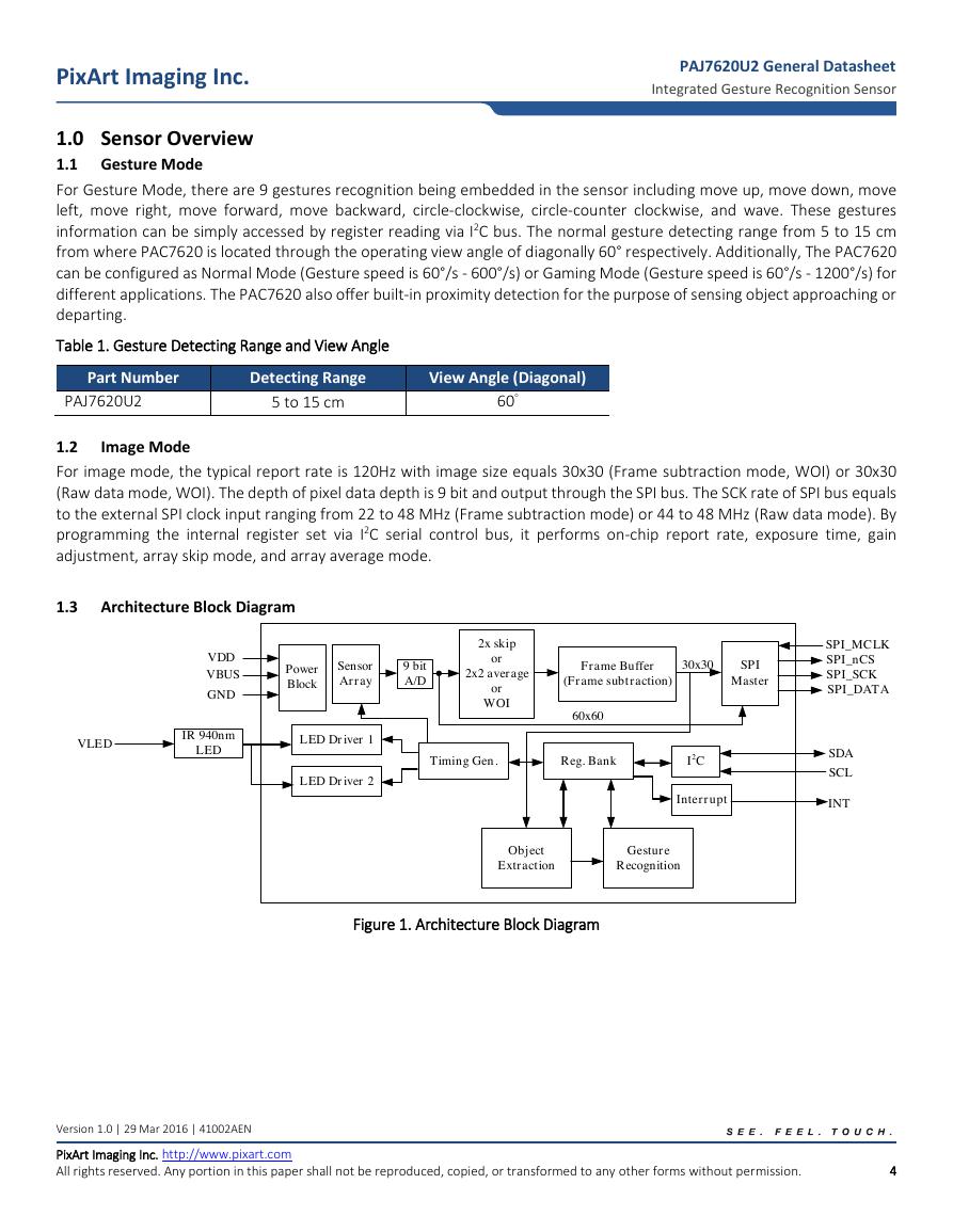
1.3 Architecture Block Diagram
Figure 1. Architecture Block Diagram
Version 1.0 | 29 Mar 2016 | 41002AEN
PixArt Imaging Inc. http://www.pixart.com
All rights reserved. Any portion in this paper shall not be reproduced, copied, or transformed to any other forms without permission.
4
Sensor Array9 bitA/DSPIMasterTiming Gen.Reg. BankI2CPower BlockSDASCLVDDGNDSPI_MCLKSPI_nCSSPI_SCKSPI_DATAFrame Buffer(Frame subtraction)30x30IR 940nm LEDLED Driver 1LED Driver 260x602x skipor2x2 averageorWOIVBUSVLEDObject ExtractionGesture RecognitionInterruptINT�
PAJ7620U2 General Datasheet
Integrated Gesture Recognition Sensor
PixArt Imaging Inc.
1.4
Signal Description
Table 2. Signal Description
Signal Name
SDA
SCL
INT_N
GPIO3(SPI_DATA)
GPIO2(SPI_SCK)
GPIO1(SPI_nCS)
GPIO0(SPI_MCLK)
Description
I2C data pin
I2C clk pin
Interrupt pin (Active low) for Gesture Mode.
Data out of SPI master for image mode
SCK signal of SPI master for image mode
nCS signal of SPI master for image mode
External clock input of SPI master for image mode
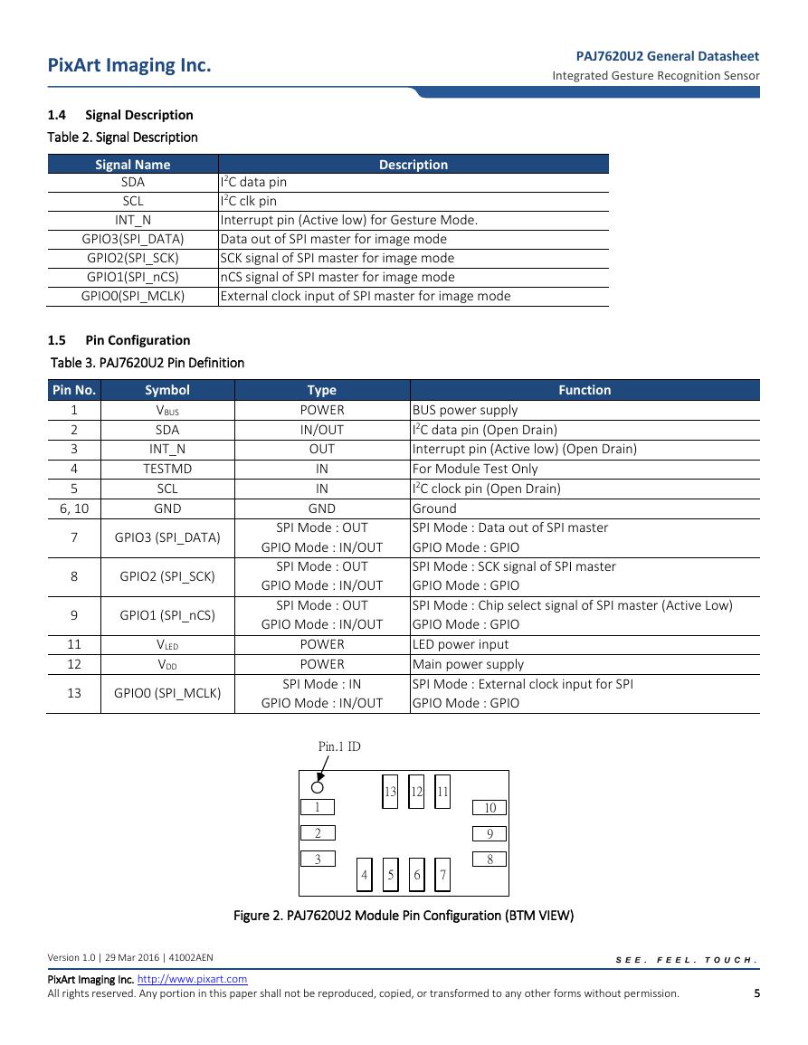
1.5 Pin Configuration
Table 3. PAJ7620U2 Pin Definition
Pin No.
1
2
3
4
5
6, 10
7
8
9
11
12
13
Symbol
VBUS
SDA
INT_N
TESTMD
SCL
GND
Type
POWER
IN/OUT
OUT
IN
IN
GND
GPIO3 (SPI_DATA)
GPIO2 (SPI_SCK)
GPIO1 (SPI_nCS)
VLED
VDD
GPIO0 (SPI_MCLK)
SPI Mode : OUT
GPIO Mode : IN/OUT
SPI Mode : OUT
GPIO Mode : IN/OUT
SPI Mode : OUT
GPIO Mode : IN/OUT
POWER
POWER
SPI Mode : IN
GPIO Mode : IN/OUT
Function
BUS power supply
I2C data pin (Open Drain)
Interrupt pin (Active low) (Open Drain)
For Module Test Only
I2C clock pin (Open Drain)
Ground
SPI Mode : Data out of SPI master
GPIO Mode : GPIO
SPI Mode : SCK signal of SPI master
GPIO Mode : GPIO
SPI Mode : Chip select signal of SPI master (Active Low)
GPIO Mode : GPIO
LED power input
Main power supply
SPI Mode : External clock input for SPI
GPIO Mode : GPIO
Figure 2. PAJ7620U2 Module Pin Configuration (BTM VIEW)
Version 1.0 | 29 Mar 2016 | 41002AEN
PixArt Imaging Inc. http://www.pixart.com
All rights reserved. Any portion in this paper shall not be reproduced, copied, or transformed to any other forms without permission.
5
10981234576131211Pin.1 ID�
PixArt Imaging Inc.
2.0 Mechanical Specifications
2.1 Package Dimension
PAJ7620U2 General Datasheet
Integrated Gesture Recognition Sensor
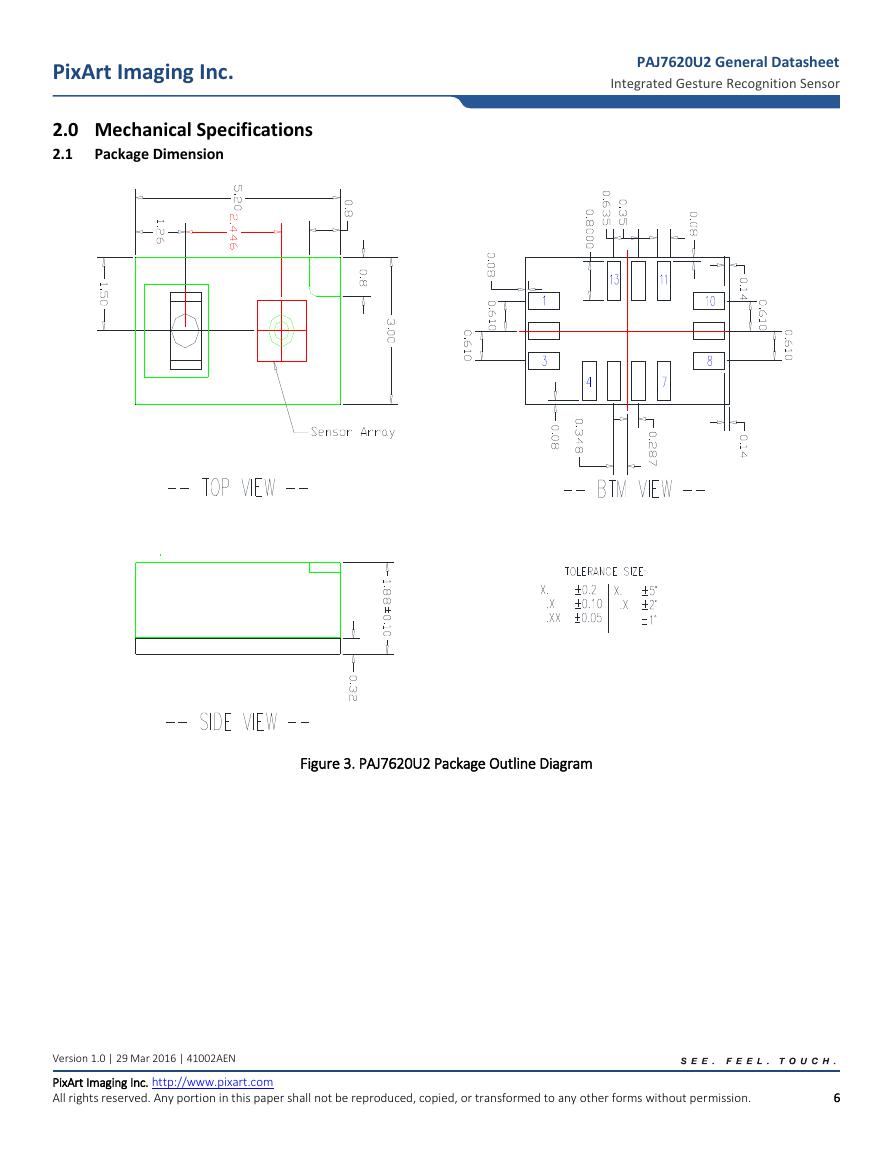
Figure 3. PAJ7620U2 Package Outline Diagram
Version 1.0 | 29 Mar 2016 | 41002AEN
PixArt Imaging Inc. http://www.pixart.com
All rights reserved. Any portion in this paper shall not be reproduced, copied, or transformed to any other forms without permission.
6
�
PixArt Imaging Inc.
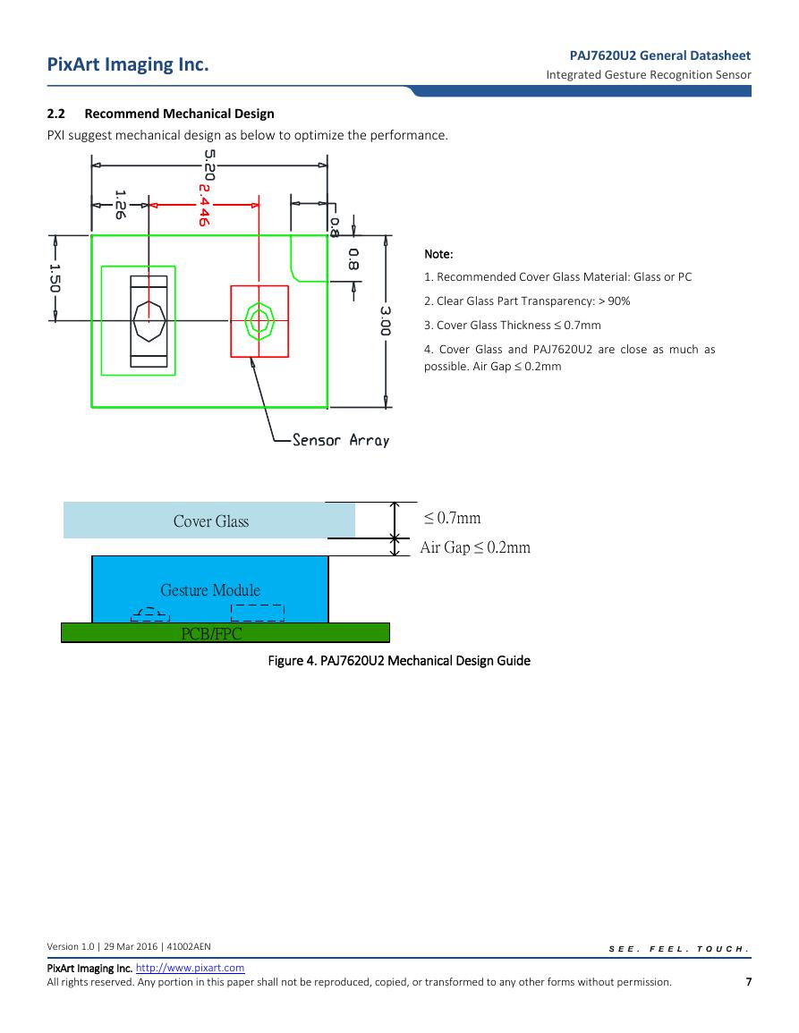
2.2 Recommend Mechanical Design
PXI suggest mechanical design as below to optimize the performance.
PAJ7620U2 General Datasheet
Integrated Gesture Recognition Sensor
Note:
1. Recommended Cover Glass Material: Glass or PC
2. Clear Glass Part Transparency: > 90%
3. Cover Glass Thickness 0.7mm
4. Cover Glass and PAJ7620U2 are close as much as
possible. Air Gap 0.2mm
Figure 4. PAJ7620U2 Mechanical Design Guide
Version 1.0 | 29 Mar 2016 | 41002AEN
PixArt Imaging Inc. http://www.pixart.com
All rights reserved. Any portion in this paper shall not be reproduced, copied, or transformed to any other forms without permission.
7
Gesture ModulePCB/FPCCover GlassAir Gap ≤ 0.2mm≤ 0.7mm PixArt Imaging Inc.�
PixArt Imaging Inc.
PAJ7620U2 General Datasheet
Integrated Gesture Recognition Sensor
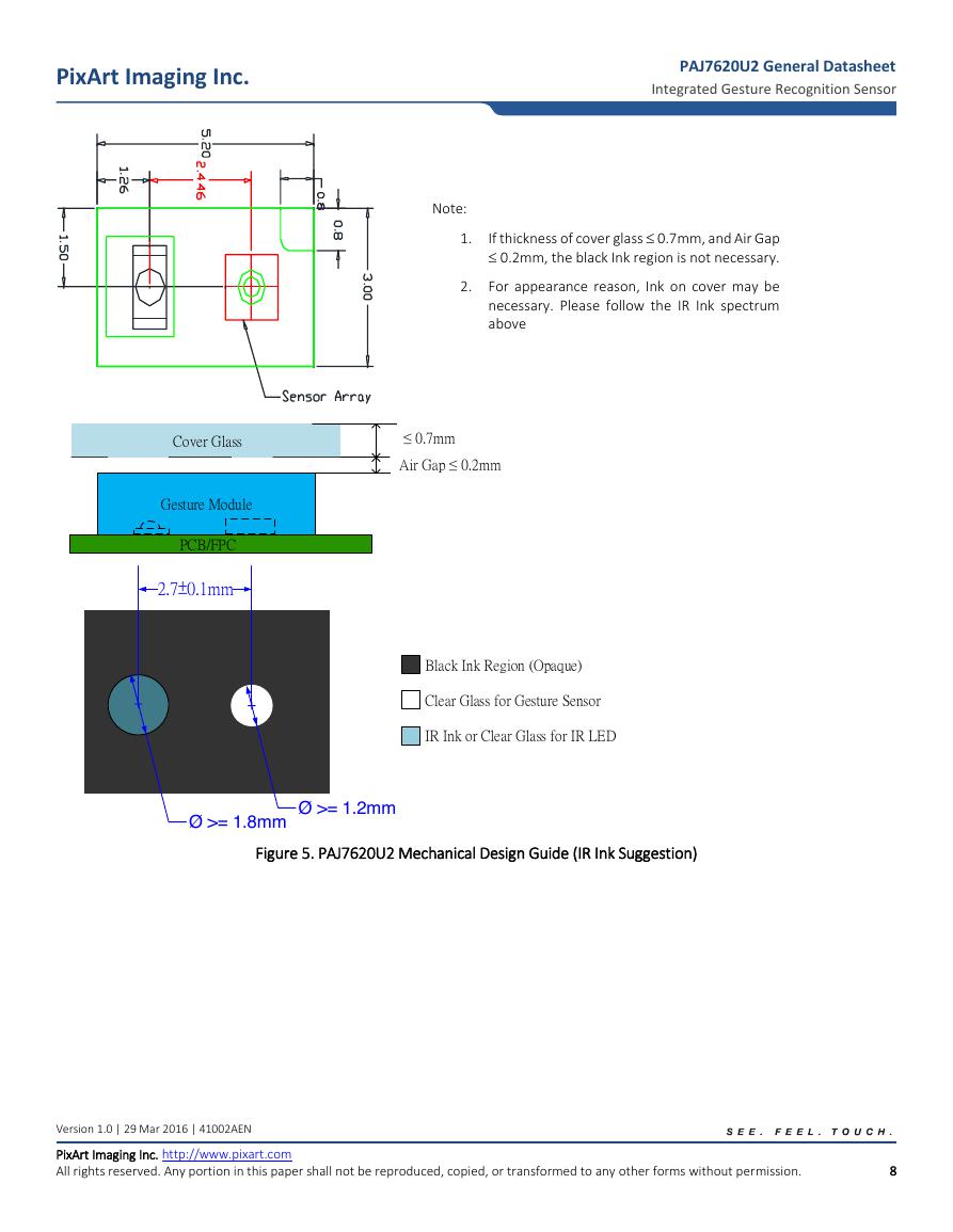
Note:
1.
If thickness of cover glass 0.7mm, and Air Gap
0.2mm, the black Ink region is not necessary.
2. For appearance reason, Ink on cover may be
necessary. Please follow the IR Ink spectrum
above
Figure 5. PAJ7620U2 Mechanical Design Guide (IR Ink Suggestion)
Version 1.0 | 29 Mar 2016 | 41002AEN
PixArt Imaging Inc. http://www.pixart.com
All rights reserved. Any portion in this paper shall not be reproduced, copied, or transformed to any other forms without permission.
8
Gesture ModulePCB/FPCCover GlassAir Gap ≤ 0.2mm≤ 0.7mm PixArt Imaging Inc.2.7±0.1mmØ >= 1.2mmØ >= 1.8mmBlack Ink Region (Opaque)Clear Glass for Gesture SensorIR Ink or Clear Glass for IR LED�


 V2版本原理图(Capacitive-Fingerprint-Reader-Schematic_V2).pdf
 摄像头工作原理.doc
 VL53L0X简要说明(En.FLVL53L00216).pdf
 原理图(DVK720-Schematic).pdf
 原理图(Pico-Clock-Green-Schdoc).pdf
 原理图(RS485-CAN-HAT-B-schematic).pdf
 File:SIM7500_SIM7600_SIM7800 Series_SSL_Application Note_V2.00.pdf
 ADS1263(Ads1262).pdf
 原理图(Open429Z-D-Schematic).pdf
 用户手册(Capacitive_Fingerprint_Reader_User_Manual_CN).pdf
 CY7C68013A(英文版)(CY7C68013A).pdf
 TechnicalReference_Dem.pdf