Desktop 3 Microfilmer
A-61036
Part No. 4C2063 User’s Guide
Safety Information for the Kodak Desktop 3 Microfilmer
IMPORTANT: Equipment shall be installed by qualified
personnel.
WARNING: Dangerous voltage. Disconnect the main
power before installation.
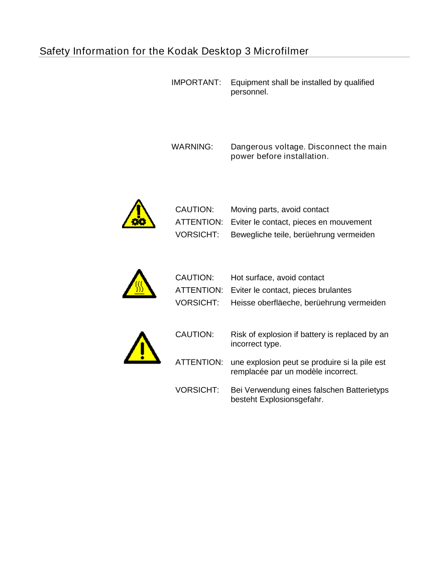
CAUTION: Moving parts, avoid contact
ATTENTION: Eviter le contact, pieces en mouvement
VORSICHT: Bewegliche teile, berüehrung vermeiden
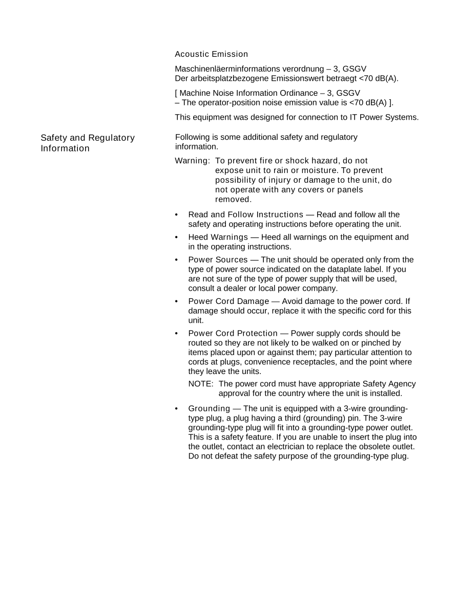
CAUTION: Hot surface, avoid contact
ATTENTION: Eviter le contact, pieces brulantes
VORSICHT: Heisse oberfläeche, berüehrung vermeiden
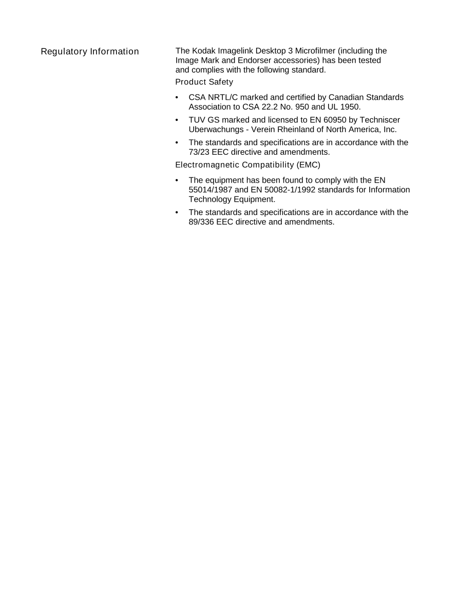
CAUTION: Risk of explosion if battery is replaced by an
incorrect type.
ATTENTION: une explosion peut se produire si la pile est
remplacée par un modèle incorrect.
VORSICHT: Bei Verwendung eines falschen Batterietyps
besteht Explosionsgefahr.
Acoustic Emission
Maschinenläerminformations verordnung – 3, GSGV
Der arbeitsplatzbezogene Emissionswert betraegt <70 dB(A).
[ Machine Noise Information Ordinance – 3, GSGV
– The operator-position noise emission value is <70 dB(A) ].
This equipment was designed for connection to IT Power Systems.
Safety and Regulatory Following is some additional safety and regulatory
Information information.
Warning: To prevent fire or shock hazard, do not
expose unit to rain or moisture. To prevent
possibility of injury or damage to the unit, do
not operate with any covers or panels
removed.
• Read and Follow Instructions — Read and follow all the
safety and operating instructions before operating the unit.
• Heed Warnings — Heed all warnings on the equipment and
in the operating instructions.
• Power Sources — The unit should be operated only from the
type of power source indicated on the dataplate label. If you
are not sure of the type of power supply that will be used,
consult a dealer or local power company.
• Power Cord Damage — Avoid damage to the power cord. If
damage should occur, replace it with the specific cord for this
unit.
• Power Cord Protection — Power supply cords should be
routed so they are not likely to be walked on or pinched by
items placed upon or against them; pay particular attention to
cords at plugs, convenience receptacles, and the point where
they leave the units.
NOTE: The power cord must have appropriate Safety Agency
approval for the country where the unit is installed.
• Grounding — The unit is equipped with a 3-wire grounding-
type plug, a plug having a third (grounding) pin. The 3-wire
grounding-type plug will fit into a grounding-type power outlet.
This is a safety feature. If you are unable to insert the plug into
the outlet, contact an electrician to replace the obsolete outlet.
Do not defeat the safety purpose of the grounding-type plug.
Regulatory Information The Kodak Imagelink Desktop 3 Microfilmer (including the
Image Mark and Endorser accessories) has been tested
and complies with the following standard.
Product Safety
• CSA NRTL/C marked and certified by Canadian Standards
Association to CSA 22.2 No. 950 and UL 1950.
• TUV GS marked and licensed to EN 60950 by Techniscer
Uberwachungs - Verein Rheinland of North America, Inc.
• The standards and specifications are in accordance with the
73/23 EEC directive and amendments.
Electromagnetic Compatibility (EMC)
• The equipment has been found to comply with the EN
55014/1987 and EN 50082-1/1992 standards for Information
Technology Equipment.
• The standards and specifications are in accordance with the
89/336 EEC directive and amendments.
Introduction
The Kodak Desktop 3 Microfilmer is intended for medium-to low-volume
operations that require rapid, high-reduction microfilming. Documents up
to 9.00 inches (22.9 cm) wide and 11.7 inches (29.7 cm) long can be
microfilmed, with images captured on 16 mm film at a 40:1 reduction
ratio.
Thick-base (5 mil) film cassettes accept 100 ft. (30.5 m) lengths of
microfilm. Thin-base (2.5 mil) film cassettes accept 215 ft. (65.5 m)
lengths. A choice of duplex or duo modes provide flexibility in
microfilming.
Documents to be microfilmed are placed in the automatic feeder in the
front of the unit, photographed as they pass between two clear document
guides, and exit into an adjustable receiving area at the upper front of the
microfilmer.
No special skills or knowledge are required to operate the Desktop 3
Microfilmer.
A-61036 July 2000 1
1 Overview
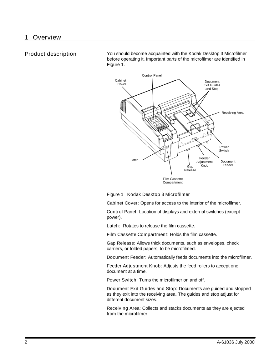
Product description You should become acquainted with the Kodak Desktop 3 Microfilmer
before operating it. Important parts of the microfilmer are identified in
Figure 1.
Control Panel
Cabinet Document
Cover Exit Guides
and Stop
Receiving Area
Power
Switch
Latch Feeder
Adjustment Document
Gap Knob Feeder
Release
Film Cassette
Compartment
Figure 1 Kodak Desktop 3 Microfilmer
Cabinet Cover: Opens for access to the interior of the microfilmer.
Control Panel: Location of displays and external switches (except
power).
Latch: Rotates to release the film cassette.
Film Cassette Compartment: Holds the film cassette.
Gap Release: Allows thick documents, such as envelopes, check
carriers, or folded papers, to be microfilmed.
Document Feeder: Automatically feeds documents into the microfilmer.
Feeder Adjustment Knob: Adjusts the feed rollers to accept one
document at a time.
Power Switch: Turns the microfilmer on and off.
Document Exit Guides and Stop: Documents are guided and stopped
as they exit into the receiving area. The guides and stop adjust for
different document sizes.
Receiving Area: Collects and stacks documents as they are ejected
from the microfilmer.
2 A-61036 July 2000
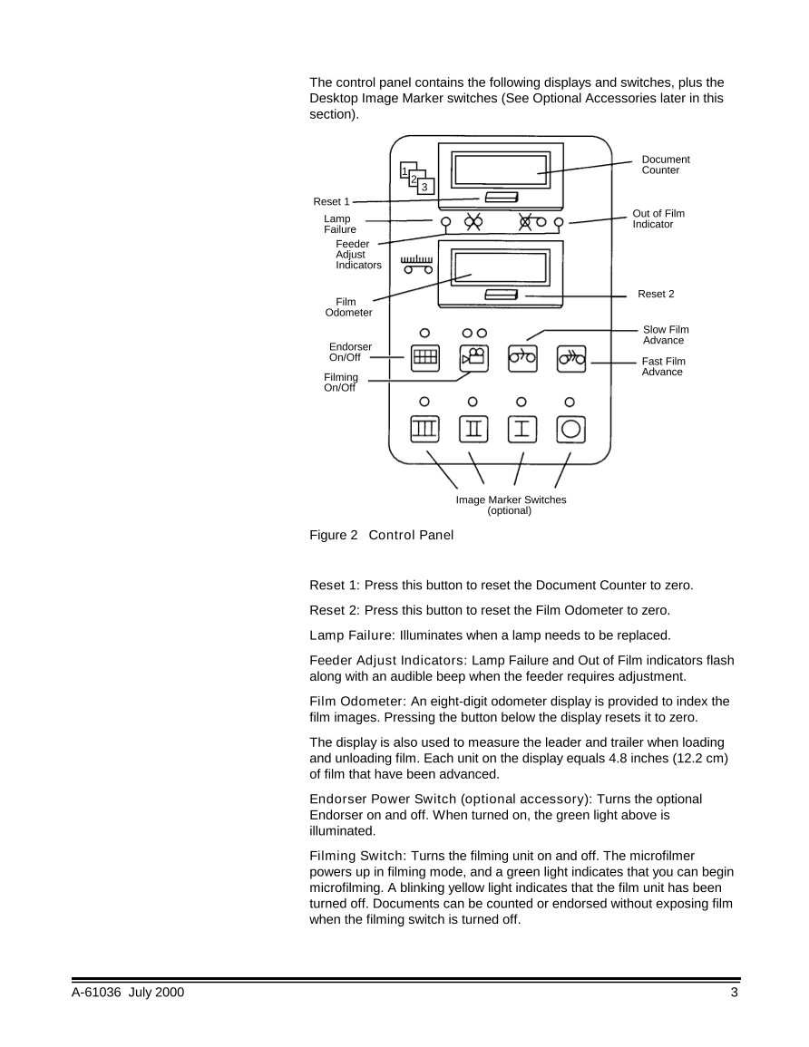
The control panel contains the following displays and switches, plus the
Desktop Image Marker switches (See Optional Accessories later in this
section).
Document
1 Counter
2
3
Reset 1
Lamp Out of Film
Failure Indicator
Feeder
Adjust
Indicators
Reset 2
Film
Odometer
Slow Film
Endorser Advance
On/Off Fast Film
Filming Advance
On/Off
Image Marker Switches
(optional)
Figure 2 Control Panel
Reset 1: Press this button to reset the Document Counter to zero.
Reset 2: Press this button to reset the Film Odometer to zero.
Lamp Failure: Illuminates when a lamp needs to be replaced.
Feeder Adjust Indicators: Lamp Failure and Out of Film indicators flash
along with an audible beep when the feeder requires adjustment.
Film Odometer: An eight-digit odometer display is provided to index the
film images. Pressing the button below the display resets it to zero.
The display is also used to measure the leader and trailer when loading
and unloading film. Each unit on the display equals 4.8 inches (12.2 cm)
of film that have been advanced.
Endorser Power Switch (optional accessory): Turns the optional
Endorser on and off. When turned on, the green light above is
illuminated.
Filming Switch: Turns the filming unit on and off. The microfilmer
powers up in filming mode, and a green light indicates that you can begin
microfilming. A blinking yellow light indicates that the film unit has been
turned off. Documents can be counted or endorsed without exposing film
when the filming switch is turned off.
A-61036 July 2000 3
Document Counter: An eight-digit counter that shows how many
documents have been processed by the microfilmer. Pressing the button
below the display resets the counter to zero. It is possible to count
documents without microfilming them (See Filming Switch on the
previous page).
Out of Film Indicator: Illuminates when the film supply is almost empty.
Slow Film Advance: Advances film at approximately 7 inches (17.8 cm)
per second when this switch is pressed. Film is automatically advanced
1.5 to 2.0 inches (3.8 cm to 5.1 cm) when the microfilmer is turned on or
when a different film cassette is installed.
Fast Film Advance Switch: Advances film approximately 48 inches
(121.9 cm) when pressed. Used when the operator loads and unloads
film.
Image Marker Switches: By pressing one of these optional switches,
you can determine the size of the image mark placed adjacent to each
film image. III = large; II - medium; I = small; 0 = none.
Alarm and interlocks Built-in alarms and interlocks provide safe and reliable operation and
contribute to high-quality microfilm images.
• An alarm sounds and a light is illuminated when the filming switch is on
and the film supply is low or empty.
• A blinking light above the filming switch indicates that filming is shut off.
• An alarm sounds, a light is illuminated, and the microfilmer transport
shuts off automatically if either of the exposure lamps fail.
• The microfilmer transport shuts off automatically if a document
becomes lodged in the document conveyor system.
• The microfilmer will not operate when the cabinet cover is open.
• Operator-replaceable fuses, mounted in the rear of the microfilmer,
shut off the microfilmer in the event of an electrical overload.
• An alarm sounds and the top two lights on the control panel flash if the
document spacing becomes too close, and the feeder needs
adjustment.
4 A-61036 July 2000




 V2版本原理图(Capacitive-Fingerprint-Reader-Schematic_V2).pdf
 摄像头工作原理.doc
 VL53L0X简要说明(En.FLVL53L00216).pdf
 原理图(DVK720-Schematic).pdf
 原理图(Pico-Clock-Green-Schdoc).pdf
 原理图(RS485-CAN-HAT-B-schematic).pdf
 File:SIM7500_SIM7600_SIM7800 Series_SSL_Application Note_V2.00.pdf
 ADS1263(Ads1262).pdf
 原理图(Open429Z-D-Schematic).pdf
 用户手册(Capacitive_Fingerprint_Reader_User_Manual_CN).pdf
 CY7C68013A(英文版)(CY7C68013A).pdf
 TechnicalReference_Dem.pdf