Freescale Semiconductor
Application Note
Document Number: AN4249
Rev. 1.0, 11/2015
Accuracy of Angle Estimation in
eCompass and 3D Pointer
Applications
1
2
3
4
5
6
7
8
Introduction . . . . . . . . . . . . . . . . . . . . . . . . . . . . . . . . . . . 1
1.1 Related Information . . . . . . . . . . . . . . . . . . . . . . . . . 2
1.2 Key Words . . . . . . . . . . . . . . . . . . . . . . . . . . . . . . . . 2
1.3 Summary . . . . . . . . . . . . . . . . . . . . . . . . . . . . . . . . . 2
Angle Estimation in the eCompass and 3D Pointer. . . . . 3
Accelerometer Induced Errors in Roll and Pitch Angles . 3
Instabilities in Roll and Pitch Angle Estimation . . . . . . . . 5
Accelerometer Induced Errors in the Compass Angle. . . 8
Hard-Iron Magnetic Calibration Induced Errors
in Compass Angle . . . . . . . . . . . . . . . . . . . . . . . . . . . . . 10
Soft-Iron Magnetic Calibration Induced Errors
in Compass Angle . . . . . . . . . . . . . . . . . . . . . . . . . . . . . 11
Extension to Time Varying Sensor Errors . . . . . . . . . . . 14
8.1 Accelerometer Zero-g Offset . . . . . . . . . . . . . . . . . 14
8.2 Magnetometer Zero-Field Offset . . . . . . . . . . . . . . 14
8.3 Accelerometer Noise Figure . . . . . . . . . . . . . . . . . 14
8.4 Magnetometer Noise Figure . . . . . . . . . . . . . . . . . 15
8.5 Sensor Noise Statistics . . . . . . . . . . . . . . . . . . . . . 15
8.6 Effects of Digital Filtering. . . . . . . . . . . . . . . . . . . . 16
by: Talat Ozyagcilar
Applications Engineer
Introduction
1
This application note addresses the relationship between
errors in the outputs from accelerometer and
magnetometer sensors and the resulting errors in the roll,
pitch and yaw angles computed by a tilt-compensated
eCompass or 3D Pointer application.
The mathematical approach continues that developed in
Freescale Application Notes AN4248 “Implementing a
Tilt-Compensated eCompass using Accelerometer and
Magnetometer Sensors”, AN4246 “Calibrating an
eCompass in the Presence of Hard- and Soft-Iron
Interference” and AN4247 “Layout Recommendations
for PCBs Using a Magnetometer Sensor”. It is
recommended that these are read first to provide the
mathematical foundation for this document.
The error analysis starts by determining the relationship
between accelerometer errors and errors in the estimated
roll and pitch angles. The consequent error in compass
angle is then derived from the roll and pitch angle errors.
Expressions are then derived for the errors in the
compass heading angle resulting from errors in the
© 2013, 2015 Freescale Semiconductor, Inc. All rights reserved.
�
Introduction
magnetometer sensor and the hard- and soft-iron calibration. The final section extends the discussion to
the statistics of time varying sensor outputs.
To avoid unnecessarily complex phrasing, the term “compass heading” is used throughout to refer to the
yaw angle. Where small angle approximations are used, it should be assumed that the angle is measured
in radians.
Related Information
1.1
C source code and additional documentation are available for download at
www.freescale.com/sensorfusion.
Key Words
1.2
Accelerometer, Magnetometer, eCompass, 3D Pointer, Angle Error, Hard Iron, Soft Iron.
1.3
Summary
• The accelerometer sensor output is used by the tilt-compensated eCompass algorithms to compute
the roll and pitch angles. Errors in the accelerometer output therefore create errors in the computed
roll and pitch angles. With a small angle approximation, the roll and pitch angle errors are roughly
equal to the ratio of the accelerometer errors to the gravitational acceleration g.
• Errors in the estimated roll and pitch angles lead to an error in the estimated compass angle. With
a small angle approximation, the compass angle error is approximately equal to the square root of
the sum of the squares of the roll and pitch angle errors.
• An instability in the roll angle calculation exists when the PCB is held at a pitch angle closer to
vertical than the ratio of the z-channel accelerometer error to g. This leads directly to an instability
in the compass angle if workarounds are not deployed.
• The sum of the magnetometer zero field offset and the hard- and soft-iron magnetic interference
created by ferromagnetic components on the PCB will typically dominate the geomagnetic field
and completely jam an eCompass if software calibration algorithms are not deployed.
• Any inaccuracy in the estimated magnetometer zero field offset and hard-iron calibration will leave
a residual fixed magnetic offset which manifests as a compass heading error varying sinusoidally
with one error cycle per 360° rotation in compass heading. The amplitude of this compass heading
error is equal to the ratio of the square root of the sum of the squares of the residual hard-iron error
to the horizontal geomagnetic field component.
• Any inaccuracy in the soft-iron calibration will leave a residual directional distortion of the
geomagnetic field which manifests as a compass heading error also varying sinusoidally with
compass heading but with two error cycles per 360° rotation in compass heading.
Accuracy of Angle Estimation in eCompass and 3D Pointer Applications, Rev. 1.0
2
Sensor
Freescale Semiconductor, Inc.
�
Angle Estimation in the eCompass and 3D Pointer
2
Angle Estimation in the eCompass and 3D Pointer
The tilt-compensated eCompass uses the combination of a three axis accelerometer and a three axis
magnetometer in a six degree of freedom system. Calibration algorithms correct the magnetometer
readings for hard- and soft-iron interference generated by ferromagnetic components on the PCB. The
accelerometer output is used to correct the magnetometer output in roll and pitch angles after which the
final compass heading is computed.
Since the tilt-compensated eCompass algorithms compute all three roll, pitch and compass angles, the
eCompass can also be used to implement a 3D remote control pointer. Typically the compass heading and
pitch angles are used to define the pointing direction in the horizontal and vertical axes respectively. Full
details are provided in application note AN4248.
3
Accelerometer Induced Errors in Roll and Pitch
Angles
This section calculates the errors in the computed roll φ and pitch θ angles as a function of errors in the
three accelerometer components.
Equation 3 in application note AN4248 gives the accelerometer output Gp at true orientation angles φ0 and
θ0 as a function of the rotation matrices Rx (φ0) and Ry (θ0) defined in AN4248 equations 5 and 6. Adding
an accelerometer error vector {ΔGpx, ΔGpy, ΔGpz} extends AN4248 equation 3 to:
Gp
=
Gpx
Gpy
Gpz
=
Rx
φ0(
)Ry θ0(
)
ΔGpx
0
ΔGpy
0
g
ΔGpz
+
=
g θ0
sin
sin
cos
–
g θ0 φ0
cos
g θ0 φ0
cos
Δ+ Gpx
Δ+ Gpy
ΔG+
pz
In application note AN4248, equation 13 defines the estimated roll angle φ in terms of the two
accelerometer components Gpy and Gpz.
tan
φ Gpy
--------
=
Gpz
Eqn. 1
Eqn. 2
Combining Equations 1 and 2 gives an explicit expression for the error Δφ in the estimated roll angle in
terms of four variables: the true pitch and roll orientation angles θ0, φ0 and the y- and z-channel
accelerometer errors ΔGpy, ΔGpz:
Δφ φ φ0–
=
=
tan 1– Gpy
--------
Gpz
–
φ0
=
φ0 ΔGpy
tan 1– g θ0
cos
φ0–
----------------------------------------------------
φ0 ΔGpz
g θ0
cos
sin
cos
+
+
Eqn. 3
For the special case where ΔGpz = 0 (no z-channel accelerometer noise) and θ0 = 0 (no pitch rotation),
Equation 3 simplifies to:
Δφ φ φ0–
=
=
tan 1– g φ0 ΔGpy
sin
φ0–
------------------------------------
+
g φ0
cos
Accuracy of Angle Estimation in eCompass and 3D Pointer Applications, Rev. 1.0
Sensor
Freescale Semiconductor, Inc.
Eqn. 4
3
�
Accelerometer Induced Errors in Roll and Pitch Angles
Application Note AN4248, equation 15 defines the estimated pitch angle θ in terms of the three
accelerometer components Gpx, Gpy and Gpz and the estimated roll angle φ:
Combining equations 1 and 5 gives the expression for the error Δθ in the estimated pitch angle:
tan
θ
=
Gpx
–
------------------------------------------------
Gpz φcos
Gpy φsin
+
Δθ
=
θ θ0–
tan 1–
=
θ0–
------------------------------------------------------------------------------------------------------------------------------------------------
) φcos
g θ0 φ0 ΔGpy
(
cos
g θ0 ΔGpx
sin
–
) φsin
(
g θ0 φ0 ΔGpz
cos
+
cos
sin
+
+
For the special case where ΔGpy = ΔGpz = 0 (no y- or z-channel accelerometer noise present) and
φ = φ0 = 0 (no roll rotation), Equation 6 simplifies to:
1– g θ0 ΔGpx
sin
θ0–
-----------------------------------
θ θ0–
tan=
Δθ
=
–
g θ0
cos
Eqn. 5
Eqn. 6
Eqn. 7
Equations 4 and 7 are identical in form, apart from a sign difference in the terms ΔGpx and ΔGpy. Figure 1
shows the form of both equations as a function of accelerometer error ΔGpx and ΔGpy, varying from 0 mg
to 100 mg. The peak error occurs near zero roll or pitch angle with value (in radians) equal to the ratio of
the accelerometer noise component to g.
Figure 1. Angle Error (degrees) for Gpy (Roll) and Gpx (Pitch) Errors
Equation 3 can be similarly simplified for the special cases of zero pitch angle θ0 = 0 and Equation 6 for
zero roll angle φ0 = 0 with accelerometer error in the z-axis only to give:
Δφ φ φ0–
=
tan 1–
=
g φ0
sin
+
φ0–
-------------------------------------
g φ0 ΔGpz
cos
Eqn. 8
Accuracy of Angle Estimation in eCompass and 3D Pointer Applications, Rev. 1.0
4
Sensor
Freescale Semiconductor, Inc.
�
Instabilities in Roll and Pitch Angle Estimation
Δθ θ θ0–
=
tan 1–
=
g θ0
sin
+
θ0–
-------------------------------------
g θ0 ΔGpz
cos
Eqn. 9
Equations 8 and 9 have a similar form and are plotted together in Figure 2 for the z-axis accelerometer
error ΔGpz varying between 0 and 100 mg. In this case, the z-axis accelerometer error has least impact at
flat orientation and has most impact at pitch and roll angles near 90o where the z-axis accelerometer
reading approaches zero and is dominated by the error ΔGpz. Using the relation tan-1(x) = π/2 - tan-1(1/x),
the error at 90° equals the ratio of the z-channel noise ΔGpz to g.
Figure 2. Error in Roll and Pitch Angle as a Function of Gpz Errors
Instabilities in Roll and Pitch Angle Estimation
4
The previous section determined the errors in the roll and pitch angle as a function of accelerometer errors
when the other angle (pitch or roll respectively) was zero. Figures 1 and 2 show that the errors in the
estimated angles are numerically well behaved in these special cases. This section investigates whether
there are orientations where the roll and pitch angles become unstable and infinitely sensitive to
accelerometer errors.
The estimated roll angle φ is defined by Equation 2 in terms of the measured y and z-accelerometer
outputs. Simple inspection of Equation 2 indicates that:
i) The estimated roll angle is well behaved for all Gpy, when Gpz is not near zero. Zero Gpy gives an
estimated roll angle of zero.
ii) The estimated roll angle is also well behaved for all Gpz, when Gpy is not near zero. Zero Gpz gives an
estimated roll angle of -90o or 90 o.
iii)The estimated roll angle is, however, unstable when both Gpy and Gpz are near zero. The estimated roll
angle is essentially random in the range -180o to 180o.
Accuracy of Angle Estimation in eCompass and 3D Pointer Applications, Rev. 1.0
Sensor
Freescale Semiconductor, Inc.
5
�
Instabilities in Roll and Pitch Angle Estimation
The third case corresponds to the eCompass pointed vertically upwards at 90o pitch angle or vertically
downwards at -90o pitch angle. The accelerometer is then insensitive to any rotation in roll since the roll
axis is aligned with the gravitation vector and both Gpy and Gpz are zero irrespective of roll angle.
Since the roll angle is used to de-rotate the magnetometer reading, the instability in the estimated roll angle
also leads directly to an instability in the compass angle.
This can be understood in the mathematics of the rotation matrix sequence defined in AN4248. Expanding
the product of the three rotation matrix sequence when the compass is vertical at θ0 = 90o gives:
Rx φ0(
)Ry θ0
π
Rz ψ0
---=
2
(
)
=
1
0
0
0
cos
sin–
φ0
φ0
0
φ0
sin
φ0
cos
0 0 1–
0 1 0
1 0 0
ψ0
ψ0
cos
sin–
0
ψ0
sin
ψ0
cos
0
0
0
1
Eqn. 10
=
0
ψ0 φ0–
(
)
sin–
(
)
ψ0 φ0–
cos
0
ψ0 φ0–
(
)
(
)
ψ0 φ0–
cos
sin
1–
0
0
=
Ry θ0
π
Rz ψ0 φ0–
---=
2
(
)
Eqn. 11
Equation 11 states that when the compass is vertical, any rotation in roll adds to compass angle. Any error
in the estimated roll angle therefore leads to an identical error in the estimated compass heading. The same
mathematics applies when the eCompass is pointing downwards at θ0 = -90o.
In practice this roll instability is more of a theoretical problem than a practical problem. A simple
workaround is to mix approximately 5% of Gpx into the denominator of Equation 2 in order to smoothly
drive the roll angle to zero at near vertical operation. This stabilizes the eCompass and has the additional
benefit of changing the compass pointing direction to align with the z-axis, exactly as would be expected
by a user holding up an eCompass vertically. Equation 2 with this workaround then becomes:
φtan
=
Gpy
+
with α 5%≈
----------------------------
Gpz αGpx
Eqn. 12
The pitch angle θ0 at which the calculation of the roll angle φ becomes unstable, assuming that the
workaround in Equation 12 is not used, is given by the z component of Equation 1 as:
θ0
=
cos 1– ΔGpz
------------
g
≈–
π
θ0
---
2
sin 1– ΔGpz
------------
g
=
ΔGpz
------------ for small θ0
g
Eqn. 13
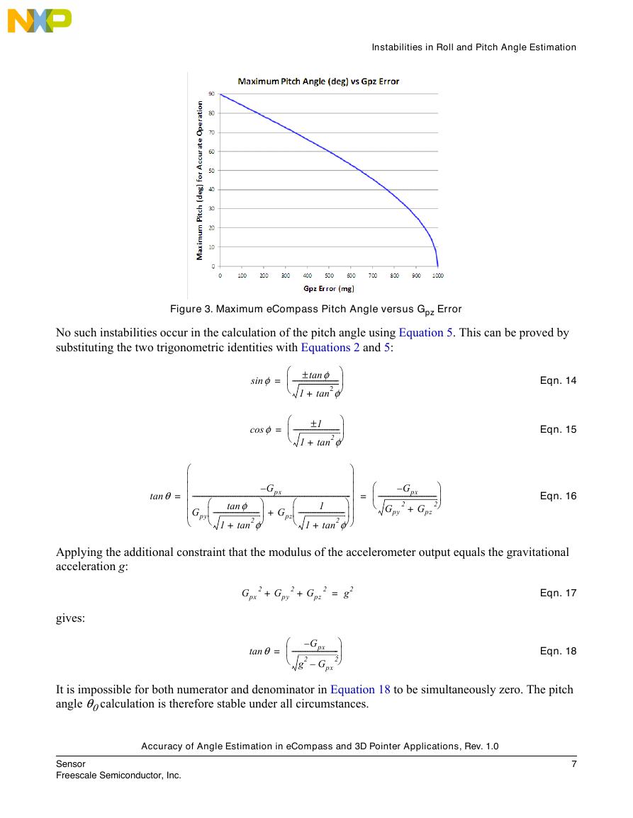
Equation 13 is plotted for θ0 in Figure 3. The behavior is physically realistic decreasing from 90o for no
accelerometer error to 0o as the z-channel error approaches 1g.
Accuracy of Angle Estimation in eCompass and 3D Pointer Applications, Rev. 1.0
6
Sensor
Freescale Semiconductor, Inc.
�
Instabilities in Roll and Pitch Angle Estimation
Figure 3. Maximum eCompass Pitch Angle versus Gpz Error
No such instabilities occur in the calculation of the pitch angle using Equation 5. This can be proved by
substituting the two trigonometric identities with Equations 2 and 5:
φsin
=
φtan±
---------------------------
tan2φ
1
+
φcos
=
1±
---------------------------
tan2φ
+
1
θtan
=
--------------------------------------------------------------------------------------------
1
---------------------------
Gpy
tan2φ
–
---------------------------
tan2φ
φtan
+
Gpx
1
+
+
Gpz
1
Eqn. 14
Eqn. 15
Eqn. 16
=
Gpx
–
----------------------------------
2
2 Gpz
Gpy
+
Applying the additional constraint that the modulus of the accelerometer output equals the gravitational
acceleration g:
gives:
Gpx
2 Gpy
+
2 Gpz
+
2
g2=
θtan
=
Gpx
–
---------------------------
2
g2 Gpx
–
Eqn. 17
Eqn. 18
It is impossible for both numerator and denominator in Equation 18 to be simultaneously zero. The pitch
angle θ0 calculation is therefore stable under all circumstances.
Accuracy of Angle Estimation in eCompass and 3D Pointer Applications, Rev. 1.0
Sensor
Freescale Semiconductor, Inc.
7
�
Accelerometer Induced Errors in the Compass Angle
Accelerometer Induced Errors in the Compass Angle
5
The previous sections have derived expressions for the errors in roll and pitch angles as a function of
accelerometer errors. These pitch and roll angle errors lead to an error in the compass angle even before
the magnetometer data is used.
AN4248 equation 4 gives the magnetometer output Bp (ignoring any magnetometer error and any hard- or
soft-iron interference for now) in terms of the true orientation angles and the magnetic inclination angle δ
as:
Bp
=
Bpx
Bpy
Bpz
= φ0(
Rx
)Ry θ0(
)Rz ψ0
(
)B
δcos
0
δsin
After correction for the estimated roll and pitch angles, the de-rotated magnetometer output is:
Ry θ–(
)Rx φ–(
)Bp
=
(
Ry θ0 θ–
)Rx φ0 φ–
)R
(
(
ψ0
)B
z
δcos
0
δsin
Ry=
Δθ–(
)Rx Δφ–(
)B
cos
sin–
ψ0 δcos
ψ0 δcos
δsin
≈
B
–
ψ0 δcos
Δθ δsin
+
ψ0 δ Δφ δsin
cos
–
Δθ ψ0 δ Δφ ψ0 δ
sin
cos
–
cos
sin–
cos
cos
δsin+
Eqn. 19
Eqn. 20
Eqn. 21
AN4248 equations 20 to 22 give an expression for the estimated compass angle ψ as the negative ratio of
the y and x tilt-compensated magnetometer readings. Substituting the components of Equation 21 gives:
tan
ψ
tan=
(
ψ0 Δψ+
)
=
Δφ δtan
sin
Δψ tan 1–
-----------------------------------------
=
Δθ δtan
cos
+
+
ψ0
ψ0
Δφ δtan
sin
ψ0–
-----------------------------------------
Δθ δtan
cos
ψ0
ψ0
+
+
Eqn. 22
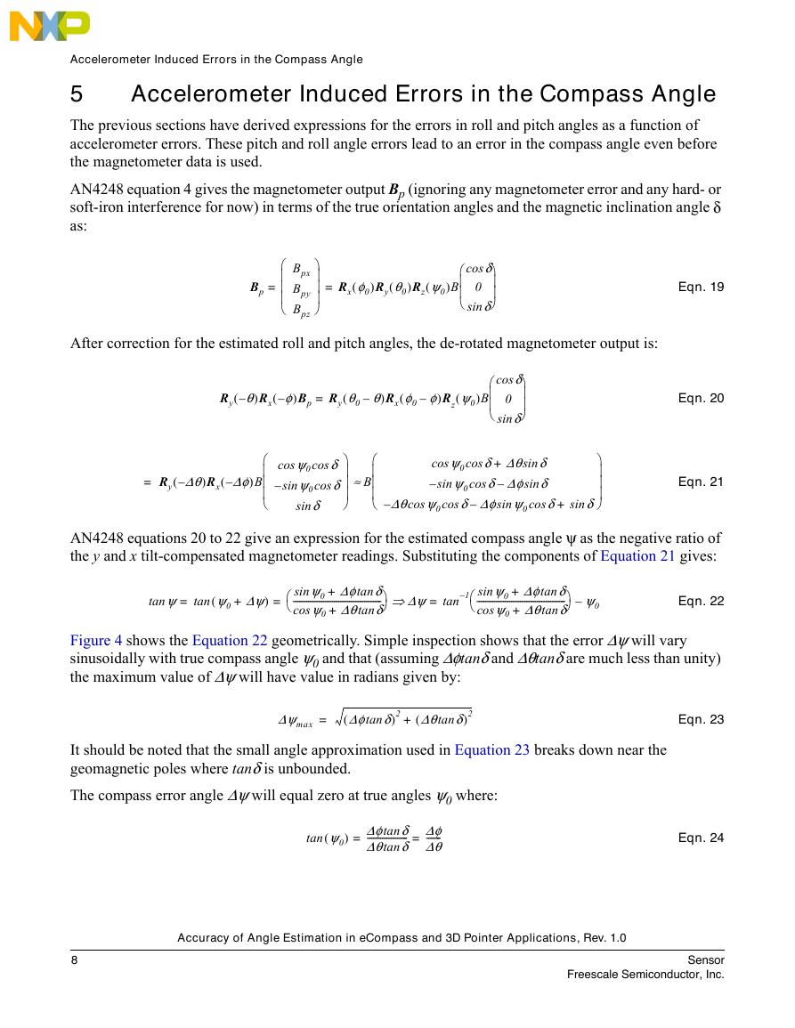
Figure 4 shows the Equation 22 geometrically. Simple inspection shows that the error Δψ will vary
sinusoidally with true compass angle ψ0 and that (assuming Δφtanδ and Δθtanδ are much less than unity)
the maximum value of Δψ will have value in radians given by:
Δψmax
=
(
Δφ δtan
)2 Δθ δtan
)2
+
(
It should be noted that the small angle approximation used in Equation 23 breaks down near the
geomagnetic poles where tanδ is unbounded.
The compass error angle Δψ will equal zero at true angles ψ0 where:
tan
(
ψ0
) Δφ δtan
-------------------
=
=
Δθ δtan
Δφ
Δθ-------
Eqn. 23
Eqn. 24
Accuracy of Angle Estimation in eCompass and 3D Pointer Applications, Rev. 1.0
8
Sensor
Freescale Semiconductor, Inc.
�



 V2版本原理图(Capacitive-Fingerprint-Reader-Schematic_V2).pdf
 摄像头工作原理.doc
 VL53L0X简要说明(En.FLVL53L00216).pdf
 原理图(DVK720-Schematic).pdf
 原理图(Pico-Clock-Green-Schdoc).pdf
 原理图(RS485-CAN-HAT-B-schematic).pdf
 File:SIM7500_SIM7600_SIM7800 Series_SSL_Application Note_V2.00.pdf
 ADS1263(Ads1262).pdf
 原理图(Open429Z-D-Schematic).pdf
 用户手册(Capacitive_Fingerprint_Reader_User_Manual_CN).pdf
 CY7C68013A(英文版)(CY7C68013A).pdf
 TechnicalReference_Dem.pdf