ST7789V3
240RGB x 320 dot 262K Color with Frame Memory
Single-Chip TFT Controller/Driver
Datasheet
�
ST7789V3
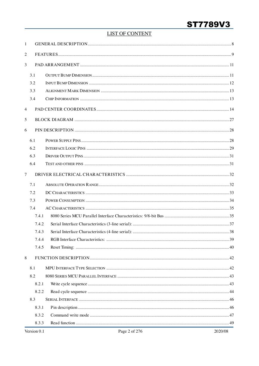
LIST OF CONTENT
1
2
3
4
5
6
GENERAL DESCRIPTION ................................................................................................................................... 8
FEATURES .............................................................................................................................................................. 9
PAD ARRANGEMENT ........................................................................................................................................ 11
3.1
3.2
3.3
3.4
OUTPUT BUMP DIMENSION ............................................................................................................................. 11
INPUT BUMP DIMENSION ................................................................................................................................ 12
ALIGNMENT MARK DIMENSION ..................................................................................................................... 13
CHIP INFORMATION ........................................................................................................................................ 13
PAD CENTER COORDINATES ......................................................................................................................... 14
BLOCK DIAGRAM ............................................................................................................................................. 27
PIN DESCRIPTION ............................................................................................................................................. 28
6.1
6.2
6.3
6.4
POWER SUPPLY PINS ....................................................................................................................................... 28
INTERFACE LOGIC PINS .................................................................................................................................. 29
DRIVER OUTPUT PINS ..................................................................................................................................... 31
TEST AND OTHER PINS .................................................................................................................................... 31
7
DRIVER ELECTRICAL CHARACTERISTICS .............................................................................................. 32
7.1
7.2
7.3
7.4
7.4.1
7.4.2
7.4.3
7.4.4
7.4.5
ABSOLUTE OPERATION RANGE ....................................................................................................................... 32
DC CHARACTERISTICS ................................................................................................................................... 33
POWER CONSUMPTION ................................................................................................................................... 34
AC CHARACTERISTICS ................................................................................................................................... 35
8080 Series MCU Parallel Interface Characteristics: 9/8-bit Bus ........................................................... 35
Serial Interface Characteristics (3-line serial): ........................................................................................ 37
Serial Interface Characteristics (4-line serial): ........................................................................................ 38
RGB Interface Characteristics: ................................................................................................................ 39
Reset Timing: ............................................................................................................................................ 40
8
FUNCTION DESCRIPTION ............................................................................................................................... 42
8.1
8.2
MPU INTERFACE TYPE SELECTION ................................................................................................................ 42
8080 SERIES MCU PARALLEL INTERFACE ...................................................................................................... 43
8.2.1 Write cycle sequence ................................................................................................................................. 43
8.2.2
Read cycle sequence ................................................................................................................................. 44
8.3
SERIAL INTERFACE ......................................................................................................................................... 46
8.3.1
Pin description .......................................................................................................................................... 46
8.3.2 Command write mode ............................................................................................................................... 47
Read function ............................................................................................................................................ 49
8.3.3
Version 0.1 Page 2 of 276 2020/08
�
ST7789V3
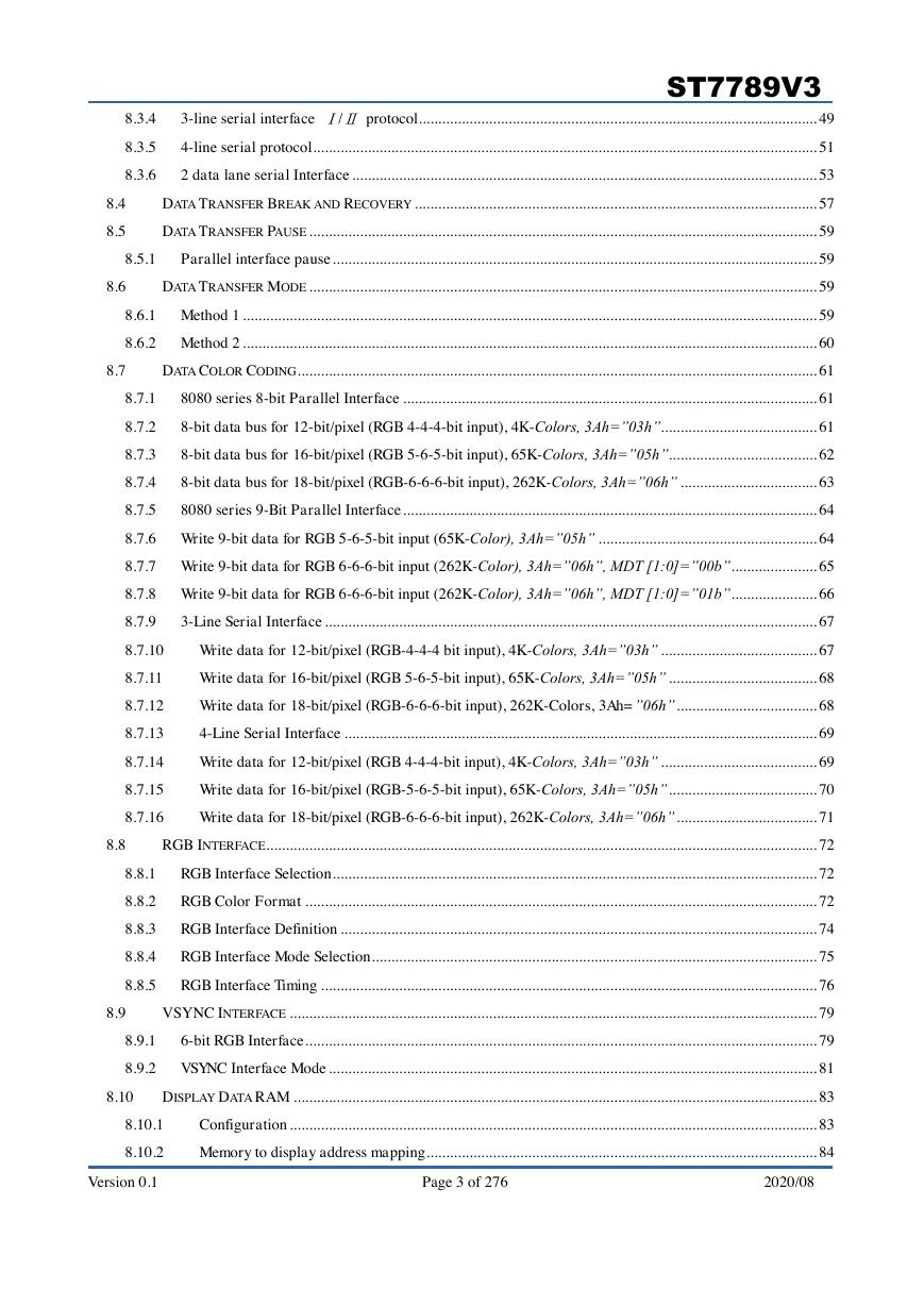
3-line serial interface Ⅰ/Ⅱ protocol ...................................................................................................... 49
4-line serial protocol ................................................................................................................................. 51
2 data lane serial Interface ....................................................................................................................... 53
DATA TRANSFER BREAK AND RECOVERY ....................................................................................................... 57
DATA TRANSFER PAUSE .................................................................................................................................. 59
8.3.4
8.3.5
8.3.6
8.4
8.5
8.5.1
Parallel interface pause ............................................................................................................................ 59
8.6
DATA TRANSFER MODE .................................................................................................................................. 59
8.6.1 Method 1 ................................................................................................................................................... 59
8.6.2 Method 2 ................................................................................................................................................... 60
8.7
DATA COLOR CODING ..................................................................................................................................... 61
8.7.1
8.7.2
8.7.3
8.7.4
8.7.5
8080 series 8-bit Parallel Interface .......................................................................................................... 61
8-bit data bus for 12-bit/pixel (RGB 4-4-4-bit input), 4K-Colors, 3Ah=”03h”........................................ 61
8-bit data bus for 16-bit/pixel (RGB 5-6-5-bit input), 65K-Colors, 3Ah=”05h”...................................... 62
8-bit data bus for 18-bit/pixel (RGB-6-6-6-bit input), 262K-Colors, 3Ah=”06h” ................................... 63
8080 series 9-Bit Parallel Interface .......................................................................................................... 64
8.7.6 Write 9-bit data for RGB 5-6-5-bit input (65K-Color), 3Ah=”05h” ........................................................ 64
8.7.7 Write 9-bit data for RGB 6-6-6-bit input (262K-Color), 3Ah=”06h”, MDT [1:0]=”00b” ...................... 65
8.7.8 Write 9-bit data for RGB 6-6-6-bit input (262K-Color), 3Ah=”06h”, MDT [1:0]=”01b” ...................... 66
8.7.9
3-Line Serial Interface .............................................................................................................................. 67
8.7.10
8.7.11
8.7.12
8.7.13
8.7.14
8.7.15
8.7.16
Write data for 12-bit/pixel (RGB-4-4-4 bit input), 4K-Colors, 3Ah=”03h” ........................................ 67
Write data for 16-bit/pixel (RGB 5-6-5-bit input), 65K-Colors, 3Ah=”05h” ...................................... 68
Write data for 18-bit/pixel (RGB-6-6-6-bit input), 262K-Colors, 3Ah=”06h” .................................... 68
4-Line Serial Interface ......................................................................................................................... 69
Write data for 12-bit/pixel (RGB 4-4-4-bit input), 4K-Colors, 3Ah=”03h” ........................................ 69
Write data for 16-bit/pixel (RGB-5-6-5-bit input), 65K-Colors, 3Ah=”05h” ...................................... 70
Write data for 18-bit/pixel (RGB-6-6-6-bit input), 262K-Colors, 3Ah=”06h” .................................... 71
8.8
RGB INTERFACE ............................................................................................................................................. 72
8.8.1
8.8.2
8.8.3
8.8.4
8.8.5
RGB Interface Selection ............................................................................................................................ 72
RGB Color Format ................................................................................................................................... 72
RGB Interface Definition .......................................................................................................................... 74
RGB Interface Mode Selection .................................................................................................................. 75
RGB Interface Timing ............................................................................................................................... 76
8.9
VSYNC INTERFACE ....................................................................................................................................... 79
6-bit RGB Interface ................................................................................................................................... 79
VSYNC Interface Mode ............................................................................................................................. 81
8.9.1
8.9.2
8.10
DISPLAY DATA RAM ...................................................................................................................................... 83
Configuration ....................................................................................................................................... 83
Memory to display address mapping .................................................................................................... 84
8.10.1
8.10.2
Version 0.1 Page 3 of 276 2020/08
�
ST7789V3
ADDRESS CONTROL ........................................................................................................................................ 85
NORMAL DISPLAY ON OR PARTIAL MODE ON, VERTICAL SCROLL OFF .......................................................... 87
VERTICAL SCROLL MODE ............................................................................................................................... 89
8.11
8.12
8.13
8.13.1
8.13.2
Rolling scroll ........................................................................................................................................ 89
Vertical Scroll Example ........................................................................................................................ 91
8.14
TEARING EFFECT ............................................................................................................................................ 93
8.14.1
8.14.2
8.14.3
8.14.4
Tearing effect line modes ...................................................................................................................... 93
Tearing effect line timings .................................................................................................................... 94
Example 1: MPU Write is faster than panel read................................................................................. 95
Example 2: MPU write is slower than panel read ............................................................................... 96
8.15
POWER ON/OFF SEQUENCE ........................................................................................................................... 97
8.15.1
Uncontrolled Power Off ....................................................................................................................... 98
8.16
POWER LEVEL DEFINITION ............................................................................................................................. 99
8.16.1
Power Level.......................................................................................................................................... 99
8.17
8.18
8.19
8.20
POWER FLOW CHART ................................................................................................................................... 100
GAMMA CORRECTION .................................................................................................................................. 101
GRAY VOLTAGE GENERATOR FOR DIGITAL GAMMA CORRECTION ................................................................... 106
DISPLAY DIMMING ....................................................................................................................................... 107
8.20.1
8.20.2
8.20.3
General Description ........................................................................................................................... 107
Dimming Requirement ........................................................................................................................ 107
Definition of brightness transition time.............................................................................................. 109
8.21
CONTENT ADAPTIVE BRIGHTNESS CONTROL (CABC) ................................................................................. 110
8.21.1
8.21.2
Definition of CABC ............................................................................................................................ 110
Minimum brightness setting of CABC function .................................................................................. 114
9
COMMAND ........................................................................................................................................................ 116
9.1
SYSTEM FUNCTION COMMAND TABLE 1 ....................................................................................................... 116
9.1.1 NOP (00h) ............................................................................................................................................... 121
9.1.2
9.1.3
9.1.4
9.1.5
9.1.6
9.1.7
9.1.8
SWRESET (01h): Software Reset ............................................................................................................ 122
RDDID (04h): Read Display ID ............................................................................................................. 124
RDDST (09h): Read Display Status ........................................................................................................ 126
RDDPM (0Ah): Read Display Power Mode ........................................................................................... 129
RDDMADCTL (0Bh): Read Display MADCTL ...................................................................................... 131
RDDCOLMOD (0Ch): Read Display Pixel Format ............................................................................... 133
RDDIM (0Dh): Read Display Image Mode ............................................................................................ 135
9.1.9
9.1.10
9.1.11
RDDSM (0Eh): Read Display Signal Mode ............................................................................................ 137
RDDSDR (0Fh): Read Display Self-Diagnostic Result ...................................................................... 139
SLPIN (10h): Sleep in ........................................................................................................................ 141
Version 0.1 Page 4 of 276 2020/08
�
ST7789V3
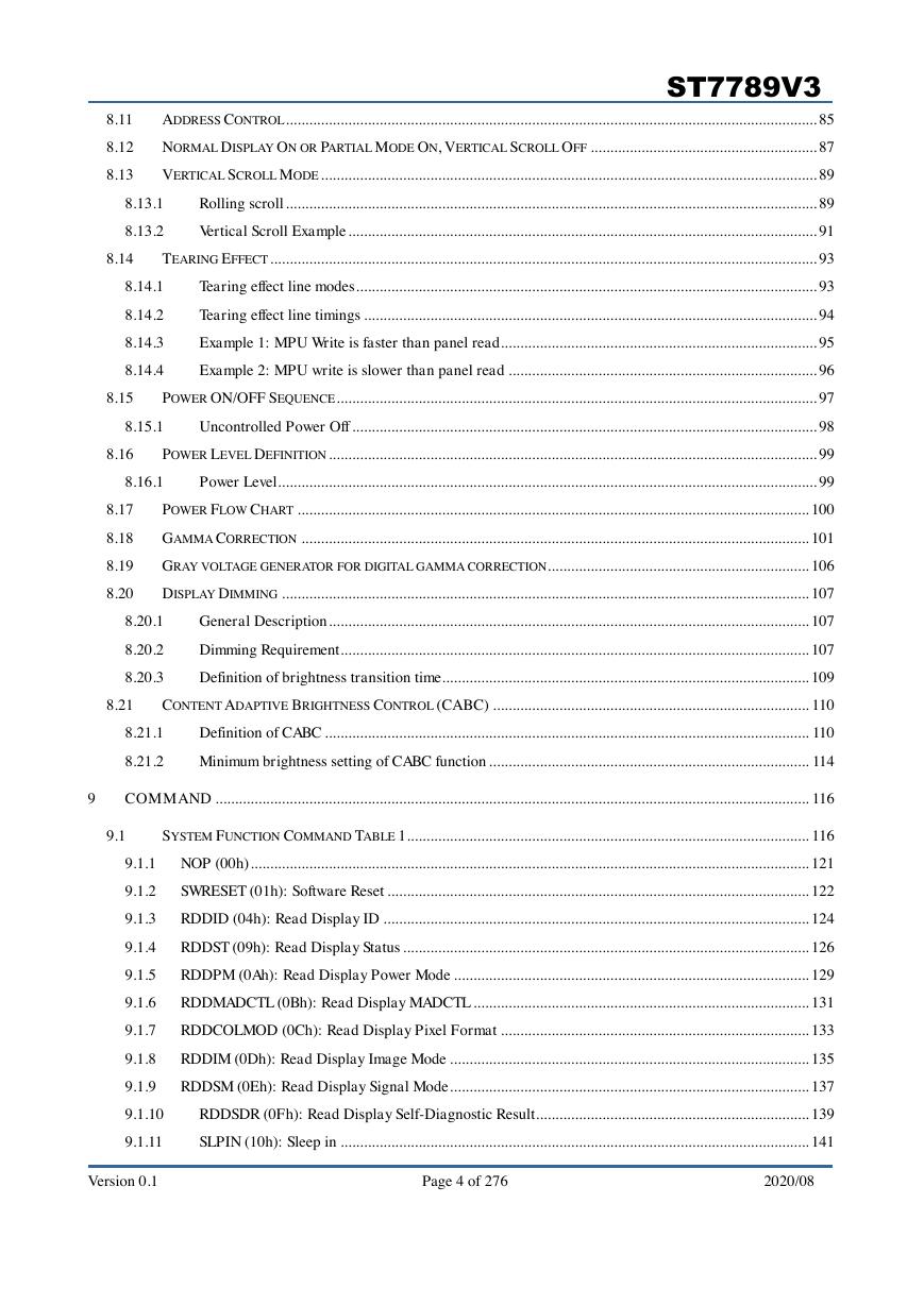
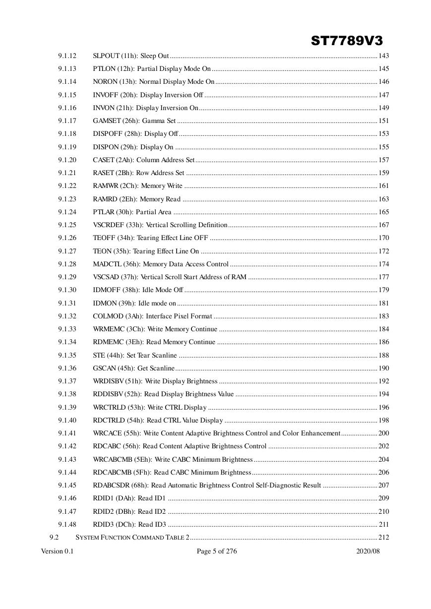
SLPOUT (11h): Sleep Out .................................................................................................................. 143
PTLON (12h): Partial Display Mode On ........................................................................................... 145
NORON (13h): Normal Display Mode On ......................................................................................... 146
INVOFF (20h): Display Inversion Off ............................................................................................... 147
INVON (21h): Display Inversion On .................................................................................................. 149
GAMSET (26h): Gamma Set .............................................................................................................. 151
DISPOFF (28h): Display Off ............................................................................................................. 153
DISPON (29h): Display On ............................................................................................................... 155
CASET (2Ah): Column Address Set .................................................................................................... 157
RASET (2Bh): Row Address Set ......................................................................................................... 159
RAMWR (2Ch): Memory Write .......................................................................................................... 161
RAMRD (2Eh): Memory Read ........................................................................................................... 163
PTLAR (30h): Partial Area ................................................................................................................ 165
VSCRDEF (33h): Vertical Scrolling Definition .................................................................................. 167
TEOFF (34h): Tearing Effect Line OFF ............................................................................................ 170
TEON (35h): Tearing Effect Line On ................................................................................................. 172
MADCTL (36h): Memory Data Access Control ................................................................................. 174
VSCSAD (37h): Vertical Scroll Start Address of RAM ....................................................................... 177
IDMOFF (38h): Idle Mode Off .......................................................................................................... 179
IDMON (39h): Idle mode on .............................................................................................................. 181
COLMOD (3Ah): Interface Pixel Format .......................................................................................... 183
WRMEMC (3Ch): Write Memory Continue ....................................................................................... 184
RDMEMC (3Eh): Read Memory Continue ........................................................................................ 186
STE (44h): Set Tear Scanline ............................................................................................................. 188
GSCAN (45h): Get Scanline ............................................................................................................... 190
WRDISBV (51h): Write Display Brightness ....................................................................................... 192
RDDISBV (52h): Read Display Brightness Value .............................................................................. 194
WRCTRLD (53h): Write CTRL Display ............................................................................................. 196
RDCTRLD (54h): Read CTRL Value Display .................................................................................... 198
WRCACE (55h): Write Content Adaptive Brightness Control and Color Enhancement .................... 200
RDCABC (56h): Read Content Adaptive Brightness Control ............................................................ 202
WRCABCMB (5Eh): Write CABC Minimum Brightness .................................................................... 204
RDCABCMB (5Fh): Read CABC Minimum Brightness..................................................................... 206
RDABCSDR (68h): Read Automatic Brightness Control Self-Diagnostic Result .............................. 207
RDID1 (DAh): Read ID1 ................................................................................................................... 209
9.1.12
9.1.13
9.1.14
9.1.15
9.1.16
9.1.17
9.1.18
9.1.19
9.1.20
9.1.21
9.1.22
9.1.23
9.1.24
9.1.25
9.1.26
9.1.27
9.1.28
9.1.29
9.1.30
9.1.31
9.1.32
9.1.33
9.1.34
9.1.35
9.1.36
9.1.37
9.1.38
9.1.39
9.1.40
9.1.41
9.1.42
9.1.43
9.1.44
9.1.45
9.1.46
9.1.47
9.1.48
RDID2 (DBh): Read ID2 ................................................................................................................... 210
RDID3 (DCh): Read ID3 ................................................................................................................... 211
SYSTEM FUNCTION COMMAND TABLE 2 ....................................................................................................... 212
9.2
Version 0.1 Page 5 of 276 2020/08
�
ST7789V3
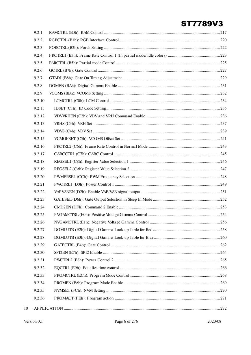
RAMCTRL (B0h): RAM Control ............................................................................................................. 217
RGBCTRL (B1h): RGB Interface Control............................................................................................... 220
PORCTRL (B2h): Porch Setting ............................................................................................................. 222
FRCTRL1 (B3h): Frame Rate Control 1 (In partial mode/ idle colors) ................................................. 223
PARCTRL (B5h): Partial mode Control .................................................................................................. 225
9.2.1
9.2.2
9.2.3
9.2.4
9.2.5
9.2.6 GCTRL (B7h): Gate Control ................................................................................................................... 227
9.2.7 GTADJ (B8h): Gate On Timing Adjustment ............................................................................................ 229
9.2.8 DGMEN (BAh): Digital Gamma Enable ................................................................................................ 231
9.2.9
VCOMS (BBh): VCOMS Setting ............................................................................................................. 232
9.2.10
9.2.11
9.2.12
9.2.13
9.2.14
9.2.15
9.2.16
9.2.17
9.2.18
9.2.19
9.2.20
9.2.21
9.2.22
9.2.23
9.2.24
9.2.25
9.2.26
9.2.27
9.2.28
9.2.29
9.2.30
9.2.31
9.2.32
9.2.33
9.2.34
9.2.35
9.2.36
LCMCTRL (C0h): LCM Control ........................................................................................................ 234
IDSET (C1h): ID Code Setting ........................................................................................................... 235
VDVVRHEN (C2h): VDV and VRH Command Enable ...................................................................... 236
VRHS (C3h): VRH Set ........................................................................................................................ 237
VDVS (C4h): VDV Set ........................................................................................................................ 239
VCMOFSET (C5h): VCOMS Offset Set ............................................................................................. 241
FRCTRL2 (C6h): Frame Rate Control in Normal Mode ................................................................... 243
CABCCTRL (C7h): CABC Control .................................................................................................... 245
REGSEL1 (C8h): Register Value Selection 1 ..................................................................................... 246
REGSEL2 (CAh): Register Value Selection 2 ..................................................................................... 247
PWMFRSEL (CCh): PWM Frequency Selection ............................................................................... 248
PWCTRL1 (D0h): Power Control 1 ................................................................................................... 249
VAPVANEN (D2h): Enable VAP/VAN signal output .......................................................................... 251
GATESEL (D6h): Gate Output Selection in Sleep In Mode ............................................................... 252
CMD2EN (DFh): Command 2 Enable ............................................................................................... 253
PVGAMCTRL (E0h): Positive Voltage Gamma Control .................................................................... 254
NVGAMCTRL (E1h): Negative Voltage Gamma Control .................................................................. 256
DGMLUTR (E2h): Digital Gamma Look-up Table for Red ............................................................... 258
DGMLUTB (E3h): Digital Gamma Look-up Table for Blue .............................................................. 260
GATECTRL (E4h): Gate Control ....................................................................................................... 262
SPI2EN (E7h): SPI2 Enable .............................................................................................................. 264
PWCTRL2 (E8h): Power Control 2 ................................................................................................... 265
EQCTRL (E9h): Equalize time control .............................................................................................. 266
PROMCTRL (ECh): Program Mode Control ..................................................................................... 268
PROMEN (FAh): Program Mode Enable ........................................................................................... 269
NVMSET (FCh): NVM Setting ........................................................................................................... 270
PROMACT (FEh): Program action ................................................................................................... 271
10 APPLICATION ................................................................................................................................................... 272
Version 0.1 Page 6 of 276 2020/08
�
ST7789V3
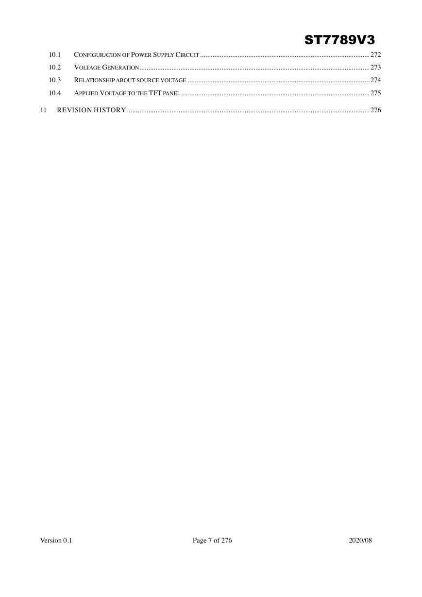
CONFIGURATION OF POWER SUPPLY CIRCUIT ............................................................................................... 272
VOLTAGE GENERATION................................................................................................................................. 273
RELATIONSHIP ABOUT SOURCE VOLTAGE ...................................................................................................... 274
APPLIED VOLTAGE TO THE TFT PANEL ......................................................................................................... 275
10.1
10.2
10.3
10.4
11 REVISION HISTORY ........................................................................................................................................ 276
Version 0.1 Page 7 of 276 2020/08
�
ST7789V3
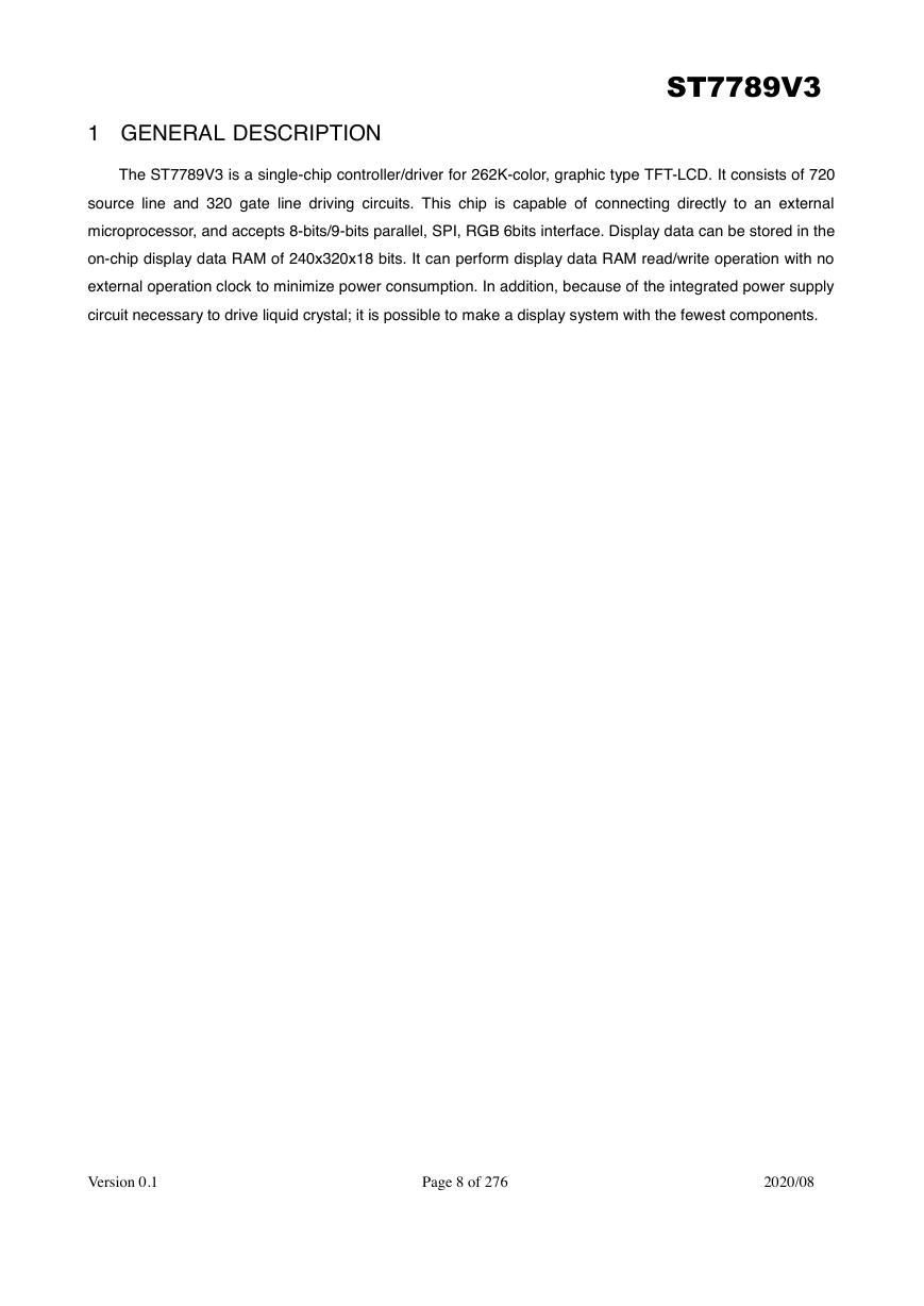
1 GENERAL DESCRIPTION
The ST7789V3 is a single-chip controller/driver for 262K-color, graphic type TFT-LCD. It consists of 720
source line and 320 gate line driving circuits. This chip is capable of connecting directly to an external
microprocessor, and accepts 8-bits/9-bits parallel, SPI, RGB 6bits interface. Display data can be stored in the
on-chip display data RAM of 240x320x18 bits. It can perform display data RAM read/write operation with no
external operation clock to minimize power consumption. In addition, because of the integrated power supply
circuit necessary to drive liquid crystal; it is possible to make a display system with the fewest components.
Version 0.1 Page 8 of 276 2020/08
�


 V2版本原理图(Capacitive-Fingerprint-Reader-Schematic_V2).pdf
 摄像头工作原理.doc
 VL53L0X简要说明(En.FLVL53L00216).pdf
 原理图(DVK720-Schematic).pdf
 原理图(Pico-Clock-Green-Schdoc).pdf
 原理图(RS485-CAN-HAT-B-schematic).pdf
 File:SIM7500_SIM7600_SIM7800 Series_SSL_Application Note_V2.00.pdf
 ADS1263(Ads1262).pdf
 原理图(Open429Z-D-Schematic).pdf
 用户手册(Capacitive_Fingerprint_Reader_User_Manual_CN).pdf
 CY7C68013A(英文版)(CY7C68013A).pdf
 TechnicalReference_Dem.pdf