TFT LCD MODULE
1.47 inch 172RGB*320DOTS
MODULE NUMBER:
REVISION: A
Customer:
From:
Page 1
�
RReevviisseedd HHiissttoorryy
Part Number
Revision
Revision Content
Revised on
Page 2
�
CCoonntteennttss
RReevviissiioonn HHiissttoorryy
CCoonntteennttss
11.. GGeenneerraall DDeessccrriippttiioonn
22.. MMeecchhaanniiccaall DDrraawwiinngg
33.. PPiinn DDeessccrriippttiioonn
44.. EElleeccttrriiccaall CChhaarraacctteerriissttiiccss
55.. OOppttiiccaall CChhaarraacctteerriissttiiccss
66.. RReelliiaabbiilliittyy
77.. PPaacckkaaggee SSppeecciiffiiccaattiioonnss
88.. IInnccoommiinngg IInnssppeeccttiioonn ssttaannddaarrddss
99.. PPrreeccaauuttiioonnss WWhheenn UUssiinngg TThheessee TTFFTT DDiissppllaayy MMoodduulleess
Page 3
�
11.. GGeenneerraall DDeessccrriippttiioonn
1.1 Description
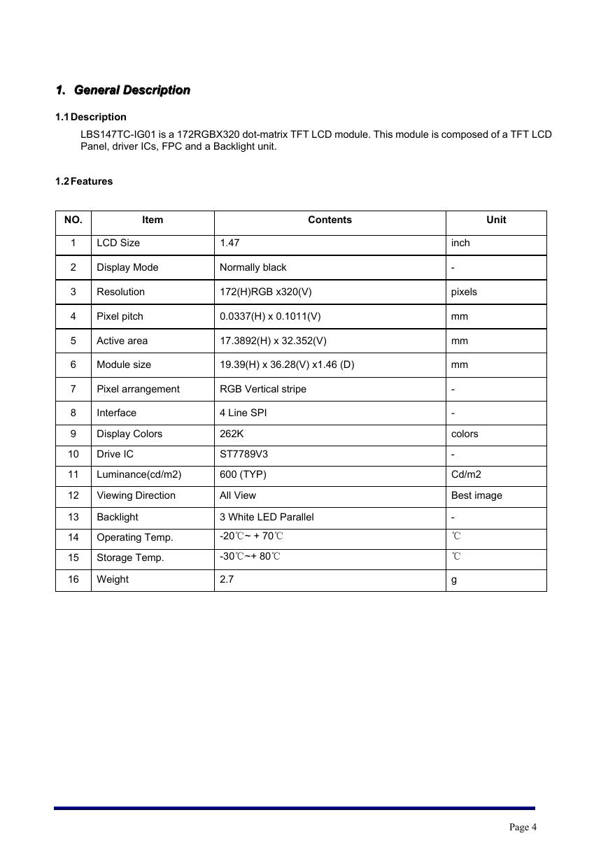
LBS147TC-IG01 is a 172RGBX320 dot-matrix TFT LCD module. This module is composed of a TFT LCD
Panel, driver ICs, FPC and a Backlight unit.
1.2 Features
NO.
Item
Contents
Unit
1
2
3
4
5
6
7
8
9
10
11
12
LCD Size
1.47
Display Mode
Normally black
Resolution
Pixel pitch
Active area
Module size
172(H)RGB x320(V)
0.0337(H) x 0.1011(V)
17.3892(H) x 32.352(V)
19.39(H) x 36.28(V) x1.46 (D)
Pixel arrangement
RGB Vertical stripe
Interface
Display Colors
Drive IC
Luminance(cd/m2)
Viewing Direction
4 Line SPI
262K
ST7789V3
600 (TYP)
All View
Backlight
13
14 Operating Temp.
15
Storage Temp.
3 White LED Parallel
-20℃~ + 70℃
-30℃~+ 80℃
16 Weight
2.7
inch
-
pixels
mm
mm
mm
-
-
colors
-
Cd/m2
Best image
-
℃
℃
g
Page 4
�
V
2
.
3
~
8
.
2
=
f
V
A
m
0
6
=
f
I
.
v
e
R
A
r
e
b
m
u
N
g
n
i
w
a
r
D
T
F
T
'
'
7
4
.
1
l
a
i
r
e
t
a
M
e
d
i
m
i
y
l
o
P
/
e
m
i
L
a
d
o
S
e
z
i
S
3
A
t
e
e
h
S
1
f
o
1
e
l
a
c
S
1
:
1
.
M
.
P
.
E
/
l
e
n
a
P
.
E
.
E
1
0
G
I
-
C
T
7
4
1
S
B
L
n
w
a
r
D
G
N
O
H
5
1
3
0
1
2
0
2
e
l
t
i
T
m
m
t
i
n
U
d
e
i
f
i
c
e
p
S
e
s
i
w
r
e
h
t
O
s
s
e
l
n
U
y
B
e
t
a
D
2
.
0
±
1
±
n
o
i
s
n
e
m
D
i
e
l
g
n
A
e
c
n
a
r
e
l
o
T
s
s
e
n
h
g
u
o
R
l
a
r
e
n
e
G
l
a
v
o
r
p
p
A
r
e
m
o
t
s
u
C
e
r
u
t
a
n
g
i
S
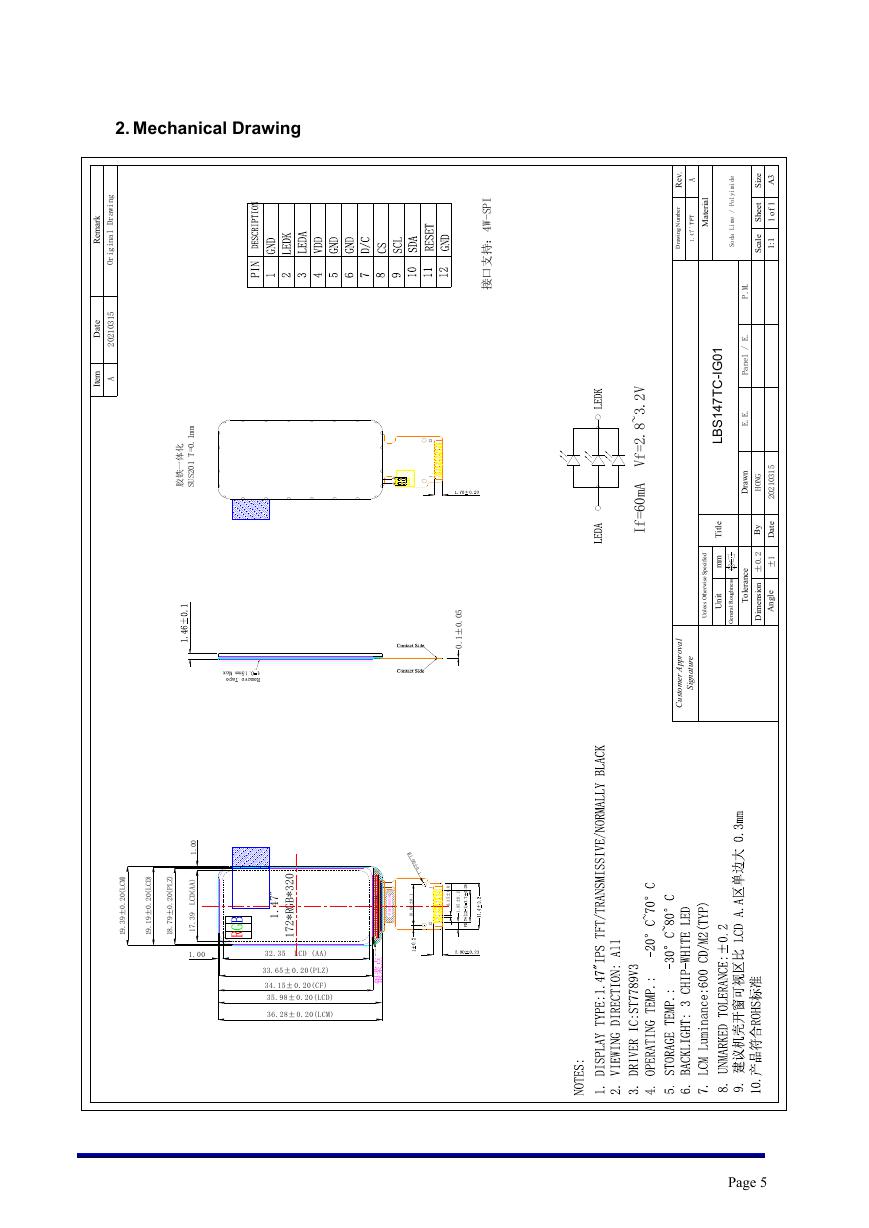
2. Mechanical Drawing
k
r
a
m
e
R
g
n
i
w
a
r
D
l
a
n
i
g
i
r
O
e
t
a
D
5
1
3
0
1
2
0
2
m
e
t
I
A
m
m
1
.
0
=
T
1
0
2
S
U
S
化
体
一
铁
胶
I
P
S
-
W
4
:
持
支
口
接
2
1
1
5
0
.
0
±
1
.
0
0
0
.
1
)
A
A
(
D
C
L
9
3
.
7
1
)
M
C
L
(
0
2
.
0
±
9
3
.
9
1
)
D
C
L
(
0
2
.
0
±
9
1
.
9
1
)
Z
L
P
(
0
2
.
0
±
9
7
.
8
1
0
2
3
*
B
G
R
*
2
7
1
"
7
4
.
1
1
.
0
0
±
0
.
1
域
区
折
弯
面
单
1
.
0
±
0
0
.
0
1
3
0
.
0
±
5
3
.
0
5
1
.
0
±
5
8
.
1
1
2
1
1.00
32.35 LCD (AA)
33.65± 0.20(PLZ)
34.15± 0.20(CF)
35.98± 0.20(LCD)
36.28± 0.20(LCM)
A
点
浆
银
Page 5
�
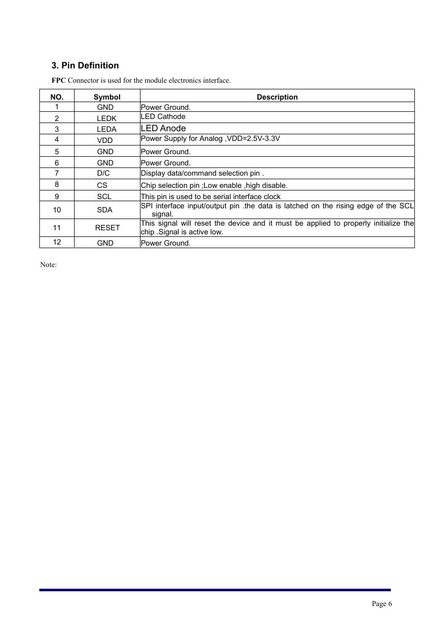
3. Pin Definition
FPC Connector is used for the module electronics interface.
Description
Symbol
GND
LEDK
LEDA
VDD
GND
GND
D/C
CS
SCL
SDA
RESET
GND
NO.
1
2
3
4
5
6
7
8
9
10
11
12
Note:
Power Ground.
LED Cathode
LED Anode
Power Supply for Analog ,VDD=2.5V-3.3V
Power Ground.
Power Ground.
Display data/command selection pin .
Chip selection pin ;Low enable ,high disable.
This pin is used to be serial interface clock
SPI interface input/output pin .the data is latched on the rising edge of the SCL
This signal will reset the device and it must be applied to properly initialize the
chip .Signal is active low.
Power Ground.
signal.
Page 6
�
4. Electrical Characteristics
4.1 Absolute Maximum Ratings
Parameter
Supply Voltage (I/O)
Analog Supply Voltage
Logic Input Voltage
Operation Temperature
Storage Temperature
Symbol
VDD
VDDIO
VIN
Top
Tst
Min
-0.3
-0.3
-0.3
-20
-30
MAX
4.6
4.6
VDDIO+0.5
70
80
Unit
V
V
V
℃
℃
4.2 Operating Conditions
Parameter
System Voltage
Interface Operation Voltage
Gate Driver High Voltage
Gate Driver Low Voltage
Operating Current for VDD
Sleep_In Mode VDD
Sleep_In Mode VDDIO
4.3 Backlight Unit
Parameter
Voltage for LED backlight
Current for LED backlight
Power Consumption
Brightness
LED Life time
Symbol
VDD
VDDIO
VGH
VGL
IDD
I dd
I ddio
Symbol
VLED
ILED
Pbl
Lbr
-
Min
2.5
1.65
12.2
-12.5
-
-
-
Min
2.8
-
-
550
20000
TYP
2.8
1.8
-
-
8
15
5
TYP
3.0
60
180
600
-
MAX
3.3
3.3
14.97
-7.16
10
30
10
MAX
3.2
90
288
-
-
Unit
V
V
V
V
mA
uA
uA
Unit
V
mA
mW
cd/m2
hr
Note:
1. Where ILED =60mA , VLED=3.0V , Pbl= ILED x VLED
2. Uniform measure condition:
a:Measure 9 point ,Measure location is show below:
b:Uniform=(Min brightness/Max brightness)x100%
c:Best Contrast.
2W/3
W/3
3
/
H
3
/
H
2
)
H
(
a
e
r
a
e
v
i
t
c
A
Active area(W)
3. The environmental conducted under ambient air flow ,at Ta=25±2oC,60%RH±5%
Notes
Notes
Notes
3 LED
1
2
3
Page 7
�
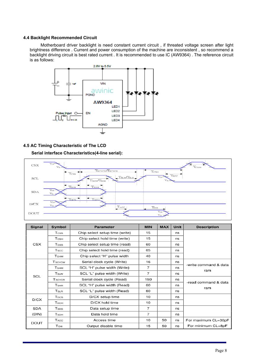
4.4 Backlight Recommended Circuit
Motherboard driver backlight is need constant current circuit , if threated voltage screen after light
brightness difference . Current and power consumption of the machine are inconsistent , so recommend a
backlight driving circuit is best rated current . It is recommended to use IC (AW9364) . The reference circuit
is as follows:
4.5 AC Timing Characteristic of The LCD
Serial interface Characteristics(4-line serial):
Page 8
�




 V2版本原理图(Capacitive-Fingerprint-Reader-Schematic_V2).pdf
 摄像头工作原理.doc
 VL53L0X简要说明(En.FLVL53L00216).pdf
 原理图(DVK720-Schematic).pdf
 原理图(Pico-Clock-Green-Schdoc).pdf
 原理图(RS485-CAN-HAT-B-schematic).pdf
 File:SIM7500_SIM7600_SIM7800 Series_SSL_Application Note_V2.00.pdf
 ADS1263(Ads1262).pdf
 原理图(Open429Z-D-Schematic).pdf
 用户手册(Capacitive_Fingerprint_Reader_User_Manual_CN).pdf
 CY7C68013A(英文版)(CY7C68013A).pdf
 TechnicalReference_Dem.pdf