XL-0807RGBC-WS2812B
Technical Data Sheet
0807炫彩 贴片式发光二极管
characteristic
* 外观尺寸(L/W/H):2.0*1.8*0.8mm
Appearance dimension (L / w / h): 2.0 x 1. 8 x 0.8 mm
* 发光颜色及胶体: 炫彩RGB/透明胶体
Luminous color and colloid: Colorful RGB/ transparent colloid
* 环保产品,符合ROHS要求
Environmental protection products meet ROHS requirements
* EIA规范标准包装
EIA standard packaging
* 适用于自动贴片机
Suitable for automatic mounter
* 适用于回流焊制程
Suitable for reflow soldering process
product application
* LED全 彩 发 光 字 灯 串 , L E D 全 彩 模 组
Led full-color luminous word lamp string, led full-color module
* LED幻彩软硬灯条,LED护栏管
Led magic color soft and hard light strip, LED guardrail tube
* LED外 观 , 情 景 照 明
Led appearance, scene lighting
* LED异性屏
Led heterosexual screen
* 各种电子产品,电器设备跑马灯
All kinds of electronic products, electrical equipment, runninglights
1
�
本产品是一款单线传输三通道(RGB)驱动控制电路与发光电路于一体的智能外控LED光源。产品内含有信号解码
模块、数据缓存器、内置恒流电路及RC振荡器;内部集成电流增益控制模块,CMOS制程,低压、低耗电;三通道
恒流驱动器默认输出19mA, 采用单线输出方式,串接各晶片之输出动作同步;上电默认不亮灯。数据协议采用单
极性归零码的通讯方式,单线传输LED驱动控制专用芯片,同时芯片内置的电流增益调节功能,可设置电流
1.75mA~19mA,共16个电流增益等级;PWM信号刷新率高达4KHz,显示更趋细腻平滑,解决拍摄画面暗条纹问题。
This product is an intelligent external control LED light source integrating single line transmission three channel (RGB)
drive control circuit and light-emitting circuit. RC signal decoding module, built-in buffer circuit and internal data storage
module; Internal integrated current gain control module, CMOS process, low voltage and low power consumption; The
default output of the three channel constant current driver is 19ma. The single line output mode is adopted, and the output
action of each chip in series is synchronous; The light is not on by default when powered on. The data protocol adopts the
communication mode of unipolar return to zero code, and the special chip for LED drive and control is transmitted in a
single line. At the same time, the built-in current gain adjustment function of the chip can set the current of 1.75ma ~ 19ma,
a total of 16 current gain levels; The refresh rate of PWM signal is up to 4kHz, the display is more delicate and smooth, and
the problem of dark stripes in the shooting picture is solved.
2
�
Catalogue
Electrical Characteristics............................................................................................................................. 4
Typical application Circuit......................................................................................................................7
Reliability Test Items And Conditions........................................................................................................8
Outline Dimensions.......................................................................................................................................9
Packaging......................................................................................................................................................10
Guideline for Soldering.............................................................................................................................. 12
Precautions....................................................................................................................................................14
3
�
Electrical Characteristics
(温度=25℃)
参数名称
Parameter
符号
Symbol
范围
Range
电压Voltage
逻辑输入电压
Logic input voltage
工作温度
Working temperature
储存温度
Storage temperature
OUT R/G/B端口耐压
Out R / G / B port
withstand voltage
ESD耐压ESD
Withstand voltage
VDD
VIN
Topt
Tstg
BVout
VESD
3.5~+5.5
-0.4~VDD+0.4
-40~+150
-55~+150
16
>2K
Switching characteristics (VCC=5V,Ta=25℃):
单位
Unit
V
V
℃
℃
V
V
符号
Symbol
FPWM
参数
Parameter
OUT R/G/B输出
PWM频率
Out R / G / B output
PWM frequency
TPLH
TPHL
TTLH
TTHL
Tr
Tf
信号传输延时
Signal transmission delay
DOUT转换时间
Dout conversion time
OUT R/G/B转换时间
Out R / G / B conversion time
测试条件
Test conditions
最小值
Min
规格值
Typ.
最大值
Max.
单位
Units
IOUT=19mA,OUT端口
串联200Ω电阻至VDD
IOUT=19mA,the out
port is connected in series
with 200 Ω resistance to
VDD
DOUT端口对地负载电容
30pF,DIN至DOUT的信号
传输延时
Dout port ground load
capacitance 30pF, signal
transmission delay from
DIN to dout
DOUT端口对地负载电容
30pF
Dout port ground load
capacitance 30pF
IOUTR/B=19mA,OUTR/G
/B端口串联200Ω至VDD,
对地负载电容15pF
IOUTR/B=5mA , OUT R
/ G/ B port 200 Ω in series
to VDD, load capacitance
to ground 15pF
-
-
-
-
-
-
-
4.0
65
55
3.0
3.0
55
60
-
-
-
-
-
-
-
KHz
ns
ns
ns
ns
ns
ns
4
�
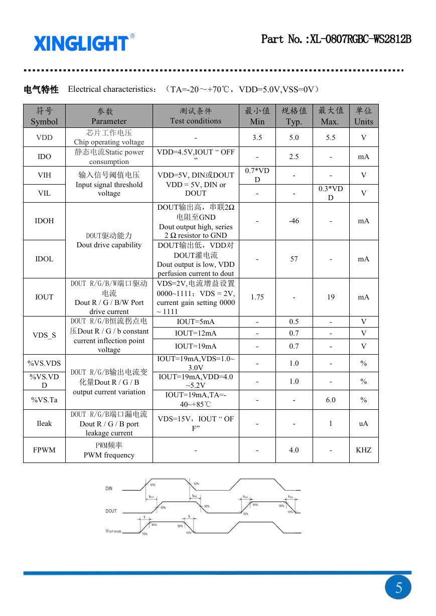
Electrical characteristics:(TA=-20~+70℃,VDD=5.0V,VSS=0V)
符号
Symbol
VDD
IDO
VIH
VIL
IDOH
IDOL
IOUT
VDS_S
%VS.VDS
%VS.VD
D
%VS.Ta
Ileak
FPWM
参数
Parameter
芯片工作电压
Chip operating voltage
静态电流Static power
consumption
输入信号阈值电压
Input signal threshold
voltage
DOUT驱动能力
Dout drive capability
DOUT R/G/B/W端口驱动
电流
Dout R / G / B/W Port
drive current
DOUT R/G/B恒流拐点电
压Dout R / G / b constant
current inflection point
voltage
DOUT R/G/B输出电流变
化量Dout R / G / B
output current variation
DOUT R/G/B端口漏电流
Dout R / G / B port
leakage current
PWM频率
PWM frequency
测试条件
Test conditions
-
VDD=4.5V,IOUT “ OFF
”
VDD=5V, DIN或DOUT
VDD = 5V, DIN or
DOUT
DOUT输出高,串联2Ω
电阻至GND
Dout output high, series
2 Ω resistor to GND
DOUT输出低,VDD对
DOUT灌电流
Dout output is low, VDD
perfusion current to dout
VDS=2V,电流增益设置
0000~1111;VDS = 2V,
current gain setting 0000
~ 1111
IOUT=5mA
IOUT=12mA
IOUT=19mA
IOUT=19mA,VDS=1.0~
IOUT=19mA,VDD=4.0
3.0V
~5.2V
IOUT=19mA,TA=-
40~+85℃
VDS=15V,IOUT “ OF
F”
-
最小值
Min
3.5
-
0.7*VD
D
-
-
-
1.75
-
-
-
-
-
-
-
-
2.5
-
-
-46
57
-
0.5
0.7
0.7
1.0
1.0
-
-
4.0
规格值
Typ.
5.0
最大值
Max.
5.5
单位
Units
V
mA
V
V
mA
mA
-
-
0.3*VD
D
-
-
19
mA
-
-
-
-
-
6.0
1
-
V
V
V
%
%
%
uA
KHZ
5
�
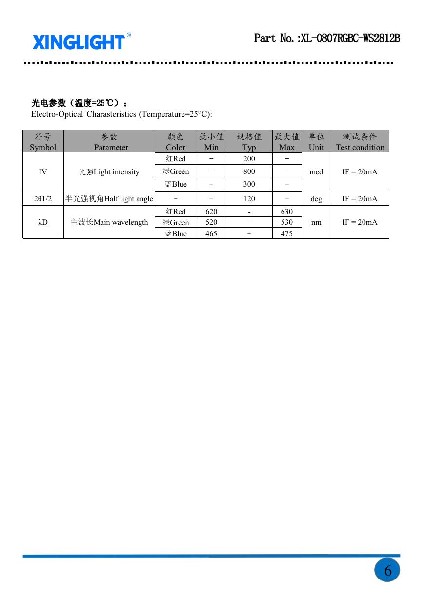
Electro-Optical Charasteristics (Temperature=25°C):
符号
Symbol
参数
Parameter
IV
光强Light intensity
颜色
Color
红Red
绿Green
蓝Blue
2θ1/2 半光强视角Half light angle
-
λD
主波长Main wavelength
红Red
绿Green
蓝Blue
最小值
规格值
Min
-
-
-
-
620
520
465
Typ
200
800
300
120
-
-
-
最大值
Max
单位
Unit
测试条件
Test condition
-
-
-
-
630
530
475
mcd
IF = 20mA
deg
nm
IF = 20mA
IF = 20mA
6
�
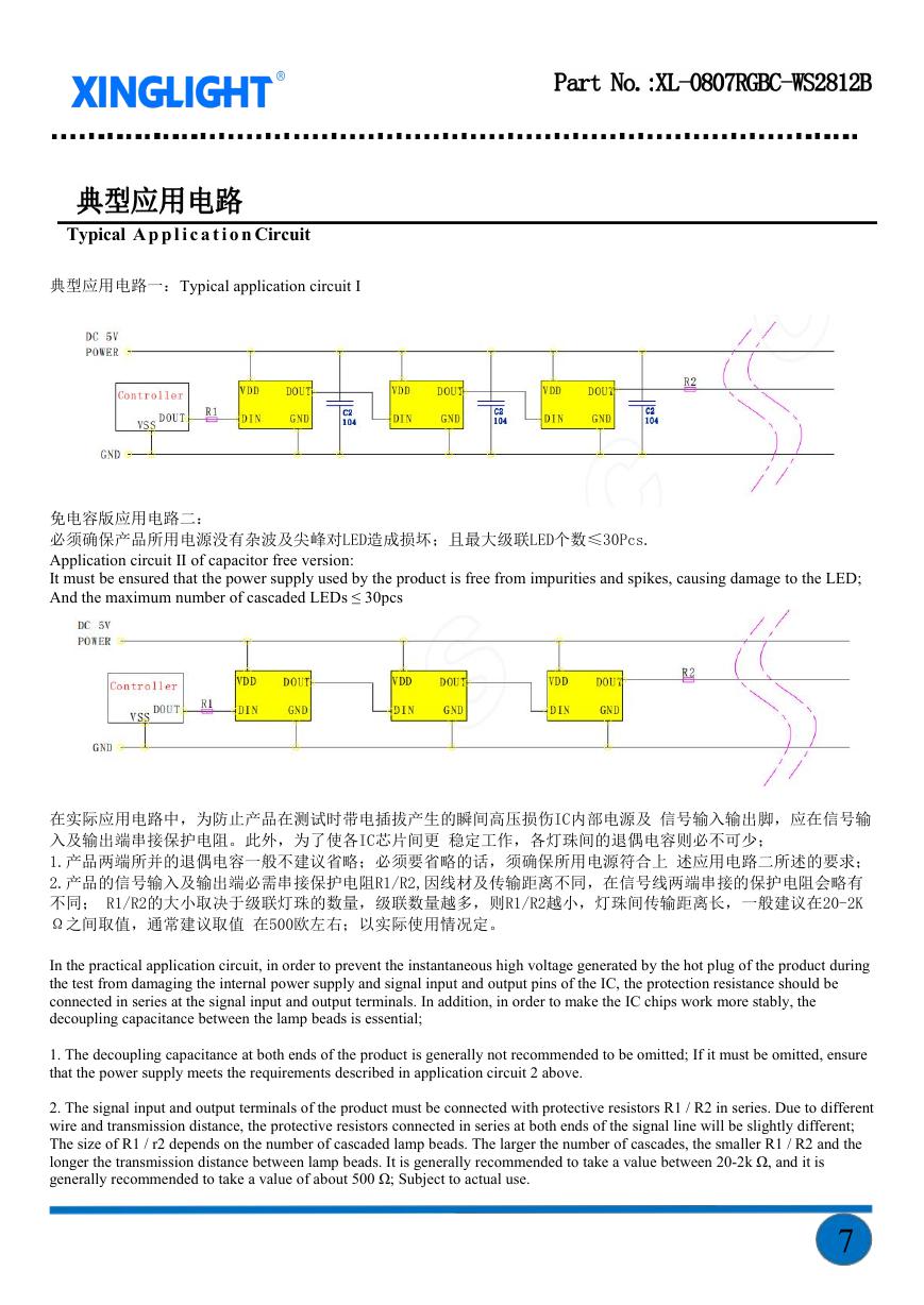
Typical Ap p l i c a t io n Circuit
典型应用电路一:Typical application circuit I
免电容版应用电路二:
必须确保产品所用电源没有杂波及尖峰对LED造成损坏;且最大级联LED个数≤30Pcs.
Application circuit II of capacitor free version:
It must be ensured that the power supply used by the product is free from impurities and spikes, causing damage to the LED;
And the maximum number of cascaded LEDs ≤ 30pcs
在实际应用电路中,为防止产品在测试时带电插拔产生的瞬间高压损伤IC内部电源及 信号输入输出脚,应在信号输
入及输出端串接保护电阻。此外,为了使各IC芯片间更 稳定工作,各灯珠间的退偶电容则必不可少;
1.产品两端所并的退偶电容一般不建议省略;必须要省略的话,须确保所用电源符合上 述应用电路二所述的要求;
2.产品的信号输入及输出端必需串接保护电阻R1/R2,因线材及传输距离不同,在信号线两端串接的保护电阻会略有
不同; R1/R2的大小取决于级联灯珠的数量,级联数量越多,则R1/R2越小,灯珠间传输距离长,一般建议在20-2K
Ω之间取值,通常建议取值 在500欧左右;以实际使用情况定。
In the practical application circuit, in order to prevent the instantaneous high voltage generated by the hot plug of the product during
the test from damaging the internal power supply and signal input and output pins of the IC, the protection resistance should be
connected in series at the signal input and output terminals. In addition, in order to make the IC chips work more stably, the
decoupling capacitance between the lamp beads is essential;
1. The decoupling capacitance at both ends of the product is generally not recommended to be omitted; If it must be omitted, ensure
that the power supply meets the requirements described in application circuit 2 above.
2. The signal input and output terminals of the product must be connected with protective resistors R1 / R2 in series. Due to different
wire and transmission distance, the protective resistors connected in series at both ends of the signal line will be slightly different;
The size of R1 / r2 depends on the number of cascaded lamp beads. The larger the number of cascades, the smaller R1 / R2 and the
longer the transmission distance between lamp beads. It is generally recommended to take a value between 20-2k Ω, and it is
generally recommended to take a value of about 500 Ω; Subject to actual use.
7
�
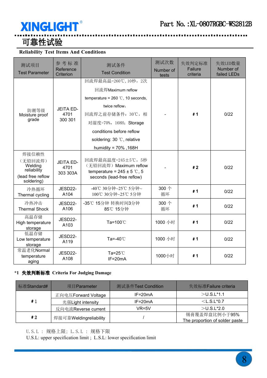
Reliability Test Items And Conditions
测试项目
Test Parameter
参 考 标 准
Reference
Criterion
测试条件
Test Condition
测试次数
Number of
tests
失效判定标准
Failure
criteria
失效LED数量
Number of
failed LEDs
回流焊最高温=260℃,10秒,2次
回流焊Maximum reflow
temperature = 260 ℃, 10 seconds,
twice reflow;
回流焊之前存储条件:30℃,相
对湿度=70%,168H;Storage
conditions before reflow
soldering: 30 ℃, relative
humidity = 70% ,168H
回流焊最高温度=245±5℃,5秒
(无铅回流焊)Maximum reflow
temperature = 245 ± 5 ℃, 5
seconds (lead-free reflow)
-
-
-40℃ 30分钟~25℃ 5分钟~
100℃ 30分钟~25℃ 5分钟
-35℃ 15分钟 转换时间3分钟
85℃ 15分钟
300 个
循环
300 个
循环
Ta=100℃
1000 小时
Ta=-40℃
Ta=25℃
IF=20mA
1000 小时
1000小时
﹟1
0/22
﹟2
﹟1
﹟1
﹟1
﹟1
﹟1
0/22
0/22
0/22
0/22
0/22
0/22
JEITA ED-
4701
300 301
JEITA ED-
4701
303 303A
JESD22-
A104
JESD22-
A106
JESD22-
A103
JESD22-
A119
JESD22-
A108
防潮等级
Moisture proof
grade
焊接信赖性
(无铅回流焊)
Welding
reliability
(lead free reflow
soldering)
冷热循环
Thermal cycling
冷热冲击
Thermal Shock
高温存储
High temperature
storage
低温存储
Low temperature
aging
storage
常温老化Normal
temperature
*1
Criteria For Judging Damage
标准Standard#
项目Parameter
测试条件Test Condition
失效标准Failure criteria
﹟1
﹟2
正向电压Forward Voltage
光强Light intensity
反向电流Reverse current
焊接可靠Weldingreliability
IF=20mA
IF=20mA
VR=5V
/
U.S.L : 规格上限; L.S.L : 规格下限
U.S.L: upper specification limit ; L.S.L: lower specification limit
>U.S.L*1.1
<L.S.L*0.7
>U.S.L*2.0
锡膏覆盖焊盘比例小于95%
The proportion of solder paste
8
�


 V2版本原理图(Capacitive-Fingerprint-Reader-Schematic_V2).pdf
 摄像头工作原理.doc
 VL53L0X简要说明(En.FLVL53L00216).pdf
 原理图(DVK720-Schematic).pdf
 原理图(Pico-Clock-Green-Schdoc).pdf
 原理图(RS485-CAN-HAT-B-schematic).pdf
 File:SIM7500_SIM7600_SIM7800 Series_SSL_Application Note_V2.00.pdf
 ADS1263(Ads1262).pdf
 原理图(Open429Z-D-Schematic).pdf
 用户手册(Capacitive_Fingerprint_Reader_User_Manual_CN).pdf
 CY7C68013A(英文版)(CY7C68013A).pdf
 TechnicalReference_Dem.pdf