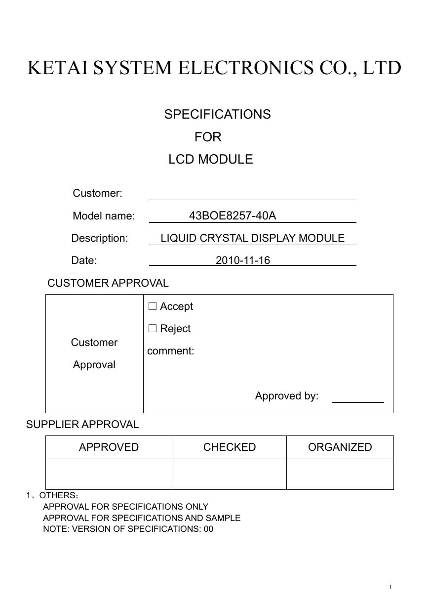
K ETAI SYSTEM ELECTRONICS CO., LTD
SPECIFICATIONS
FOR
LCD MODULE
Customer:
Model name: 43BOE8257-40A
Description: LIQUID CRYSTAL DISPLAY MODULE
Date: 2010-11-16
CUSTOMER APPROVAL
□ Accept
□ Reject
comment:
Customer
Approval
Approved by:
SUPPLIER APPROVAL
APPROVED
CHECKED
ORGANIZED
1、OTHERS:
APPROVAL FOR SPECIFICATIONS ONLY
APPROVAL FOR SPECIFICATIONS AND SAMPLE
NOTE: VERSION OF SPECIFICATIONS: 00
1
�
2、 OTHERS:
History of revision
Revision
00
Contents
New Revision
Date
2010-11-16
Note
1.0
2
�
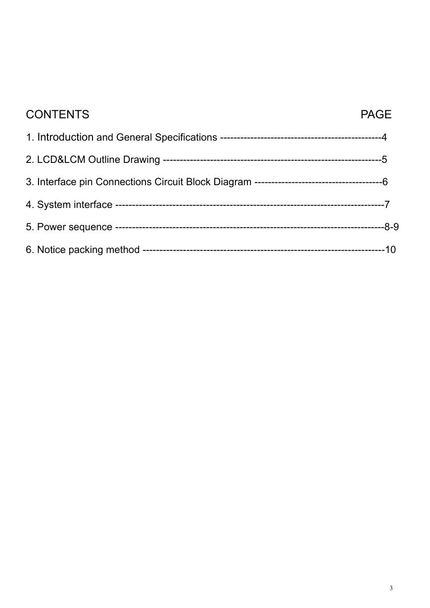
CONTENTS PAGE
1. Introduction and General Specifications ------------------------------------------------4
2. LCD&LCM Outline Drawing -----------------------------------------------------------------5
3. Interface pin Connections Circuit Block Diagram --------------------------------------6
4. System interface --------------------------------------------------------------------------------7
5. Power sequence --------------------------------------------------------------------------------8-9
6. Notice packing method ------------------------------------------------------------------------10
3
�
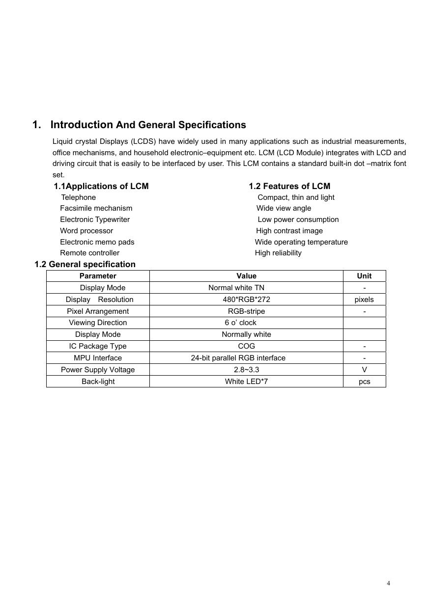
1. Introduction And General Specifications
Liquid crystal Displays (LCDS) have widely used in many applications such as industrial measurements,
office mechanisms, and household electronic–equipment etc. LCM (LCD Module) integrates with LCD and
driving circuit that is easily to be interfaced by user. This LCM contains a standard built-in dot –matrix font
set.
1.1Applications of LCM 1.2 Features of LCM
Telephone Compact, thin and light
Facsimile mechanism Wide view angle
Electronic Typewriter Low power consumption
Word processor High contrast image
Electronic memo pads Wide operating temperature
Remote controller High reliability
1.2 General specification
Parameter
Display Mode
Display Resolution
Pixel Arrangement
Viewing Direction
Display Mode
IC Package Type
MPU Interface
Power Supply Voltage
Back-light
Value
Normal white TN
480*RGB*272
RGB-stripe
6 o’ clock
Normally white
COG
24-bit parallel RGB interface
2.8~3.3
White LED*7
Unit
-
pixels
-
-
-
V
pcs
4
�
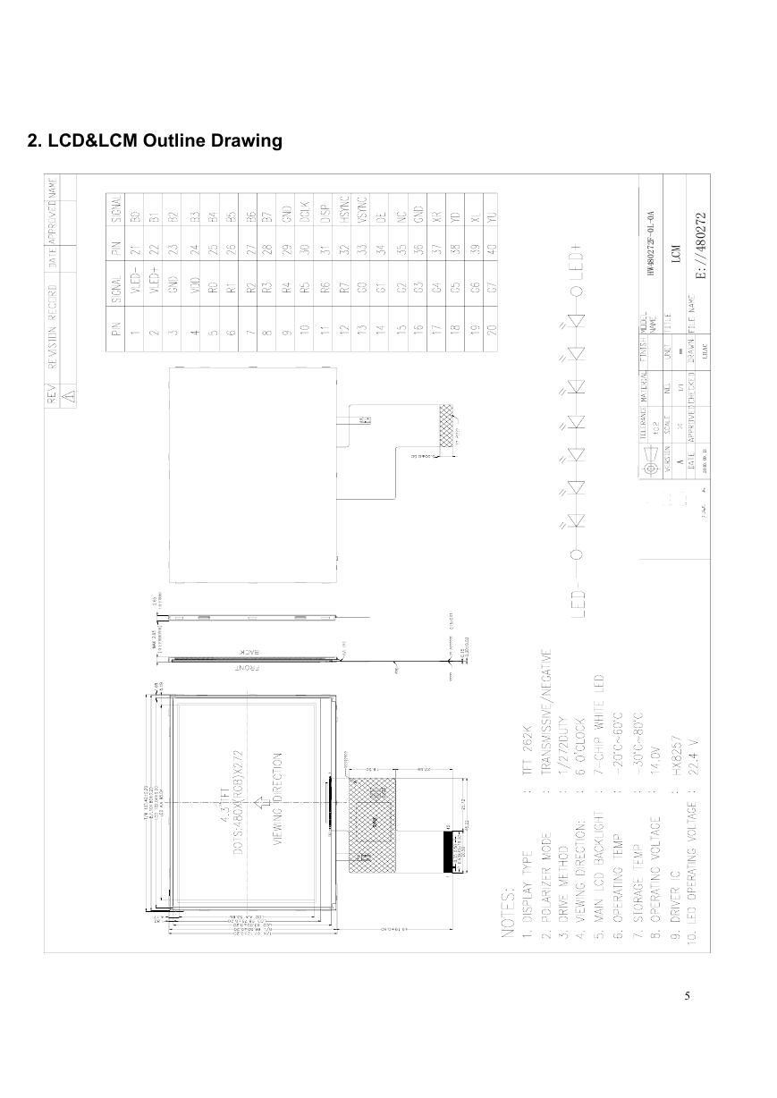
2. LCD&LCM Outline Drawing
)
框
铁
下
含
(
度
厚
框
铁
下
上
含
A
0
-
L
0
-
F
2
7
2
0
8
4
W
H
2
7
2
0
8
4
/
/
:
E
M
C
L
m
m
1
/
1
A
C
A
L
I
L
3
1
.
9
0
.
0
1
0
2
5
�
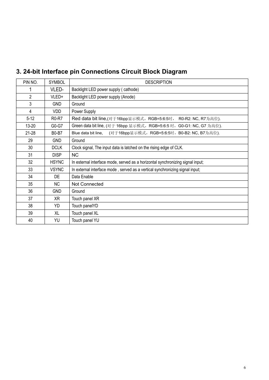
3. 24-bit Interface pin Connections Circuit Block Diagram
PIN NO.
1
2
3
4
5-12
13-20
21-28
29
30
31
32
33
34
35
36
37
38
39
40
SYMBOL
VLED-
VLED+
GND
VDD
R0-R7
G0-G7
B0-B7
GND
DCLK
DISP
HSYNC
VSYNC
DE
NC
GND
XR
YD
XL
YU
DESCRIPTION
Backlight LED power supply ( cathode)
Backlight LED power supply (Anode)
Ground
Power Supply
Red data bit line,(对于16bpp显示模式,RGB=5:6:5时, R0-R2: NC, R7为高位).
Green data bit line, (对于 16bpp 显示模式,RGB=5:6:5 时,G0-G1: NC, G7 为高位).
Blue data bit line, (对于16bpp显示模式,RGB=5:6:5时,B0-B2: NC, B7为高位).
Ground
Clock signal, The input data is latched on the rising edge of CLK.
NC
In esternal interface mode, served as a horizontal synchronizing signal input;
In external interface mode , served as a vertical synchronizing signal input;
Data Enable
Not Connected
Ground
Touch panel XR
Touch panelYD
Touch panel XL
Touch panel YU
6
�
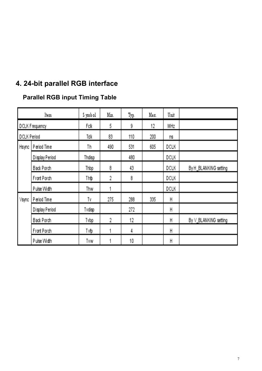
4. 24-bit parallel RGB interface
Parallel RGB input Timing Table
7
�
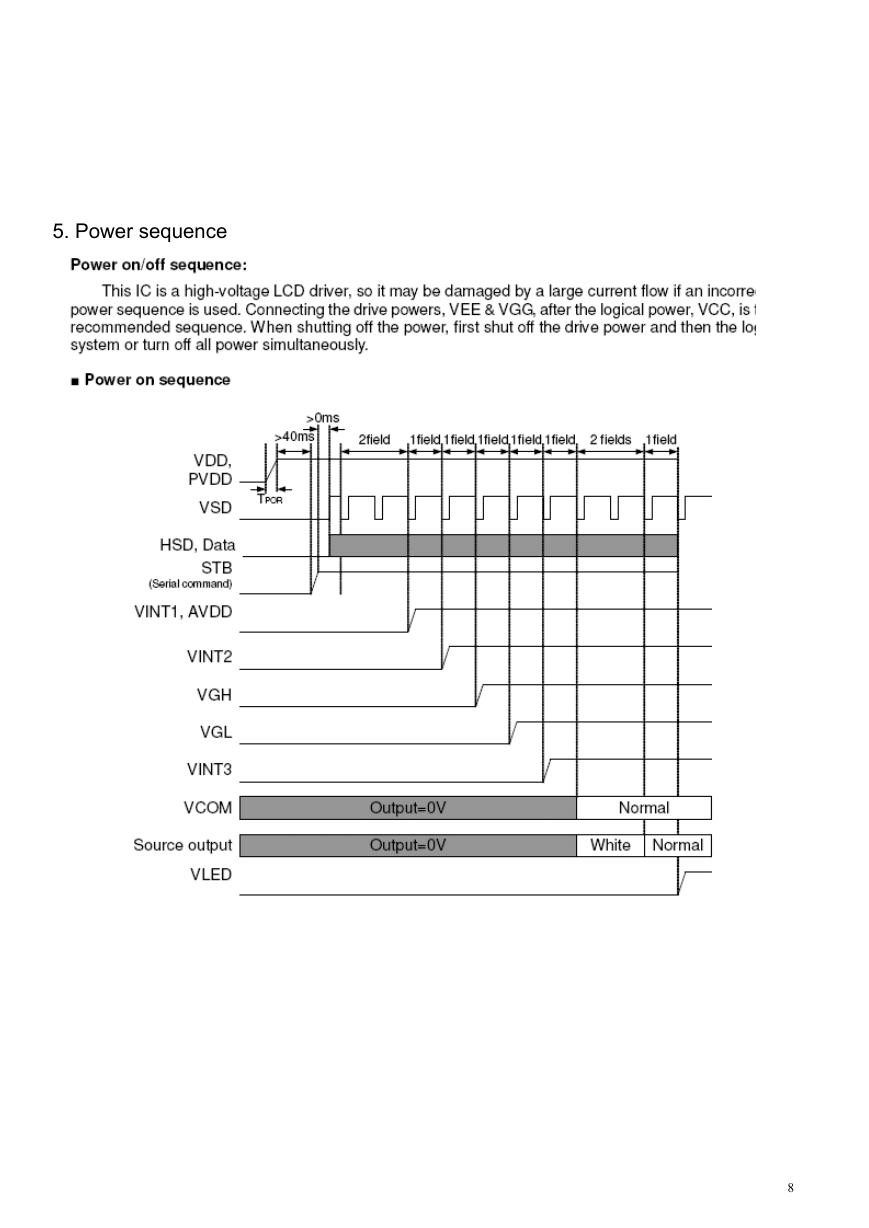
5. Power sequence
8
�


 V2版本原理图(Capacitive-Fingerprint-Reader-Schematic_V2).pdf
 摄像头工作原理.doc
 VL53L0X简要说明(En.FLVL53L00216).pdf
 原理图(DVK720-Schematic).pdf
 原理图(Pico-Clock-Green-Schdoc).pdf
 原理图(RS485-CAN-HAT-B-schematic).pdf
 File:SIM7500_SIM7600_SIM7800 Series_SSL_Application Note_V2.00.pdf
 ADS1263(Ads1262).pdf
 原理图(Open429Z-D-Schematic).pdf
 用户手册(Capacitive_Fingerprint_Reader_User_Manual_CN).pdf
 CY7C68013A(英文版)(CY7C68013A).pdf
 TechnicalReference_Dem.pdf