( DOC No. HX8257-A-DS )
480X272 TFT LCD Single Chip
Digital Driver
Version 01, July 2008
�
� Source Output �
� Gate Output �
July 2008
480X272 TFT LCD Single Chip
Digital Driver
1. General Description ................................................................................................................................... 4
2. Features....................................................................................................................................................... 5
3. Block Diagram ............................................................................................................................................ 6
4. Pad Assignment.......................................................................................................................................... 7
5. Pad Coordinates ......................................................................................................................................... 9
6. Pin Description ......................................................................................................................................... 25
7. Function Description................................................................................................................................ 28
7.1 Power relationship........................................................................................................................ 28
7.2 VCOM block................................................................................................................................... 29
7.3 Gate driver..................................................................................................................................... 30
7.4 Source driver................................................................................................................................. 32
7.5 Gamma adjustment ...................................................................................................................... 33
7.5.1 Structure of grayscale amplifier ........................................................................................... 34
7.5.2 Gamma adjustment register ................................................................................................ 36
7.5.2.1 Gradient adjusting register ........................................................................................ 36
7.5.2.2 Amplitude adjusting register...................................................................................... 36
7.5.2.3 Micro adjusting register ............................................................................................. 36
7.5.3 Ladder resistor / 8 to 1 selector........................................................................................... 37
7.6 PWM ............................................................................................................................................... 41
7.7 TCON.............................................................................................................................................. 42
7.7.1 LR/UD function .................................................................................................................... 43
7.7.2 Aging mode ......................................................................................................................... 43
7.7.3 TCON power on/off control.................................................................................................. 43
8. SPI Register............................................................................................................................................... 45
9. OTP Programming.................................................................................................................................... 58
10. DC Characteristics ................................................................................................................................... 60
11. AC Characteristics ................................................................................................................................... 62
11.1 Timing relationship among DE �
� VCOM................................ 62
11.2 Parallel RGB input timing requirement ...................................................................................... 62
11.3 Serial RGB input timing requirement ......................................................................................... 65
11.4 Input setup timing requirement................................................................................................... 67
12. Application Circuit.................................................................................................................................... 68
13. Ordering Information................................................................................................................................ 69
14. Revision History ....................................................................................................................................... 69
Himax Confidential
This information contained herein is the exclusive property of Himax and shell not be distributed, reproduced, or disclosed
in whole or in part without prior written permission of Himax.
-P.1-
July, 2008
�
�
�
�
�
�
�
480X272 TFT LCD Single Chip
Digital Driver
July 2008
Figure 3.1 Block Diagram .............................................................................................................. 6
Figure 4.1 HX8257-A Die Floor Plan (Bump Face UP) ................................................................ 8
Figure 7.1 Power Block................................................................................................................ 28
Figure 7.2 VGH/VGL External Setting......................................................................................... 28
Figure 7.3 VCOM Block................................................................................................................ 29
Figure 7.4 Gate Driver .................................................................................................................. 30
Figure 7.5 Gate Sequence ........................................................................................................... 31
Figure 7.6 Source Block .............................................................................................................. 32
Figure 7.7 Source Sequence ....................................................................................................... 32
Figure 7.8 Grayscale Control Block ........................................................................................... 33
Figure 7.9 Grayscale Amplifier.................................................................................................... 34
Figure 7.10 Resistor Ladder for Gamma Voltages Generation................................................ 35
Figure 7.11 Gamma Adjustment Function ................................................................................. 36
Figure 7.12 PWM Block................................................................................................................ 41
Figure 7.13 LR/UD Function ........................................................................................................ 43
Figure 7.14 Power On Sequence ................................................................................................ 44
Figure 7.15 Power Off Sequence ................................................................................................ 44
Figure 8.1 Write SPI Timing......................................................................................................... 45
Figure 8.2 Read SPI Timing ......................................................................................................... 46
Figure 8.3 Vertical Data................................................................................................................ 54
Figure 8.4 Horizontal Data ........................................................................................................... 55
Figure 9.1 OTP Programming Circuit ......................................................................................... 59
Figure 10.1 VCIX2 Voltage ........................................................................................................... 61
Figure 11.1 Timing Relationship ................................................................................................. 62
Figure 12.1 Booster Capacitors (VGH=4VDC/VGL=-2VDC)...................................................... 68
Figure 12.2 Voltage Stable Capacitors & Schottky Diode........................................................ 68
Himax Confidential
This information contained herein is the exclusive property of Himax and shell not be distributed, reproduced, or disclosed
in whole or in part without prior written permission of Himax.
-P.2-
July, 2008
�
480X272 TFT LCD Single Chip
Digital Driver
July 2008
Table 7.1 Variable Resistor.......................................................................................................... 37
Table 7.2 PKP and PKN................................................................................................................ 37
Table 7.3 Grayscale Voltages Formulas ..................................................................................... 38
Table 7.4 Reference Voltages of Positive Polarity .................................................................... 39
Table 7.5 Reference Voltages of Negative Polarity ................................................................... 40
Table 8.1 Driver Output Control (“x” means default value is set by hardware pin) .............. 47
Himax Confidential
This information contained herein is the exclusive property of Himax and shell not be distributed, reproduced, or disclosed
in whole or in part without prior written permission of Himax.
-P.3-
July, 2008
�
480X272 TFT LCD Single Chip
Digital Driver
1. General Description
July, 2008
The HX8257-A
is a single chip digital driver supporting 480RGBX272 or
480RGBX240 resolution. The single chip includes Source, Gate, TCON, and Power
circuits. The driver receives 24-bit digital display data with single clock edge and
generates corresponding 64 level gray scale voltage outputs with dithering function to
realize 16M colors display. Positive and negative polarity voltages can be alternately
output from each channel in line (row) inversion driving method.
The HX8257-A can be applied on dual gate TFT LCD panel. Source line is half with
720 channels and gate line is double with 544 or 480-channel outputs. As below is a
rough panel layout for double gate.
Himax Confidential
This information contained herein is the exclusive property of Himax and shell not be distributed, reproduced, or disclosed
in whole or in part without prior written permission of Himax.
-P.4-
July, 2008
�
480X272 TFT LCD Single Chip Digital Driver
2. Features
DATA SHEET V01
Support 480RGBx272 or 480RGBx240 graphics display TFT LCD panel
64-gray level with 2 bit dithering function to realize 16M colors
Support 8-bit serial RGB data and 24-bit parallel RGB data input
Power supply:
VDDIO: 1.8V ~ 3.6V
VCI: 3.0V ~ 3.6V
Built in 1.8V LDO for internal logic circuit
Maximum gate driving output range: 30Vp-p
Source output range: 0.1 ~ VLCD - 0.1
Source and gate scan direction control
720-channel source outputs and 544-channel gate outputs
Programmable gamma correction curve
Support contrast/brightness adjustment
Support PAL decimation in 480RGBx240 resolution
Non-Volatile Memory (OTP) for VCOM calibration
On-chip DC-DC converter for gate driver VGH/VGL and panel AC VCOM signal
PWM control function to generate power for backlight
CABC function is embedded
COG package
Himax Confidential
This information contained herein is the exclusive property of Himax and shell not be distributed, reproduced, or disclosed
in whole or in part without prior written permission of Himax.
-P.5-
July, 2008
�
480X272 TFT LCD Single Chip Digital Driver
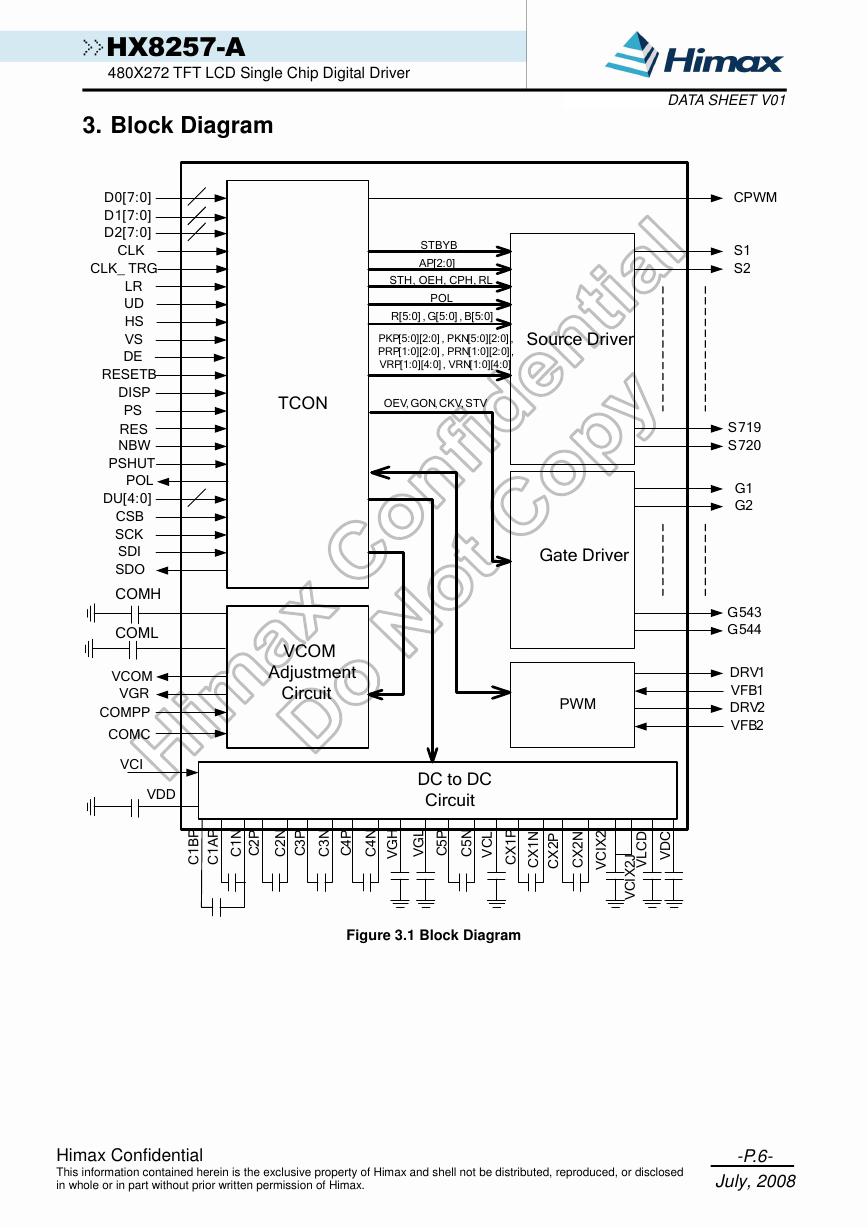
3. Block Diagram
DATA SHEET V01
2
3# 3#3#
3# 3#
3# 3#
3# 3#
3#
% )’(+ #’&, + ’
3 3 3
#
-.)/$0 + 1 $#
&’()&$
* $+ #’&, + ’
#$% ##
&’()&$
!
!
!
!
!
Figure 3.1 Block Diagram
"
!
4
4
Himax Confidential
This information contained herein is the exclusive property of Himax and shell not be distributed, reproduced, or disclosed
in whole or in part without prior written permission of Himax.
-P.6-
July, 2008
�
480X272 TFT LCD Single Chip Digital Driver
4. Pad Assignment
DATA SHEET V01
THROUGH5 (1)
DUMMY (1)
THROUGH6 (1)
DUMMY (1)
G2
G4
G6
G8
G538
G540
G542
G544
DUMMY
PRT4
PRT3
PRT2
PRT1
DUMMY
S1
S2
S3
S359
S360
DUMMY (5)
S361
S362
S716
S717
S718
S719
S720
DUMMY
PLT1
PLT2
PLT3
PLT4
DUMMY
G543
G541
G539
G537
G7
G5
G3
G1
DUMMY (1)
THROUGH7 (1)
DUMMY (1)
THROUGH8 (1)
VCOM (4)
PRB4 (1)
PRB3 (1)
PRB2 (1)
PRB1 (1)
TEST1 (1)
TEST2 (1)
TEST3 (1)
TEST4 (1)
TEST5 (1)
TEST6 (1)
TEST7 (1)
TEST8 (1)
DU0 (1)
DU1 (1)
DU2 (1)
DU3 (1)
DU4 (1)
DUMMY (1)
CPWM (1)
RES (1)
DVSS (1)
NBW (1)
SDO (1)
SDI (1)
SCL (1)
CSB (1)
PS (1)
CLK_TRG (1)
LR (1)
UD (1)
DE (1)
VS (1)
HS (1)
DISP (1)
CLK (2)
DUMMY (1)
D27 (2)
D26 (2)
D25 (2)
D24 (2)
D23 (2)
D22 (2)
D21 (2)
D20 (2)
D17 (2)
D16 (2)
D15 (2)
D14 (2)
D13 (2)
D12 (2)
D11 (2)
D10 (2)
DUMMY (1)
D07 (2)
D06 (2)
D05 (2)
D04 (2)
D03 (2)
D02 (2)
D01 (2)
D00 (2)
RESETB (1)
POL (1)
PSHUT (1)
DVSS (6)
VDDIO (6)
TEST9 (1)
TEST10 (1)
VCIP (3)
VCI (7)
VDD (5)
VSSRC (4)
EXVR (3)
VLCD (3)
CX1P (5)
CX1N (5)
CX2P (5)
CX2N (5)
VCIX2 (5)
VCIX2J (5)
VDC (5)
AVSS (6)
VCHS (7)
PSW (5)
VGL (3)
C4N (3)
C3N (3)
C3P (3)
C4P (3)
C2N (3)
C1N (3)
C1BP (3)
C1AP (3)
C2P (3)
VGH (3)
VCL (5)
C5N (5)
C5P (5)
VGR (3)
COMPP (1)
COMC (1)
COMH (4)
COML (4)
DRV1 (1)
VFB1 (1)
DRV2 (1)
VFB2 (1)
PLB1 (1)
PLB2 (1)
PLB3 (1)
PLB4 (1)
VCOM (4)
Himax Confidential
This information contained herein is the exclusive property of Himax and shell not be distributed, reproduced, or disclosed
in whole or in part without prior written permission of Himax.
-P.7-
July, 2008
�




 V2版本原理图(Capacitive-Fingerprint-Reader-Schematic_V2).pdf
 摄像头工作原理.doc
 VL53L0X简要说明(En.FLVL53L00216).pdf
 原理图(DVK720-Schematic).pdf
 原理图(Pico-Clock-Green-Schdoc).pdf
 原理图(RS485-CAN-HAT-B-schematic).pdf
 File:SIM7500_SIM7600_SIM7800 Series_SSL_Application Note_V2.00.pdf
 ADS1263(Ads1262).pdf
 原理图(Open429Z-D-Schematic).pdf
 用户手册(Capacitive_Fingerprint_Reader_User_Manual_CN).pdf
 CY7C68013A(英文版)(CY7C68013A).pdf
 TechnicalReference_Dem.pdf