�
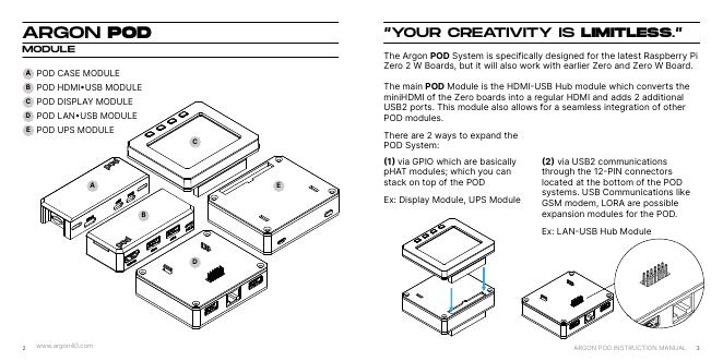
ARGON POD
MODULE
A
B
C
D
E
POD CASE MODULE
POD HDMI�USB MODULE
POD DISPLAY MODULE
POD LAN�USB MODULE
POD UPS MODULE
A
B
E
C
D
“YOUR CREATIVITY IS LIMITLESS.”
The Argon POD System is specifically designed for the latest Raspberry Pi
Zero 2 W Boards, but it will also work with earlier Zero and Zero W Board.
The main POD Module is the HDMI�USB Hub module which converts the
miniHDMI of the Zero boards into a regular HDMI and adds 2 additional
USB2 ports. This module also allows for a seamless integration of other
POD modules.
There are 2 ways to expand the
POD System:
�1� via GPIO which are basically
pHAT modules; which you can
stack on top of the POD
Ex: Display Module, UPS Module
�2� via USB2 communications
through the 12�PIN connectors
located at the bottom of the POD
systems. USB Communications like
GSM modem, LORA are possible
expansion modules for the POD.
Ex: LAN�USB Hub Module
2
www.argon40.com
ARGON POD INSTRUCTION MANUAL
3
ARGON POD CASE
MODULE
1
2
B
E
D
A
C
F
*RASPBERRY PI BOARD
NOT INCLUDED
3
4
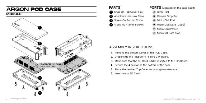
PARTS
1
Snap On Top Cover Flat
Aluminum Heatsink Case
Screw On Bottom Cover
4 pcs M2 � 8mm screws
2
3
4
PORTS �Located on the case itself)
A
B
C
D
E
F
GPIO Port
Camera Strip Port
Mini HDMI Port
Micro USB Data (USB2�
Micro USB Power
Micro SD Card Slot
ASSEMBLY INSTRUCTIONS
1.
2.
3.
4.
5.
6.
Remove the Bottom Cover of the POD Case.
Drop inside the Raspberry Pi Zero 2 W Board.
Make sure that the SD Card is NOT inserted to the RPi Board.
Secure the 4 screws at the bottom of the case.
Place the desired Top Cover for your given use case.
Insert micro SD Card.
4
www.argon40.com
ARGON POD INSTRUCTION MANUAL
5
�
ARGON POD HDMI•USB
MODULE
1
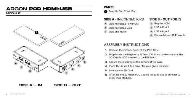
PARTS
1
Snap On Top Cover Flat
SIDE A � IN CONNECTORS
A
B
C
Male microUSB Power OUT
Male microUSB Data
Male Mini HDMI
SIDE B � OUT PORTS
D
E
F
G
Regular HDMI
USB A Port 1
USB A Port 2
Female MicroUSB Power IN
A
B
C
G
F
E
D
3.
4.
5.
6.
SIDE A - IN
SIDE B - OUT
ASSEMBLY INSTRUCTIONS
1.
2.
Remove the Bottom Cover of the POD Case.
Drop inside the Raspberry Pi Zero 2 W Board. Make sure that the
SD Card is NOT inserted to the RPi Board.
Secure the 4 screws at the bottom of the case.
Place the desired Top Cover for your given use case.
Insert micro SD Card
After assembly, Argon POD Case is ready to use or connect to
other POD Modules
6
www.argon40.com
ARGON POD INSTRUCTION MANUAL
7
�
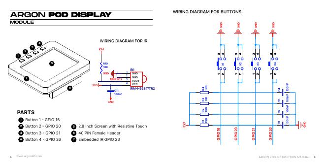
ARGON POD DISPLAY
MODULE
WIRING DIAGRAM FOR BUTTONS
D
N
G
D
N
G
D
N
G
D
N
G
4
3
5
2
1
7
PARTS
1
Button 1 � GPIO 16
Button 2 � GPIO 20
Button 3 � GPIO 21
Button 4 � GPIO 26
2
3
4
WIRING DIAGRAM FOR IR
3V3
R19
10K
GND
GPIO23
C11
100nF
GND
1
2
3
4
IR1
GND
GND
VOUT
VCC
IRM�H638T/TR2
6
3V3
5
6
7
2.8 Inch Screen with Resistive Touch
40 PIN Female Header
Embedded IR GPIO 23
1
K
2
K
3
K
4
K
K
0
1
4
R
K
0
1
3
R
K
0
1
2
R
K
0
1
1
R
3
V
3
F
n
0
0
1
F
n
0
0
1
F
n
0
0
1
F
n
0
0
1
4
C
3
C
2
C
1
C
D
N
G
6
1
O
P
G
I
0
2
O
P
G
I
1
2
O
P
G
I
6
2
O
P
G
I
8
www.argon40.com
ARGON POD INSTRUCTION MANUAL
9
�
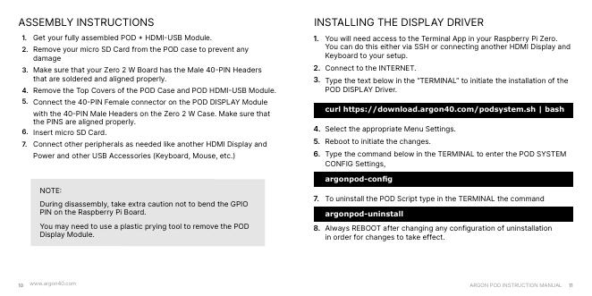
ASSEMBLY INSTRUCTIONS
1.
2.
Get your fully assembled POD � HDMI�USB Module.
Remove your micro SD Card from the POD case to prevent any
damage
Make sure that your Zero 2 W Board has the Male 40�PIN Headers
that are soldered and aligned properly.
Remove the Top Covers of the POD Case and POD HDMI�USB Module.
Connect the 40�PIN Female connector on the POD DISPLAY Module
with the 40�PIN Male Headers on the Zero 2 W Case. Make sure that
the PINS are aligned properly.
Insert micro SD Card.
Connect other peripherals as needed like another HDMI Display and
Power and other USB Accessories (Keyboard, Mouse, etc.)
3.
4.
5.
6.
7.
NOTE�
During disassembly, take extra caution not to bend the GPIO
PIN on the Raspberry Pi Board.
You may need to use a plastic prying tool to remove the POD
Display Module.
INSTALLING THE DISPLAY DRIVER
1.
You will need access to the Terminal App in your Raspberry Pi Zero.
You can do this either via SSH or connecting another HDMI Display and
Keyboard to your setup.
Connect to the INTERNET.
Type the text below in the “TERMINAL” to initiate the installation of the
POD DISPLAY Driver.
curl https://download.argon40.com/podsystem.sh | bash
Select the appropriate Menu Settings.
Reboot to initiate the changes.
Type the command below in the TERMINAL to enter the POD SYSTEM
CONFIG Settings,
argonpod-config
To uninstall the POD Script type in the TERMINAL the command
argonpod-uninstall
Always REBOOT after changing any configuration of uninstallation
in order for changes to take effect.
2.
3.
4.
5.
6.
7.
8.
10
www.argon40.com
ARGON POD INSTRUCTION MANUAL
11
�
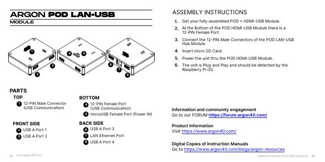
ARGON POD LAN•USB
MODULE
4
5
1
2
3
6
7
8
PARTS
TOP
1
12�PIN Male Connector
�USB Communication)
FRONT SIDE
2
3
USB A Port 1
USB A Port 2
12
www.argon40.com
BOTTOM
4
5
12�PIN Female Port
�USB Communication)
microUSB Female Port (Power IN�
BACK SIDE
6
7
8
USB A Port 3
LAN Ethernet Port
USB A Port 4
ASSEMBLY INSTRUCTIONS
1.
2.
Get your fully assembled POD � HDMI�USB Module.
At the Bottom of the POD HDMI�USB Module there is a
12�PIN Female Port.
Connect the 12�PIN Male Connectors of the POD LAN�USB
Hub Module.
Insert micro SD Card.
Power the unit thru the POD HDMI�USB Module.
The unit is Plug and Play and should be detected by the
Raspberry Pi OS.
3.
4.
5.
6.
Information and community engagement
Go to our FORUM https://forum.argon40.com/
Product Information
Visit https://www.argon40.com/
Digital Copies of Instruction Manuals
Go to https://www.argon40.com/blogs/argon-resources
ARGON POD INSTRUCTION MANUAL
13
�
LET US CAST
SOME MAGIC.
POLY+
VENTED
ARGON ONE M.2
SATA | NVMe
EON
Pi NAS
ARGON
ONE V2
NEO
�



 V2版本原理图(Capacitive-Fingerprint-Reader-Schematic_V2).pdf
 摄像头工作原理.doc
 VL53L0X简要说明(En.FLVL53L00216).pdf
 原理图(DVK720-Schematic).pdf
 原理图(Pico-Clock-Green-Schdoc).pdf
 原理图(RS485-CAN-HAT-B-schematic).pdf
 File:SIM7500_SIM7600_SIM7800 Series_SSL_Application Note_V2.00.pdf
 ADS1263(Ads1262).pdf
 原理图(Open429Z-D-Schematic).pdf
 用户手册(Capacitive_Fingerprint_Reader_User_Manual_CN).pdf
 CY7C68013A(英文版)(CY7C68013A).pdf
 TechnicalReference_Dem.pdf