FT4232H QUAD HIGH SPEED USB TO MULTIPURPOSE UART/MPSSE IC
Datasheet
Version 2.6
Document No.: FT_000060 Clearance No.: FTDI#78
Future Technology
Devices International Ltd
FT4232H Quad High Speed
USB to Multipurpose
UART/MPSSE IC
The FT4232H is FTDI’s 5th generation of USB devices.
The FT4232H is a USB 2.0 High Speed (480Mb/s) to
UART/MPSSE ICs. The device features 4 UARTs. Two
of these have an option to independently configure
an MPSSE engine. This allows the FT4232H to
operate as two UART/Bit-Bang ports plus two MPSSE
engines used to emulate JTAG, SPI, I2C, Bit-bang or
other synchronous serial modes. The FT4232H has
the following advanced features:
Single chip USB to quad serial ports with a
variety of configurations.
Entire USB protocol handled on the chip. No USB
specific firmware programming required.
USB 2.0 High Speed (480Mbits/Second) and Full
Speed (12Mbits/Second) compatible.
Two Multi-Protocol Synchronous Serial Engine
(MPSSE) on channel A and channel B, to simplify
synchronous serial protocol (USB to JTAG, I2C,
SPI or bit-bang) design.
Independent Baud rate generators.
RS232/RS422/RS485 UART Transfer Data Rate
up to 12Mbaud. (RS232 Data Rate limited by
external level shifter).
FTDI’s royalty-free Virtual Com Port (VCP) and
Direct (D2XX) drivers eliminate the requirement
for USB driver development in most cases.
Highly integrated design includes +1.8V LDO
regulator for VCORE, integrated POR function
and on chip clock multiplier PLL (12MHz –
480MHz).
FTDI FT232B style, asynchronous serial UART
interface option with full hardware handshaking
and modem interface signals.
Fully assisted hardware or X-On / X-Off software
handshaking.
UART Interface supports 7/8 bit data, 1/2 stop
bits, and Odd/Even/Mark/Space/No Parity.
Auto-transmit enable control for RS485 serial
applications using TXDEN pin.
Operational
configuration mode and USB
in external
Description strings configurable
EEPROM over the USB interface.
Low operating and USB suspend current.
Configurable I/O drive strength (4, 8, 12 or
16mA) and slew rate.
Supports bus powered, self-powered and high-
power bus powered USB configurations.
UHCI/OHCI/EHCI host controller compatible.
USB Bulk data transfer mode (512 byte packets
in High Speed mode).
Dedicated Windows DLLs available for USB to
JTAG, USB to SPI, and USB to I2C applications.
+1.8V (chip core) and +3.3V I/O interfacing
Optional traffic TX/RX indicators can be added
with LEDs and an external 74HC595 shift
register.
(+5V Tolerant).
Extended -40°C to 85°C industrial operating
temperature range.
Adjustable receive buffer timeout.
Support for USB suspend and resume conditions
Compact 64-LD Lead Free LQFP or QFN package
Available in compact Pb-free 56 Pin VQFN
via PWREN#, SUSPEND# and RI# pins.
packages (RoHS compliant)
+3.3V single supply operating voltage range.
ESD protection for FT4232H IO’s:
Human Body Model (HBM) ±2kV,
Machine Mode (MM) ±200V,
Charge Device Model (CDM) ±500V,
Latch-up free.
Neither the whole nor any part of the information contained in, or the product described in this manual, may be adapted or reproduced in
any material or electronic form without the prior written consent of the copyright holder. This product and its documentation are supplied
on an as-is basis and no warranty as to their suitability for any particular purpose is either made or implied. Future Technology Devices
International Ltd will not accept any claim for damages howsoever arising as a result of use or failure of this product. Your statutory rights
are not affected. This product or any variant of it is not intended for use in any medical appliance, device or system in which the failure of
the product might reasonably be expected to result in personal injury. This document provides preliminary information that may be subject
to change without notice. No freedom to use patents or other intellectual property rights is implied by the publication of this document.
Future Technology Devices International Ltd, Unit 1, 2 Seaward Place, Centurion Business Park, Glasgow, G41 1HH, United Kingdom.
Scotland Registered Number: SC136640
Copyright © Future Technology Devices International Limited
1
�
FT4232H QUAD HIGH SPEED USB TO MULTIPURPOSE UART/MPSSE IC
Datasheet
Version 2.6
Document No.: FT_000060 Clearance No.: FTDI#78
1 Typical Applications
Single chip USB to four channels UART (RS232,
RS422 or RS485) or Bit-Bang interfaces.
Numerous combinations of 4 channels.
Upgrading Legacy Peripheral Designs to USB
Single chip USB to 2 JTAG channels plus 2
UARTS.
Single chip USB to 1 JTAG channel plus 3
UARTS.
Single chip USB to 1 SPI channel plus 3 UARTS.
Single chip USB to 2 SPI channels plus 2
UARTS.
Single chip USB to 2 Bit-Bang channels plus 2
UARTS.
Single chip USB to 1 SPI channel, plus 1 JTAG
channel plus 2 UARTS.
Single chip USB to 2 I2C channels plus 2
UARTS.
1.1 Driver Support
Field Upgradable USB Products
Cellular and cordless phone USB data transfer
cables and interfaces.
Interfacing MCU / PLD / FPGA based designs to
USB
PDA to USB data transfer
USB Smart Card Readers
USB Instrumentation
USB Industrial Control
USB MP3 Player Interface
USB FLASH Card Reader / Writers
Set Top Box PC - USB interface
USB Digital Camera Interface
USB Bar Code Readers
The FT4232H requires USB drivers (listed below), available free from http://www.ftdichip.com, which are
used to make the FT4232H appear as a virtual COM port (VCP). This allows the user to communicate with
the USB interface via a standard PC serial emulation port (for example TTY). Another FTDI USB driver, the
D2XX driver, can also be used with application software to directly access the FT4232H through a DLL.
Royalty free VIRTUAL COM PORT
(VCP) DRIVERS for...
Royalty free D2XX Direct Drivers
(USB Drivers + DLL S/W Interface)
Windows 10 32,64-bit
Windows 10 32,64-bit
Windows 8/8.1 32,64-bit
Windows 8/8.1 32,64-bit
Windows 7 32,64-bit
Windows 7 32,64-bit
Windows Vista and Vista 64-bit
Windows Vista and Vista 64-bit
Windows XP and XP 64-bit
Windows XP and XP 64-bit
Windows 98, 98SE, ME, 2000, Server 2003, XP,
Windows 98, 98SE, ME, 2000, Server 2003, XP,
Server 2008 and server 2012 R2
Server 2008 and server 2012 R2
Windows XP Embedded
Windows XP Embedded
Windows CE 4.2, 5.0 and 6.0
Windows CE 4.2, 5.0 and 6.0
Mac OS 8/9, OS-X
Linux 2.4 and greater
Linux 2.4 and greater
Android(J2xx)
For driver installation, please refer to the installation guides on our website:
http://www.ftdichip.com/Support/Documents/InstallGuides.htm
The following additional installation guides application notes and technical notes are also available:
AN_113, “Interfacing FT2232H Hi-Speed Devices To I2C Bus”.
AN_109 – “Programming Guide for High Speed FTCI2C DLL”
AN_110 – “Programming Guide for High Speed FTCJTAG DLL”
AN_111 – “Programming Guide for High Speed FTCSPI DLL”
AN 113 – “Interfacing FT2232H Hi-Speed Devices To I2C Bus”
AN114 – “Interfacing FT2232H Hi-Speed Devices To SPI Bus”
AN135 – MPSSE Basics
AN108 - Command Processor For MPSSE and MCU Host Bus Emulation Modes
Copyright © Future Technology Devices International Limited
2
�
FT4232H QUAD HIGH SPEED USB TO MULTIPURPOSE UART/MPSSE IC
Datasheet
Version 2.6
Document No.: FT_000060 Clearance No.: FTDI#78
TN_104, “Guide to Debugging Customers Failed Driver Installation”
1.2 Part Numbers
Part Number
Package
64 Pin LQFP
64 Pin QFN
56 Pin VQFN
FT4232HL-XXXX
FT4232HQ-XXXX
FT4232H-56Q-XXXX
Note: Packaging codes for xxxx is:
- Reel: Taped and Reel (LQFP =1000 pcs per reel, QFN-64 =4000 pcs per reel, QFN-56 = 3000 pcs per
reel)
- Tray: Tray packing, (LQFP =160 pcs per tray, QFN-64 =260 pcs per tray, QFN-56 = 260 pcs per tray)
Please refer to section 8 for all package mechanical parameters.
1.3 USB Compliant
The FT4232H is fully compliant with the USB 2.0 specification and has been given the USB-IF Test-ID (TID)
40720024.
The timing of the rise/fall time of the USB signals is not only dependant on the USB signal drivers, it is also
dependant system and is affected by factors such as PCB layout, external components and any transient
protection present on the USB signals. For USB compliance these may require a slight adjustment. This
timing can be modified through a programmable setting stored in the same external EEPROM that is used
for the USB descriptors. Timing can also be changed by adding appropriate passive components to the
USB signals.
Copyright © Future Technology Devices International Limited
3
�
FT4232H QUAD HIGH SPEED USB TO MULTIPURPOSE UART/MPSSE IC
Datasheet
Version 2.6
Document No.: FT_000060 Clearance No.: FTDI#78
2 FT4232H Block Diagram
For a description of each function please refer to Section 4.
Figure 2.1 FT4232H Block Diagram
Copyright © Future Technology Devices International Limited
4
120 MHzDual Port TXBuffer 2K BytesDual Port RXBuffer 2K BytesBaud RateGeneratorMulti- purpose UART/bit-bang ControllerADBUS0ADBUS1ADBUS2ADBUS3ADBUS4ADBUS5ADBUS6ADBUS7120 MHzDual Port TXBuffer 2K BytesDual Port RXBuffer 2K BytesBaud RateGeneratorMulti- purpose UART/bit-bang ControllerBDBUS0BDBUS1BDBUS2BDBUS3BDBUS4BDBUS5BDBUS6BDBUS7120 MHzDual Port TXBuffer 2K BytesDual Port RXBuffer 2K BytesBaud RateGeneratorMulti- purpose UART/bit-bang ControllerCDBUS0CDBUS1CDBUS2CDBUS3CDBUS4CDBUS5CDBUS6CDBUS7120 MHzDual Port TXBuffer 2K BytesDual Port RXBuffer 2K BytesBaud RateGeneratorMulti- purpose UART/bit-bang ControllerDDBUS0DDBUS1DDBUS2DDBUS3DDBUS4DDBUS5DDBUS6DDBUS7120 MHz120 MHz120 MHz120 MHzUSB Protocol EngineAnd FIFO ControlUTMI PHYUSBDMUSBDPRREFRESETGeneratorRESET#TESTOSCIOSCO1.8 VoltLDORegulatorVCC 3V3 INV1.8OUTEEPROMInterfaceEECSEESKEEDATAPWREN#SUSPEND#MPSSE/MPSSE/�
FT4232H QUAD HIGH SPEED USB TO MULTIPURPOSE UART/MPSSE IC
Datasheet
Version 2.6
Document No.: FT_000060 Clearance No.: FTDI#78
Table of Contents
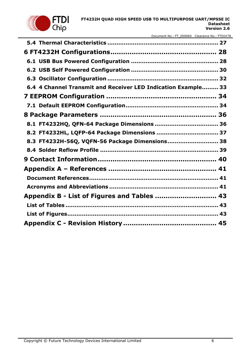
1 Typical Applications .......................................................... 2
1.1 Driver Support ............................................................................. 2
1.2 Part Numbers ............................................................................... 3
1.3 USB Compliant ............................................................................. 3
2 FT4232H Block Diagram .................................................... 4
3 Device Pin Out and Signal Description ............................... 7
3.1 64-pin LQFP and QFN Package ..................................................... 7
3.1.1 Schematic Symbol ....................................................................................... 7
3.1.2 Pin Descriptions ........................................................................................... 7
3.1.3 Common Pins .............................................................................................. 9
3.1.4 Configured Pins ......................................................................................... 10
3.2 56-pin VQFN Package ................................................................ 11
3.2.1 Schematic Symbol for FT4232H-56Q ............................................................ 12
3.2.2 Pin Descriptions for FT4232H-56Q................................................................ 12
3.2.3 Common Pins for FT4232H-56Q ................................................................... 14
3.2.4 Configured Pins for FT4232H-56Q ................................................................ 15
4 Function Description ....................................................... 17
4.1 Key Features .............................................................................. 17
4.2 Functional Block Descriptions .................................................... 17
4.3 FT232 UART Interface Mode Description .................................... 18
4.3.1 RS232 Configuration .................................................................................. 18
4.3.2 RS422 Configuration .................................................................................. 19
4.3.3 RS485 Configuration .................................................................................. 20
4.4 MPSSE Interface Mode Description ............................................ 21
4.4.1 MPSSE Adaptive Clocking ............................................................................ 22
4.5 Synchronous & Asynchronous Bit-Bang Interface Mode Desc. ... 23
4.5.1 Asynchronous Bit-Bang Mode ...................................................................... 23
4.5.2 Synchronous Bit-Bang Mode ........................................................................ 23
4.6 FT4232H Mode Selection ............................................................ 24
5 Devices Characteristics and Ratings ................................ 25
5.1 Absolute Maximum Ratings ........................................................ 25
5.2 DC Characteristics ...................................................................... 25
5.3 ESD Tolerance ............................................................................ 27
Copyright © Future Technology Devices International Limited
5
�
FT4232H QUAD HIGH SPEED USB TO MULTIPURPOSE UART/MPSSE IC
Datasheet
Version 2.6
Document No.: FT_000060 Clearance No.: FTDI#78
5.4 Thermal Characteristics ............................................................. 27
6 FT4232H Configurations .................................................. 28
6.1 USB Bus Powered Configuration ................................................ 28
6.2 USB Self Powered Configuration ................................................ 30
6.3 Oscillator Configuration ............................................................. 32
6.4 4 Channel Transmit and Receiver LED Indication Example ......... 33
7 EEPROM Configuration .................................................... 34
7.1 Default EEPROM Configuration ................................................... 34
8 Package Parameters ....................................................... 36
8.1 FT4232HQ, QFN-64 Package Dimensions ................................... 36
8.2 FT4232HL, LQFP-64 Package Dimensions .................................. 37
8.3 FT4232H-56Q, VQFN-56 Package Dimensions ............................ 38
8.4 Solder Reflow Profile ................................................................. 39
9 Contact Information ........................................................ 40
Appendix A – References ................................................... 41
Document References ....................................................................... 41
Acronyms and Abbreviations ............................................................ 41
Appendix B - List of Figures and Tables ............................. 43
List of Tables .................................................................................... 43
List of Figures ................................................................................... 43
Appendix C - Revision History ............................................ 45
Copyright © Future Technology Devices International Limited
6
�
FT4232H QUAD HIGH SPEED USB TO MULTIPURPOSE UART/MPSSE IC
Datasheet
Version 2.6
Document No.: FT_000060 Clearance No.: FTDI#78
3 Device Pin Out and Signal Description
3.1 64-pin LQFP and QFN Package
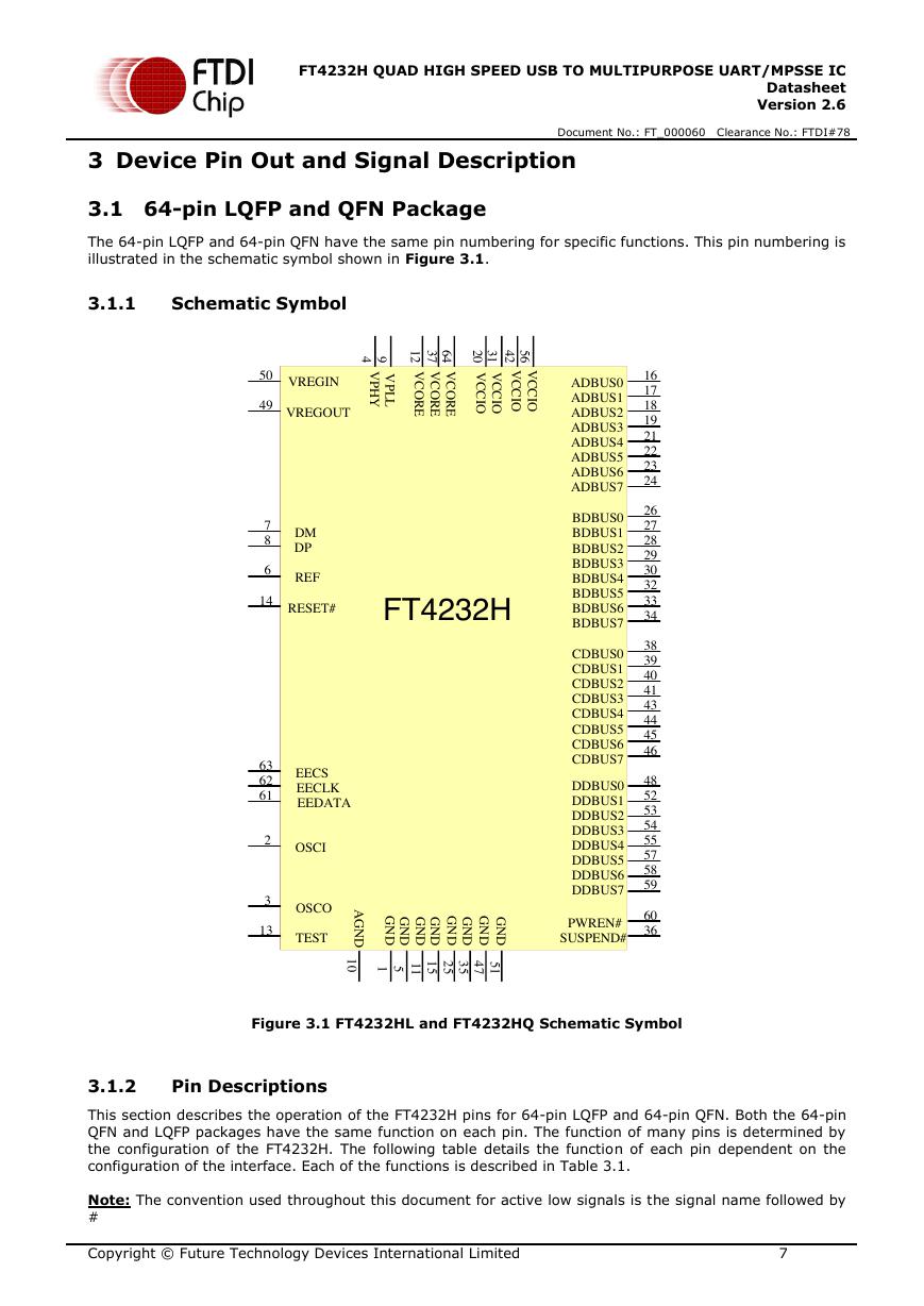
The 64-pin LQFP and 64-pin QFN have the same pin numbering for specific functions. This pin numbering is
illustrated in the schematic symbol shown in Figure 3.1.
3.1.1
Schematic Symbol
Figure 3.1 FT4232HL and FT4232HQ Schematic Symbol
3.1.2
Pin Descriptions
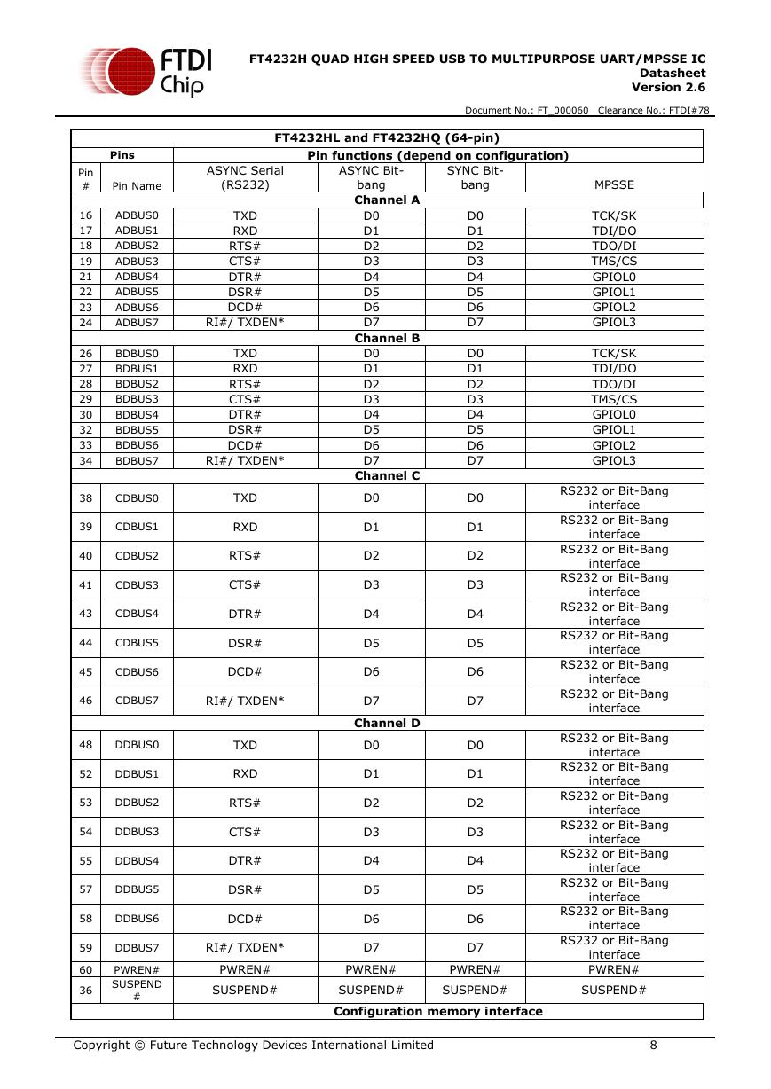
This section describes the operation of the FT4232H pins for 64-pin LQFP and 64-pin QFN. Both the 64-pin
QFN and LQFP packages have the same function on each pin. The function of many pins is determined by
the configuration of the FT4232H. The following table details the function of each pin dependent on the
configuration of the interface. Each of the functions is described in Table 3.1.
Note: The convention used throughout this document for active low signals is the signal name followed by
#
Copyright © Future Technology Devices International Limited
7
GND1OSCI2OSCO3VPHY4GND5REF6DM7DP8VPLL9AGND10GND11VCORE12TEST13RESET#14GND15ADBUS016ADBUS117ADBUS218ADBUS319VCCIO20ADBUS421ADBUS522ADBUS623ADBUS724GND252627282930VCCIO31323334GND35SUSPEND#36VCORE37BDBUS038BDBUS139BDBUS240BDBUS341VCCIO42BDBUS443BDBUS544BDBUS645BDBUS746GND4748VREGOUT49VREGIN50GND51525354VCCIO5655575859PWREN#60EECLK62EEDATA61EECS63VCORE64 FT4232HCDBUS0CDBUS1CDBUS2CDBUS3CDBUS4CDBUS5CDBUS6CDBUS7DDBUS0DDBUS1DDBUS2DDBUS3DDBUS4DDBUS5DDBUS6DDBUS7�
FT4232H QUAD HIGH SPEED USB TO MULTIPURPOSE UART/MPSSE IC
Datasheet
Version 2.6
Document No.: FT_000060 Clearance No.: FTDI#78
FT4232HL and FT4232HQ (64-pin)
Pins
Pin Name
ASYNC Serial
(RS232)
Pin functions (depend on configuration)
ASYNC Bit-
bang
Channel A
SYNC Bit-
bang
D0
D1
D2
D3
D4
D5
D6
D7
Channel B
D0
D1
D2
D3
D4
D5
D6
D7
Channel C
D0
D1
D2
D3
D4
D5
D6
D7
Channel D
D0
D1
D2
D3
D4
D5
D6
D7
D0
D1
D2
D3
D4
D5
D6
D7
D0
D1
D2
D3
D4
D5
D6
D7
D0
D1
D2
D3
D4
D5
D6
D7
D0
D1
D2
D3
D4
D5
D6
D7
MPSSE
TCK/SK
TDI/DO
TDO/DI
TMS/CS
GPIOL0
GPIOL1
GPIOL2
GPIOL3
TCK/SK
TDI/DO
TDO/DI
TMS/CS
GPIOL0
GPIOL1
GPIOL2
GPIOL3
RS232 or Bit-Bang
interface
RS232 or Bit-Bang
interface
RS232 or Bit-Bang
interface
RS232 or Bit-Bang
interface
RS232 or Bit-Bang
interface
RS232 or Bit-Bang
interface
RS232 or Bit-Bang
interface
RS232 or Bit-Bang
interface
RS232 or Bit-Bang
interface
RS232 or Bit-Bang
interface
RS232 or Bit-Bang
interface
RS232 or Bit-Bang
interface
RS232 or Bit-Bang
interface
RS232 or Bit-Bang
interface
RS232 or Bit-Bang
interface
RS232 or Bit-Bang
interface
PWREN#
Pin
#
16
17
18
19
21
22
23
24
26
27
28
29
30
32
33
34
ADBUS0
ADBUS1
ADBUS2
ADBUS3
ADBUS4
ADBUS5
ADBUS6
ADBUS7
BDBUS0
BDBUS1
BDBUS2
BDBUS3
BDBUS4
BDBUS5
BDBUS6
BDBUS7
38
CDBUS0
39
CDBUS1
40
CDBUS2
41
CDBUS3
43
CDBUS4
44
CDBUS5
45
CDBUS6
TXD
RXD
RTS#
CTS#
DTR#
DSR#
DCD#
RI#/ TXDEN*
TXD
RXD
RTS#
CTS#
DTR#
DSR#
DCD#
RI#/ TXDEN*
TXD
RXD
RTS#
CTS#
DTR#
DSR#
DCD#
46
CDBUS7
RI#/ TXDEN*
48
DDBUS0
52
DDBUS1
53
DDBUS2
54
DDBUS3
55
DDBUS4
57
DDBUS5
58
DDBUS6
TXD
RXD
RTS#
CTS#
DTR#
DSR#
DCD#
59
DDBUS7
RI#/ TXDEN*
60
36
PWREN#
SUSPEND
#
PWREN#
PWREN#
PWREN#
SUSPEND#
SUSPEND#
SUSPEND#
SUSPEND#
Configuration memory interface
Copyright © Future Technology Devices International Limited
8
�



 V2版本原理图(Capacitive-Fingerprint-Reader-Schematic_V2).pdf
 摄像头工作原理.doc
 VL53L0X简要说明(En.FLVL53L00216).pdf
 原理图(DVK720-Schematic).pdf
 原理图(Pico-Clock-Green-Schdoc).pdf
 原理图(RS485-CAN-HAT-B-schematic).pdf
 File:SIM7500_SIM7600_SIM7800 Series_SSL_Application Note_V2.00.pdf
 ADS1263(Ads1262).pdf
 原理图(Open429Z-D-Schematic).pdf
 用户手册(Capacitive_Fingerprint_Reader_User_Manual_CN).pdf
 CY7C68013A(英文版)(CY7C68013A).pdf
 TechnicalReference_Dem.pdf