DATA SHEET
( DOC No. HX8347-D(T)-DS )
HX8347-D(T)
240RGB x 320 dot, 262K color,
with internal GRAM,
TFT Mobile Single Chip Driver
Preliminary version 01 ,October 2008
�
HX8347-D(T)
240RGB x 320 dot, 262K color, with internal
GRAM, TFT Mobile Single Chip Driver
List of Contents
October, 2008
1. General Description ............................................................................................................................... 10
2. Features....................................................................................................................................................11
3. Block Diagram ........................................................................................................................................ 13
4. Pin Description ....................................................................................................................................... 14
4.1 Pin Description..................................................................................................................................... 14
4.2 Pin Assignment .................................................................................................................................... 17
4.3 PAD Coordinates.................................................................................................................................. 18
4.4 Alignment Mark .................................................................................................................................... 24
4.5 Bump Size............................................................................................................................................. 25
5. Interface................................................................................................................................................... 26
5.1 System Interface Circuit...................................................................................................................... 27
5.1.1 Parallel Bus System Interface ......................................................................................................... 28
5.1.2 MCU Data Color Coding.................................................................................................................. 30
5.1.3 Serial Bus System Interface ............................................................................................................ 43
5.1.3.1 3-wire serial interface ................................................................................................................... 43
5.1.3.2 4-wire serial interface ................................................................................................................... 44
5.2 RGB Interface ....................................................................................................................................... 46
5.2.1 Color Order on RGB Interface......................................................................................................... 50
5.2.2 RGB Data Color Coding .................................................................................................................. 51
6. Display Data GRAM ................................................................................................................................ 54
6.1 Display Data GRAM Mapping.............................................................................................................. 54
6.2 Address Counter (AC) of GRAM ......................................................................................................... 55
6.2.1 System interface to GRAM Write Direction ..................................................................................... 56
6.3 GRAM to Display Address Mapping................................................................................................... 61
6.3.1 Normal Display On or Partial Mode On, Vertical Scroll Off ............................................................. 63
6.3.2 Vertical Scroll Display Mode............................................................................................................ 65
6.3.3 Updating Order on Display Active Area in RGB Interface Mode ..................................................... 68
7. Functional Description .......................................................................................................................... 71
7.1 Internal Oscillator................................................................................................................................. 71
7.2 Gamma Characteristic Correction Function ..................................................................................... 72
7.3 Tearing Effect Output Line .................................................................................................................. 92
7.3.1 Tearing Effect Line Modes ............................................................................................................... 92
7.3.2 Tearing Effect Line Timing ............................................................................................................... 93
7.3.3 Example 1: MPU Write is faster than Panel Read .......................................................................... 94
7.3.4 Example 2: MPU Write is slower than Panel Read ......................................................................... 95
7.4 Content Adaptive Brightness Control (CABC) Function ................................................................. 96
7.4.1 Module Architectures....................................................................................................................... 97
7.4.2 Brightness Control Block ................................................................................................................. 98
7.4.3 Minimum Brightness Setting of CABC Function.............................................................................. 99
7.4.4 Display Dimming ............................................................................................................................. 99
7.5 LCD Power Generation Circuit ......................................................................................................... 100
7.5.1 Power Supply Circuit ..................................................................................................................... 100
7.5.2 LCD Power Generation Scheme................................................................................................... 102
7.6 Power On/Off Sequence .................................................................................................................... 103
7.7 Input / Output Pin State ..................................................................................................................... 107
7.7.1 Output Pins.................................................................................................................................... 107
7.7.2 Input Pins....................................................................................................................................... 107
8. Command .............................................................................................................................................. 108
8.1 Command Set ..................................................................................................................................... 109
Himax Confidential
This information contained herein is the exclusive property of Himax and shall not be distributed, reproduced, or disclosed
in whole or in part without prior written permission of Himax.
-P.1-
October, 2008
�
October, 2008
HX8347-D(T)
240RGB x 320 dot, 262K color, with internal
GRAM, TFT Mobile Single Chip Driver
List of Contents
8.2 Index Register .....................................................................................................................................113
8.3 Himax ID Register (PAGE0 - R00h)....................................................................................................113
8.4 Display Mode Control Register (PAGE0 -01h)..................................................................................113
8.5 Column Address Start Register (PAGE0 -02~03h)...........................................................................114
8.6 Column Address End Register (PAGE0 -04~05h) ............................................................................114
8.7 Row Address Start Register (PAGE0 -06~07h).................................................................................115
8.8 Row Address End Register (PAGE0 -08~09h) ..................................................................................115
8.9 Partial Area Start Row Register (PAGE0 -0A~0Bh)..........................................................................116
8.10 Partial Area End Row Register (PAGE0 -0C~0Dh) .........................................................................116
8.11 Vertical Scroll Top Fixed Area Register (PAGE0 -0E~0Fh)............................................................118
8.12 Vertical Scroll Height Area Register (PAGE0 -10~11h)..................................................................118
8.13 Vertical Scroll Button Fixed Area Register (PAGE0 -12~13h).......................................................118
8.14 Vertical Scroll Start Address Register (PAGE0 -14~15h) ............................................................. 120
8.15 Memory Access Control Register (PAGE0 -16h)........................................................................... 121
8.16 COLMOD Control Register (PAGE0 -17h) ...................................................................................... 122
8.17 OSC Control Register (PAGE0 -18h & R19h)................................................................................. 123
8.18 Power Control 1 Register (PAGE0 -1Ah)........................................................................................ 124
8.19 Power Control 2 Register (PAGE0 -1Bh)........................................................................................ 125
8.20 Power Control 3 Register (PAGE0 -1Ch)........................................................................................ 126
8.21 Power Control 4 Register (PAGE0 -1Dh)........................................................................................ 126
8.22 Power Control 5 Register (PAGE0 -1Eh)........................................................................................ 127
8.23 Power Control 6 Register (PAGE0 -1Fh) ........................................................................................ 127
8.24 Read Data Register (PAGE0 -22h) .................................................................................................. 129
8.25 VCOM Control 1~3 Register (PAGE0 -23~25h).............................................................................. 130
8.26 Display Control 1 Register (PAGE0 -26h~R28h) ........................................................................... 132
8.27 Frame Control Register (PAGE0 -29h~R2Ch)................................................................................ 135
8.28 Cycle Control Register (PAGE0 -2Dh~R2Eh) ................................................................................ 137
8.29 Display Inversion Register (PAGE0 -2Fh)...................................................................................... 138
8.30 RGB Interface Control Register (PAGE0 -31h~R34h) ................................................................... 139
8.31 Panel Characteristic Control Register (PAGE0 -36h) ................................................................... 141
8.32 OTP Register (PAGE0 -38h ~ R3Ah) ............................................................................................... 142
8.33 CABC Control 1~4 Register (PAGE0 -3Ch~3Fh) ........................................................................... 143
8.34 Gamma Control 1~35 Register (PAGE0 -40h~5Dh)....................................................................... 145
8.35 Mode Control Register (PAGE0 -60h)............................................................................................. 150
8.36 Power saving internal control register (PAGE0 -RE4h~RE7h) .................................................... 150
8.37 Source OP control (PAGE0 -RE8h~E9h) ........................................................................................ 151
8.38 Power control internal used (PAGE0 -REAh~ECh)....................................................................... 152
8.39 Command page select register (RFFh) .......................................................................................... 152
8.40 CABC control 5~7 register (PAGE1 – RC3h, RC5h, RC7h) .......................................................... 153
8.41 Gain select register 0~8 (PAGE1 – RCBh~D3h) ............................................................................ 154
9. Layout Recommendation .................................................................................................................... 156
10. OTP Table ............................................................................................................................................ 158
10.1 OTP Programming Flow .................................................................................................................. 158
11. Electrical Characteristic .................................................................................................................... 160
11.1 Absolute Maximum Ratings ............................................................................................................ 160
11.2 ESD Protection Level....................................................................................................................... 160
11.3 Maximum Layout Resistance .......................................................................................................... 161
11.4 DC Characteristics ........................................................................................................................... 162
11.4.1 Current Consumption................................................................................................................... 164
11.5 AC Characteristics ........................................................................................................................... 165
11.5.1 Parallel Interface Characteristics (8080-series MPU) ................................................................. 165
11.5.2 Serial Interface Characteristics.................................................................................................... 167
11.5.3 RGB Interface Characteristics ..................................................................................................... 168
-P.2-
Himax Confidential
This information contained herein is the exclusive property of Himax and shall not be distributed, reproduced, or disclosed
in whole or in part without prior written permission of Himax.
October, 2008
�
HX8347-D(T)
240RGB x 320 dot, 262K color, with internal
GRAM, TFT Mobile Single Chip Driver
List of Contents
11.6.4 Reset Input Timing....................................................................................................................... 170
12. Ordering Information ......................................................................................................................... 171
13. Revision History ................................................................................................................................. 171
October, 2008
Himax Confidential
This information contained herein is the exclusive property of Himax and shall not be distributed, reproduced, or disclosed
in whole or in part without prior written permission of Himax.
-P.3-
October, 2008
�
HX8347-D(T)
240RGB x 320 dot, 262K color, with internal
GRAM, TFT Mobile Single Chip Driver
List of Figures
October, 2008
Figure 5. 1 Register Read/Write Timing in Parallel Bus System Interface (for I80 Series MPU)............. 28
Figure 5. 2 GRAM Read/Write Timing in Parallel Bus System Interface (for I80 Series MPU) ............... 29
Figure 5. 3 Example of I80- System 18-bit Parallel Bus Interface ........................................................... 32
Figure 5. 4 Input Data Bus and GRAM Data Mapping in 18-Bit Bus System Interface with 18 Bit-Data
Input (“IM3, IM2, IM1, IM”=”1010” or “1000”) .................................................................................... 32
Figure 5. 5 Example of I80 System 16-bit Parallel Bus Interface type I................................................... 33
Figure 5. 6 Example of I80 System 16-bit Parallel Bus Interface type II.................................................. 33
Figure 5. 7 Input Data Bus and GRAM Data Mapping in 16-Bit Bus System Interface with 12 Bit-Data
Input (R17H=03h and “IM3, IM2, IM1, IM0”=”0000”) ........................................................................ 34
Figure 5. 8 Input Data Bus and GRAM Data Mapping in 16-Bit Bus System Interface with 16 Bit-Data
Input (R17H=05h and “IM3, IM2, IM1, IM0”=”0000”) ........................................................................ 34
Figure 5. 9 Input Data Bus and GRAM Data Mapping in 16-Bit Bus System Interface with 18(12+6)
Bit-Data Input (R17H=06h and “IM3, IM2, IM1, IM0”=”0000”) .......................................................... 34
Figure 5. 10 Input Data Bus and GRAM Data Mapping in 16-Bit Bus System Interface with 18(16+2)
Bit-Data Input (R17H=07h and “IM3, IM2, IM1, IM0”=”0000”) .......................................................... 34
Figure 5. 11 Input Data Bus and GRAM Data Mapping in 16-Bit Bus System Interface with 12 Bit-Data
Input (R17H=03h and “IM3, IM2, IM1, IM0”=”0010”) ........................................................................ 35
Figure 5. 12 Input Data Bus and GRAM Data Mapping in 16-Bit Bus System Interface with 16 Bit-Data
Input (R17H=05h and “IM3, IM2, IM1, IM0”=”0010”) ........................................................................ 35
Figure 5. 13 Input Data Bus and GRAM Data Mapping in 16-Bit Bus System Interface with 18(12+6)
Bit-Data Input (R17H=06h and “IM3, IM2, IM1, IM0”=”0010”) .......................................................... 35
Figure 5. 14 Input Data Bus and GRAM Data Mapping in 16-Bit Bus System Interface with 18(16+2)
Bit-Data Input (R17H=07h and “IM3, IM2, IM1, IM0”=”0010”) .......................................................... 35
Figure 5. 15 Example of I80 System 9-bit Parallel Bus Interface type I................................................... 36
Figure 5. 16 Example of I80 System 9-bit Parallel Bus Interface type II.................................................. 36
Figure 5. 17 Input Data Bus and GRAM Data Mapping in 9-Bit Bus System Interface with 18 Bit-Data
Input (R17H=06h and “IM3, IM2, IM1, IM0”=”1001”) ........................................................................ 37
Figure 5. 18 Input Data Bus and GRAM Data Mapping in 9-Bit Bus System Interface with 18 Bit-Data
Input (R17H=06h and “IM3, IM2, IM1, IM0”=”1011”)......................................................................... 37
Figure 5. 19 Example of I80- System 8-bit Parallel Bus Interface type I.................................................. 38
Figure 5. 20 Example of I80- System 8-bit Parallel Bus Interface type II................................................. 38
Figure 5. 21 Input Data Bus and GRAM Data Mapping in 8-Bit Bus System Interface with 12 Bit-Data
Input (R17H=03h and“IM3, IM2, IM1, IM0”=”0001”) ......................................................................... 39
Figure 5. 22 Input Data Bus and GRAM Data Mapping in 8-Bit Bus System Interface with 16 Bit-Data
Input (R17H=05h and “IM3, IM2, IM1, IM0”=”0001”) ........................................................................ 39
Figure 5. 23 Input Data Bus and GRAM Data Mapping in 8-Bit Bus System Interface with 18 Bit-Data
Input (R17H=06h and “IM3, IM2, IM1, IM0”=”0001”) ........................................................................ 39
Figure 5. 24 Input Data Bus and GRAM Data Mapping in 8-Bit Bus System Interface with 12 Bit-Data
Input (R17H=03h and“IM3, IM2, IM1, IM0”=”0011”).......................................................................... 40
Figure 5. 25 Input Data Bus and GRAM Data Mapping in 8-Bit Bus System Interface with 16 Bit-Data
Input (R17H=05h and “IM3, IM2, IM1, IM0”=”0011”)......................................................................... 40
Figure 5. 26 Input Data Bus and GRAM Data Mapping in 8-Bit Bus System Interface with 18 Bit-Data
Input (R17H=06h and “IM3, IM2, IM1, IM0”=”0011”)......................................................................... 40
Figure 5. 27 Index Register Read/Write Timing in 3-wire Serial Bus System Interface........................... 43
Figure 5. 28 Data Write Timing in 3-wire Serial Bus System Interface .................................................... 44
Figure 5. 29 Index Register Write Timing in 4-wire Serial Bus System Interface..................................... 44
Figure 5. 30 Data Write Timing in 4-wire Serial Bus System Interface .................................................... 45
Figure 5. 31 DOTCLK Cycle..................................................................................................................... 46
Figure 5. 32 RGB Interface Circuit Input Timing Diagram........................................................................ 47
Figure 5. 33 RGB Mode timing Diagram .................................................................................................. 48
Figure 5. 34 RGB 18-bits/pixel on 6-bits Data width ................................................................................ 51
Figure 5. 35 RGB 16-bits/pixel on 16-bits Data width .............................................................................. 52
Figure 5. 36 RGB 18-bits/pixel on 18-bits Data width .............................................................................. 53
Himax Confidential
This information contained herein is the exclusive property of Himax and shall not be distributed, reproduced, or disclosed
in whole or in part without prior written permission of Himax.
-P.4-
October, 2008
�
HX8347-D(T)
240RGB x 320 dot, 262K color, with internal
GRAM, TFT Mobile Single Chip Driver
List of Figures
October, 2008
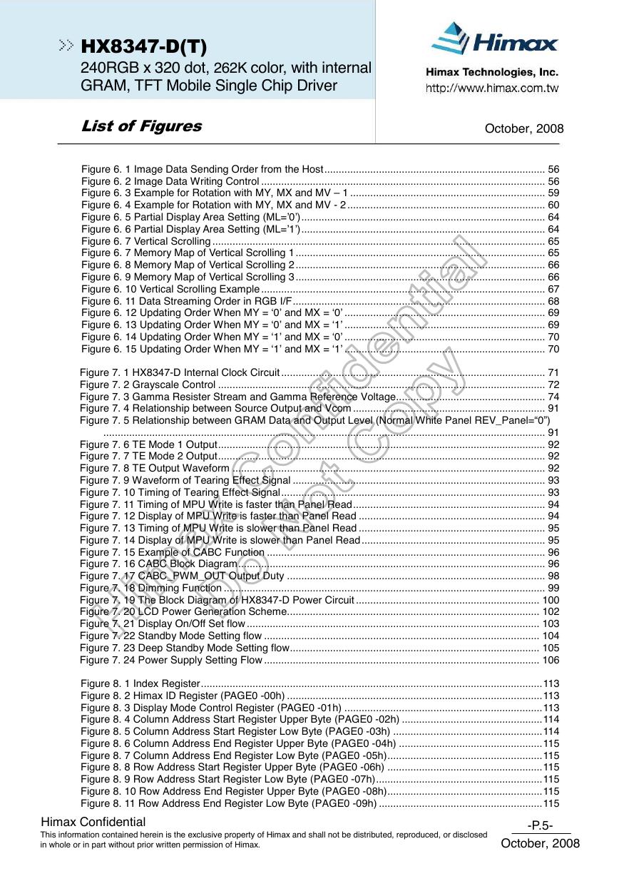
Figure 6. 1 Image Data Sending Order from the Host............................................................................. 56
Figure 6. 2 Image Data Writing Control ................................................................................................... 56
Figure 6. 3 Example for Rotation with MY, MX and MV – 1 .................................................................... 59
Figure 6. 4 Example for Rotation with MY, MX and MV - 2 ..................................................................... 60
Figure 6. 5 Partial Display Area Setting (ML=’0’)..................................................................................... 64
Figure 6. 6 Partial Display Area Setting (ML=’1’)..................................................................................... 64
Figure 6. 7 Vertical Scrolling .................................................................................................................... 65
Figure 6. 7 Memory Map of Vertical Scrolling 1....................................................................................... 65
Figure 6. 8 Memory Map of Vertical Scrolling 2....................................................................................... 66
Figure 6. 9 Memory Map of Vertical Scrolling 3....................................................................................... 66
Figure 6. 10 Vertical Scrolling Example ................................................................................................... 67
Figure 6. 11 Data Streaming Order in RGB I/F........................................................................................ 68
Figure 6. 12 Updating Order When MY = ‘0’ and MX = ‘0’ ...................................................................... 69
Figure 6. 13 Updating Order When MY = ‘0’ and MX = ‘1’ ...................................................................... 69
Figure 6. 14 Updating Order When MY = ‘1’ and MX = ‘0’ ...................................................................... 70
Figure 6. 15 Updating Order When MY = ‘1’ and MX = ‘1’ ...................................................................... 70
Figure 7. 1 HX8347-D Internal Clock Circuit ............................................................................................ 71
Figure 7. 2 Grayscale Control .................................................................................................................. 72
Figure 7. 3 Gamma Resister Stream and Gamma Reference Voltage.................................................... 74
Figure 7. 4 Relationship between Source Output and Vcom ................................................................... 91
Figure 7. 5 Relationship between GRAM Data and Output Level (Normal White Panel REV_Panel=“0”)
.......................................................................................................................................................... 91
Figure 7. 6 TE Mode 1 Output.................................................................................................................. 92
Figure 7. 7 TE Mode 2 Output.................................................................................................................. 92
Figure 7. 8 TE Output Waveform ............................................................................................................. 92
Figure 7. 9 Waveform of Tearing Effect Signal ........................................................................................ 93
Figure 7. 10 Timing of Tearing Effect Signal............................................................................................ 93
Figure 7. 11 Timing of MPU Write is faster than Panel Read................................................................... 94
Figure 7. 12 Display of MPU Write is faster than Panel Read ................................................................. 94
Figure 7. 13 Timing of MPU Write is slower than Panel Read ................................................................. 95
Figure 7. 14 Display of MPU Write is slower than Panel Read ................................................................ 95
Figure 7. 15 Example of CABC Function ................................................................................................. 96
Figure 7. 16 CABC Block Diagram........................................................................................................... 96
Figure 7. 17 CABC_PWM_OUT Output Duty .......................................................................................... 98
Figure 7. 18 Dimming Function ................................................................................................................ 99
Figure 7. 19 The Block Diagram of HX8347-D Power Circuit ................................................................ 100
Figure 7. 20 LCD Power Generation Scheme........................................................................................ 102
Figure 7. 21 Display On/Off Set flow ...................................................................................................... 103
Figure 7. 22 Standby Mode Setting flow ................................................................................................ 104
Figure 7. 23 Deep Standby Mode Setting flow....................................................................................... 105
Figure 7. 24 Power Supply Setting Flow ................................................................................................ 106
Figure 8. 1 Index Register.......................................................................................................................113
Figure 8. 2 Himax ID Register (PAGE0 -00h) .........................................................................................113
Figure 8. 3 Display Mode Control Register (PAGE0 -01h) .....................................................................113
Figure 8. 4 Column Address Start Register Upper Byte (PAGE0 -02h) .................................................114
Figure 8. 5 Column Address Start Register Low Byte (PAGE0 -03h) ....................................................114
Figure 8. 6 Column Address End Register Upper Byte (PAGE0 -04h) ..................................................115
Figure 8. 7 Column Address End Register Low Byte (PAGE0 -05h)......................................................115
Figure 8. 8 Row Address Start Register Upper Byte (PAGE0 -06h) ......................................................115
Figure 8. 9 Row Address Start Register Low Byte (PAGE0 -07h)..........................................................115
Figure 8. 10 Row Address End Register Upper Byte (PAGE0 -08h)......................................................115
Figure 8. 11 Row Address End Register Low Byte (PAGE0 -09h) .........................................................115
Himax Confidential
This information contained herein is the exclusive property of Himax and shall not be distributed, reproduced, or disclosed
in whole or in part without prior written permission of Himax.
-P.5-
October, 2008
�
October, 2008
HX8347-D(T)
240RGB x 320 dot, 262K color, with internal
GRAM, TFT Mobile Single Chip Driver
List of Figures
Figure 8. 12 Partial Area Start Row Register Upper Byte (PAGE0 -0Ah) ..............................................116
Figure 8. 13 Partial Area Start Row Register Low Byte (PAGE0 -0Bh)..................................................116
Figure 8. 14 Partial Area End Row Register Upper Byte (PAGE0 -0Ch) ...............................................116
Figure 8. 15 Partial Area End Row Register Low Byte (PAGE0 -0Dh)...................................................116
Figure 8. 16 Vertical Scroll Top Fixed Area Register Upper Byte (PAGE0 -0Eh) ..................................118
Figure 8. 17 Vertical Scroll Top Fixed Area Register Low Byte (PAGE0 -0Fh)......................................118
Figure 8. 18 Vertical Scroll Height Area Register Upper Byte (PAGE0 -10h) ........................................118
Figure 8. 19 Vertical Scroll Height Area Register Low Byte (PAGE0 -11h)............................................118
Figure 8. 20 Vertical Scroll Button Fixed Area Register Upper Byte (PAGE0 -12h) ..............................118
Figure 8. 21 Vertical Scroll Button Fixed Area Register Low Byte (PAGE0 -13h)..................................118
Figure 8. 22 Vertical Scroll Start Address Register Upper Byte (PAGE0 -14h)..................................... 120
Figure 8. 23 Vertical Scroll Start Address Register Low Byte (PAGE0 -15h)........................................ 120
Figure 8. 24 Memory Access Control Register (PAGE0 -16h) .............................................................. 121
Figure 8. 25 COLMOD Control Register (PAGE0 -17h) ........................................................................ 122
Figure 8. 26 OSC Control 1 Register (PAGE0 -18h) ............................................................................. 123
Figure 8. 27 OSC Control 2 Register (PAGE0 -19h) ............................................................................. 123
Figure 8. 28 Power Control 1 Register (PAGE0 -1Ah) .......................................................................... 124
Figure 8. 29 Power Control 2 Register (PAGE0 -1Bh) .......................................................................... 125
Figure 8. 30 Power Control 3 Register (PAGE0 -1Ch) .......................................................................... 126
Figure 8. 31 Power Control 4 Register (PAGE0 -1Dh) .......................................................................... 126
Figure 8. 32 Power Control 5 Register (PAGE0 -1Eh) .......................................................................... 127
Figure 8. 33 Power Control 6 Register (PAGE0 -1Fh)........................................................................... 127
Figure 8. 34 Read Data Register (PAGE0 -22h).................................................................................... 129
Figure 8. 35 Vcom Control 1 Register (PAGE0 -23h)............................................................................ 130
Figure 8. 36 Vcom Control 2 Register (PAGE0 -24h)............................................................................ 130
Figure 8. 37 Vcom Control 3 Register (PAGE0 -25h)............................................................................ 130
Figure 8. 38 Display Control 1 Register (PAGE0 -26h) ......................................................................... 132
Figure 8. 39 Display Control 2 Register (PAGE0 -27h) ......................................................................... 132
Figure 8. 40 Display Control 3 Register (PAGE0 -28h) ......................................................................... 132
Figure 8. 41 Frame Control 1 Register (PAGE0 -29h)........................................................................... 135
Figure 8. 42 Frame Control 2 Register (PAGE0 -2Ah) .......................................................................... 135
Figure 8. 43 Frame Control 3 Register (PAGE0 -2Bh) .......................................................................... 135
Figure 8. 44 Frame Control 4 Register (PAGE0 -2Ch) .......................................................................... 135
Figure 8. 45 Cycle Control Register 1 (PAGE0 -2Dh) ........................................................................... 137
Figure 8. 46 Cycle Control Register 2 (PAGE0 -2Eh)............................................................................ 137
Figure 8. 47 Cycle Control Register (PAGE0 -2Fh)............................................................................... 138
Figure 8. 48 RGB Interface Control Register (PAGE0 -31h) ................................................................. 139
Figure 8. 49 RGB Interface Control Register (PAGE0 -32h) ................................................................. 139
Figure 8. 50 RGB Interface Control Register (PAGE0 -33h) ................................................................. 139
Figure 8. 51 RGB Interface Control Register (PAGE0 -34h) ................................................................. 139
Figure 8. 52 Panel Characteristic Control Register (PAGE0 -36h)........................................................ 141
Figure 8. 53 OTP Command 1 (PAGE0 -38h) ....................................................................................... 142
Figure 8. 54 OTP Command 2 (PAGE0 -39h) ....................................................................................... 142
Figure 8. 55 OTP Command 3 (PAGE0 -3Ah)....................................................................................... 142
Figure 8. 56 CABC Control 1 Register (PAGE0 -3Ch)........................................................................... 143
Figure 8. 57 CABC Control 2 Register (PAGE0 -3Dh)........................................................................... 143
Figure 8. 58 CABC Control 3 Register (PAGE0 -3Eh)........................................................................... 143
Figure 8. 59 CABC Control 4 Register (PAGE0 -3Fh) ........................................................................... 143
Figure 8. 60 Gamma Control 1 Register (PAGE0 -40h) ........................................................................ 145
Figure 8. 61 Gamma Control 2 Register (PAGE0 -41h) ........................................................................ 145
Figure 8. 62 Gamma Control 3 Register (PAGE0 -42h) ........................................................................ 145
Figure 8. 63 Gamma Control 4 Register (PAGE0 -43h) ........................................................................ 145
Figure 8. 64 Gamma Control 5 Register (PAGE0 -44h) ........................................................................ 145
Figure 8. 65 Gamma Control 6 Register (PAGE0 -45h) ........................................................................ 145
Figure 8. 66 Gamma Control 7 Register (PAGE0 -46h) ........................................................................ 146
Himax Confidential
This information contained herein is the exclusive property of Himax and shall not be distributed, reproduced, or disclosed
in whole or in part without prior written permission of Himax.
-P.6-
October, 2008
�
October, 2008
HX8347-D(T)
240RGB x 320 dot, 262K color, with internal
GRAM, TFT Mobile Single Chip Driver
List of Figures
Figure 8. 67 Gamma Control 8 Register (PAGE0 -47h) ........................................................................ 146
Figure 8. 68 Gamma Control 9 Register (PAGE0 -48h) ........................................................................ 146
Figure 8. 69 Gamma Control 10 Register (PAGE0 -49h) ...................................................................... 146
Figure 8. 70 Gamma Control 11 Register (PAGE0 -4Ah) ...................................................................... 146
Figure 8. 71 Gamma Control 12 Register (PAGE0 -4Bh) ...................................................................... 146
Figure 8. 72 Gamma Control 13 Register (PAGE0 -4Ch)...................................................................... 147
Figure 8. 73Gamma Control 14 Register (PAGE0 -50h) ....................................................................... 147
Figure 8. 74 Gamma Control 15 Register (PAGE0 -51h) ...................................................................... 147
Figure 8. 75 Gamma Control 16 Register (PAGE0 -52h) ...................................................................... 147
Figure 8. 76 Gamma Control 17 Register (PAGE0 -53h) ...................................................................... 147
Figure 8. 77 Gamma Control 18 Register (PAGE0 -54h) ...................................................................... 147
Figure 8. 78 Gamma Control 19 Register (PAGE0 -55h) ...................................................................... 148
Figure 8. 79 Gamma Control 20 Register (PAGE0 -56h) ...................................................................... 148
Figure 8. 80 Gamma Control 21 Register (PAGE0 -57h) ...................................................................... 148
Figure 8. 81 gamma Control 22 Register (PAGE0 -58h) ....................................................................... 148
Figure 8. 82 Gamma Control 23 Register (PAGE0 -59h) ...................................................................... 148
Figure 8. 83 Gamma Control 24 Register (PAGE0 -5Ah) ...................................................................... 148
Figure 8. 84 Gamma Control 25 Register (PAGE0 -5Bh) ...................................................................... 149
Figure 8. 85 Gamma Control 26 Register (PAGE0 -5Ch)...................................................................... 149
Figure 8. 86 Gamma Control 27 Register (PAGE0 -5Dh)...................................................................... 149
Figure 8. 87 Gamma Control 28 Register (PAGE0 -5Eh) ...................................................................... 149
Figure 8. 88 Mode Control Register (PAGE0 -60h) ............................................................................... 150
Figure 8. 89 Power Saving Internal Control Register (R68h) ................................................................ 150
Figure 8. 90 Power Saving Internal Control Register (R69h) ................................................................ 150
Figure 8. 91 Power Saving Internal Control Register (R70h) ................................................................ 150
Figure 8. 92 Power Saving Internal Control Register (R71h) ................................................................ 151
Figure 8. 93 Source OP Control Register (PAGE0 -RE8h) ................................................................... 151
Figure 8. 94 Source OP Control Register (PAGE0 -RE9h) ................................................................... 151
Figure 8. 95 Power Control Internal used (1) Register (PAGE0 -REAh) ............................................... 152
Figure 8. 96 Power Control Internal used (2) Register (PAGE0 -REBh) ............................................... 152
Figure 8. 97 Source Control Internal used (1) Register (PAGE0 -RECh).............................................. 152
Figure 8. 98 Source Control Internal used (2) Register (PAGE0 -REDh).............................................. 152
Figure 8. 99 Command Page select Register (RFFh) ........................................................................... 152
Figure 8. 100 CABC control 5 (PAGE1 – RC3h).................................................................................... 153
Figure 8. 101 CABC control 6 (PAGE1 – RC5h).................................................................................... 153
Figure 8. 102 CABC control 7 (PAGE1 – RC7h).................................................................................... 153
Figure 8. 103 Gain select register 0 (PAGE1 – RCBh).......................................................................... 154
Figure 8. 104 Gain select register 1 (PAGE1 – RCCh).......................................................................... 154
Figure 8. 105 Gain select register 2 (PAGE1 – RCDh).......................................................................... 154
Figure 8. 106 Gain select register 3 (PAGE1 – RCEh).......................................................................... 154
Figure 8. 107 Gain select register 4 (PAGE1 – RCFh) .......................................................................... 154
Figure 8. 108 Gain select register 5 (PAGE1 – RD0h) .......................................................................... 154
Figure 8. 109 Gain select register 6 (PAGE1 – RD1h) .......................................................................... 154
Figure 8. 110 Gain select register 7 (PAGE1 – RD2h)........................................................................... 155
Figure 8. 111 Gain select register 8 (PAGE1 – RD3h)........................................................................... 155
Figure 9. 1 Layout Recommendation of HX8347-D MPU Mode............................................................ 156
Figure 9. 2 Layout Recommendation of HX8347-D (SPI+RGB)............................................................ 157
Figure 11. 1 Parallel Interface Characteristics (8080-Series MPU) ....................................................... 165
Figure 11. 2 Chip Select Timing............................................................................................................. 166
Figure 11. 3 Write to Read and Read to Write Timing ........................................................................... 166
Figure 11. 4 Serial Interface Characteristics .......................................................................................... 167
Figure 11. 5 Reset Input Timing............................................................................................................. 170
Himax Confidential
This information contained herein is the exclusive property of Himax and shall not be distributed, reproduced, or disclosed
in whole or in part without prior written permission of Himax.
-P.7-
October, 2008
�



 V2版本原理图(Capacitive-Fingerprint-Reader-Schematic_V2).pdf
 摄像头工作原理.doc
 VL53L0X简要说明(En.FLVL53L00216).pdf
 原理图(DVK720-Schematic).pdf
 原理图(Pico-Clock-Green-Schdoc).pdf
 原理图(RS485-CAN-HAT-B-schematic).pdf
 File:SIM7500_SIM7600_SIM7800 Series_SSL_Application Note_V2.00.pdf
 ADS1263(Ads1262).pdf
 原理图(Open429Z-D-Schematic).pdf
 用户手册(Capacitive_Fingerprint_Reader_User_Manual_CN).pdf
 CY7C68013A(英文版)(CY7C68013A).pdf
 TechnicalReference_Dem.pdf