Product Specification
Part Name: OLED Display Module
Part ID: UG-9664HDDAG01
Doc No.: SAS1-6017-B
Customer:
Approved by
Notes:
From: Univision Technology Inc.
Approved by
2006, 11, 09
UUnniivviissiioonn TTeecchhnnoollooggyy IInncc..
8, Kebei RD 2, Science Park, Chu-Nan, Taiwan 350, R.O.C.
1. Please contact Univision Technology Inc. before assigning your product based on this
module specification
2. The information contained herein is presented merely to indicate the characteristics and
performance of our products. No responsibility is assumed by Univision Technology
Inc. for any intellectual property claims or other problems that may result from
application based on the module described herein.
�
RReevviisseedd HHiissttoorryy
UUnniivviissiioonn TTeecchhnnoollooggyy IInncc..
Doc. No: SAS1-6017-B
Part Number
Revision
Revision Content
UG-9664HDDAG01
A
UG-9664HDDAG01
B
New
1. Section3.3………...….Page 11
Update C.I.E Spec
2. Section4.2.1.…..….....Page 12
Update step 3 Driver IC initial
Setting.
3. Section8.1.……...…...Page 21
Update handling precaution 6.
Revised on
June 26, 2006
October 20,2006
i
�
UUnniivviissiioonn TTeecchhnnoollooggyy IInncc..
Doc. No: SAS1-6017-B
NNoottiiccee::
No part of this material may be reproduces or duplicated in any form or by any means
without the written permission of Univision Technology Inc. Univision Technology Inc.
reserves the right to make changes to this material without notice. Univision Technology
Inc. does not assume any liability of any kind arising out of any inaccuracies contained in this
material or due to its application or use in any product or circuit and, further, there is no
representation that this material is applicable to products requiring high level reliability, such
as, medical products. Moreover, no license to any intellectual property rights is granted by
implication or otherwise, and there is no representation or warranty that anything made in
accordance with this material will be free from any patent or copyright infringement of a
third party. This material or portions thereof may contain technology or the subject relating
to strategic products under the control of Foreign Exchange and Foreign Trade Law of
Taiwan and may require an export license from the Ministry of International Trade and
Industry or other approval from another government agency.
© Univision Technology Inc. 2006, All rights reserved.
All other product names mentioned herein are trademarks and/or registered trademarks of
their respective companies.
ii
�
UUnniivviissiioonn TTeecchhnnoollooggyy IInncc..
Doc. No: SAS1-6017-B
CCoonntteennttss
RReevviissiioonn HHiissttoorryy ................................................................................................... i
NNoottiiccee ................................................................................................................... ii
CCoonntteennttss .............................................................................................................. iii
11.. BBaassiicc SSppeecciiffiiccaattiioonnss .................................................................................. 1~5
1.1 Display Specifications .................................................................................................1
1.2 Mechanical Specifications ...........................................................................................1
1.3 Active Area & Pixel Construction ...............................................................................1
1.4 Mechanical Drawing....................................................................................................2
1.5 Pin Definition...............................................................................................................3
1.6 Block Diagram.............................................................................................................5
22.. AAbbssoolluuttee MMaaxxiimmuumm RRaattiinnggss .......................................................................... 6
33.. EElleeccttrriiccaall CChhaarraacctteerriissttiiccss......................................................................... 7~11
3.1 DC Characteristics .......................................................................................................7
3.2 AC Characteristics .......................................................................................................8
3.2.1 68XX-Series MPU Parallel Interface Timing Characteristics...........................8
3.2.2 80XX-Series MPU Parallel Interface Timing Characteristics...........................9
3.2.3 Serial Interface Timing Characteristics ...........................................................10
3.3 Optics & Electrical Characteristics............................................................................11
3.4 General Electrical Specification ................................................................................11
44.. FFuunnccttiioonnaall SSppeecciiffiiccaattiioonn ....................................................................... 12~14
4.1 Commands .................................................................................................................12
4.2 Power down and Power up Sequence ........................................................................12
4.2.1 Power up Sequence..........................................................................................12
4.2.2 Power down Sequence .....................................................................................12
4.3 Reset Circuit...............................................................................................................12
4.4 Actual Application Example......................................................................................13
55.. RReelliiaabbiilliittyy...................................................................................................... 15
5.1 Contents of Reliability Tests......................................................................................15
5.2 Lifetime......................................................................................................................15
5.3 Failure Check Standard..............................................................................................15
66.. OOuuttggooiinngg QQuuaalliittyy CCoonnttrrooll SSppeecciiffiiccaattiioonnss.............................................. 16~19
6.1 Environment Required...............................................................................................16
6.2 Sampling Plan ............................................................................................................16
6.3 Criteria & Acceptable Quality Level .........................................................................16
6.3.1 Cosmetic Check (Display Off) in Non-Active Area........................................16
6.3.2 Cosmetic Check (Display Off) in Active Area.................................................18
6.3.3 Pattern Check (Display On) in Active Area.....................................................19
77.. PPaacckkaaggee SSppeecciiffiiccaattiioonnss ................................................................................ 20
iii
�
UUnniivviissiioonn TTeecchhnnoollooggyy IInncc..
Doc. No: SAS1-6017-B
88.. PPrreeccaauuttiioonnss WWhheenn UUssiinngg TThheessee OOEELL DDiissppllaayy MMoodduulleess....................... 21~23
8.1 Handling Precautions.................................................................................................21
8.2 Storage Precautions....................................................................................................22
8.3 Designing Precautions ...............................................................................................22
8.4 Precautions when disposing of the OEL display modules.........................................23
8.5 Other Precautions.......................................................................................................23
99.. AAppppeennddiixxeess ................................................................................................... 24
9.1 Software Initial Setting ..............................................................................................24
iv
�
UUnniivviissiioonn TTeecchhnnoollooggyy IInncc..
Doc. No: SAS1-6017-B
11.. BBaassiicc SSppeecciiffiiccaattiioonnss
1.1 Display Specifications
1) Display Mode:
2) Display Color:
3) Drive Duty:
Passive Matrix
65,536 Colors (Maximum)
1/64 Duty
1.2 Mechanical Specifications
1) Outline Drawing: According to the annexed outline drawing number
2) Number of Pixels: 96 (RGB) × 64
3) Panel Size:
4) Active Area:
5) Pixel Pitch:
6) Pixel Size:
7) Weight:
25.70 × 22.20 × 1.50 (mm)
20.14 × 13.42 (mm)
0.07 × 0.21 (mm)
0.05 × 0.19 (mm)
1.8 (g)
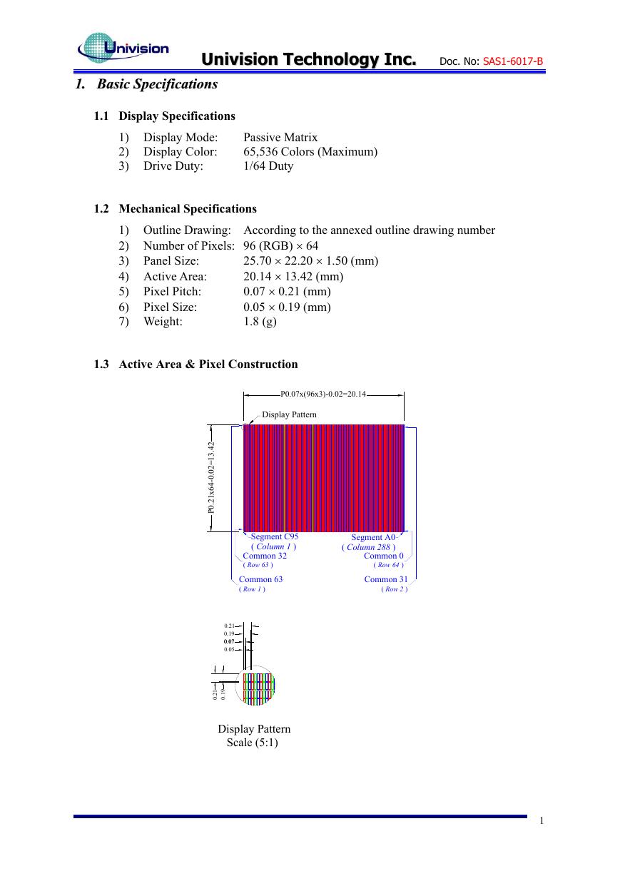
1.3 Active Area & Pixel Construction
P0.07x(96x3)-0.02=20.14
Display Pattern
Segment C95
( Column 1 )
Common 32
( Row 63 )
Common 63
( Row 1 )
Segment A0
( Column 288 )
Common 0
( Row 64 )
Common 31
( Row 2 )
2
4
.
.
3
1
=
2
0
0
-
4
6
x
1
2
.
0
P
0.21
0.19
0.07
0.07
0.05
1
2
.
0
9
1
.
0
Display Pattern
Scale (5:1)
1
�
UUnniivviissiioonn TTeecchhnnoollooggyy IInncc..
Doc. No: SAS1-6017-B
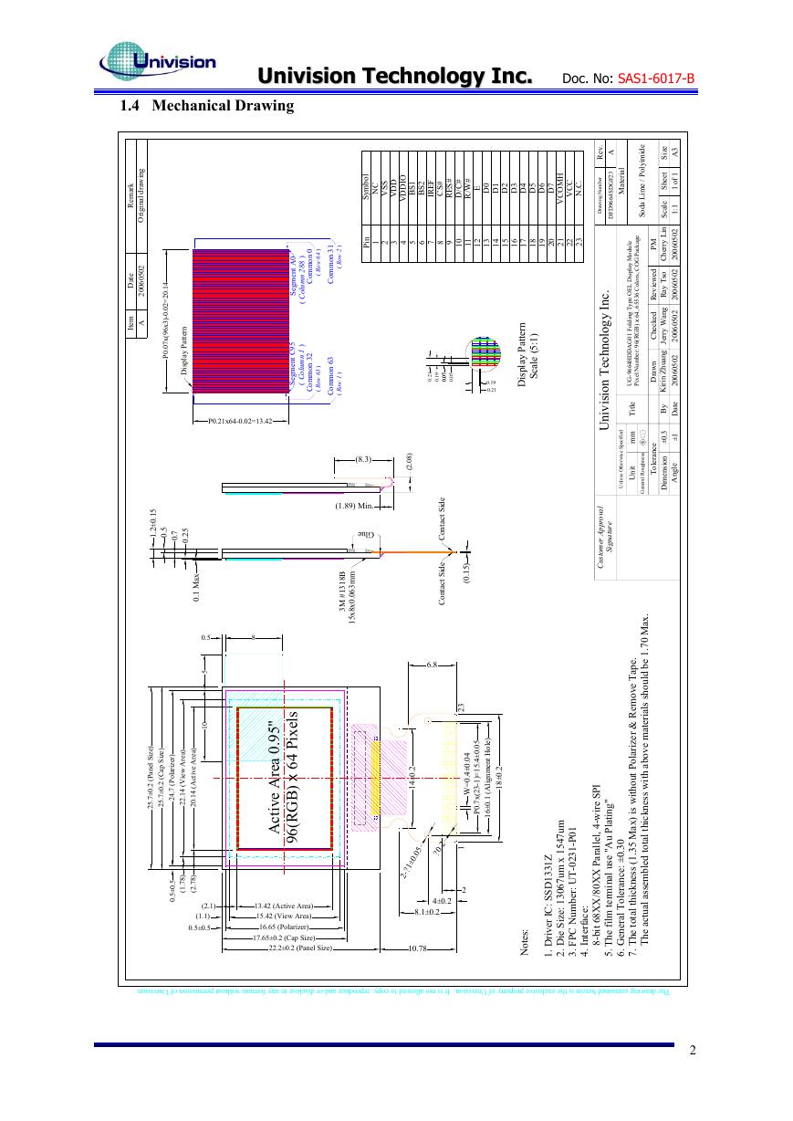
1.4 Mechanical Drawing
k
r
a
m
e
R
g
n
i
w
a
r
d
l
a
n
i
g
i
r
O
e
t
a
D
2
0
5
0
6
0
0
2
m
e
t
I
A
.
4
1
0
2
=
2
0
.
0
-
)
3
x
6
9
(
x
7
0
.
0
P
n
r
e
t
t
a
P
y
a
l
p
s
i
D
P0.21x64-0.02=13.42
l
o
b
m
y
S
C
N
S
S
V
D
D
V
I
O
D
D
V
1
S
B
2
S
B
F
E
R
I
#
S
C
#
S
E
R
#
C
D
/
#
W
R
/
E
0
D
1
D
2
D
3
D
4
D
5
D
6
D
7
D
H
M
O
C
V
C
C
V
.
.
C
N
n
i
P
2 5 76431
8
09
1
1
1
2
1
3
1
4
1
5
1
6
1
7
1
8
1
9
1
0
2
1
2
2
2
3
2
)
2
w
o
R
(
1
3
n
o
m
m
o
C
0
)
4
6
w
o
R
(
n
o
m
m
o
C
0
A
t
n
e
m
g
e
S
)
8
8
2
n
m
u
l
o
C
(
n
r
e
t
t
a
P
y
a
l
p
s
i
D
)
1
:
5
(
e
l
a
c
S
1
2
0
.
9
1
0
.
7
7
0
0
0
0
.
.
5
0
0
.
0.19
0.21
3
6
n
o
m
m
o
C
)
1
w
o
R
(
5
9
C
t
n
e
m
g
e
S
)
1
n
m
u
l
o
C
(
2
3
n
o
m
m
o
C
)
3
6
w
o
R
(
(8.3)
)
8
0
.
2
(
(1.89) Min.
Glue
B
8
1
3
1
#
M
3
m
m
3
6
0
0
x
8
x
5
1
.
NC
VCC
VCOMH
VSS
D15
D14
D13
D12
D11
D10
D9
D8
D7
D6
D5
D4
D3
D2
D1
D0
E
R/W
D/C
RES#
CS#
IREF
VDDIO
BS3
VSS
BS2
VDDIO
BS1
VSS
BS0
VDDIO
VDD
VBREF
FB
VDDB
GDR
VSSB
VSS
NC
2
.
0
±
4
1
e
d
i
S
t
c
a
t
n
o
C
e
d
i
S
t
c
a
t
n
o
C
6.8
)
5
1
0
(
.
3
2
5
0
4
0
.
0
±
4
.
0
=
W
.
0
±
4
.
5
1
=
)
1
-
3
2
(
x
7
.
0
P
2-?1±0.05 ?0.2
4±0.2
8.1±0.2
1
2
.
5
1
0
±
2
.
1
5
0
.
7
.
0
5
2
.
0
x
a
M
1
.
0
0.5
5
0
1
)
a
e
r
A
w
e
i
V
(
4
1
.
2
2
)
a
e
r
A
e
v
i
t
c
A
(
4
1
.
0
2
)
8
7
.
1
(
)
8
7
.
2
(
(2.1)
(1.1)
0.5±0.5
)
r
e
z
i
r
a
l
o
P
(
.
7
4
2
.
5
0
±
5
0
.
)
e
z
i
S
p
a
C
(
2
.
0
±
7
5
2
.
)
e
z
i
S
l
e
n
a
P
(
2
.
0
±
7
5
2
.
8
.
"
5
9
0
a
e
r
A
e
v
i
t
c
A
s
l
e
x
i
P
4
6
x
)
B
G
R
(
6
9
13.42 (Active Area)
15.42 (View Area)
16.65 (Polarizer)
17.65±0.2 (Cap Size)
22.2±0.2 (Panel Size)
10.78
)
e
l
o
H
t
n
e
m
n
g
i
l
A
(
1
.
0
±
6
1
2
.
0
±
8
1
:
s
e
t
o
N
.
v
e
R
A
r
e
b
m
u
N
g
n
i
w
a
r
D
3
2
F
G
D
S
4
6
6
9
D
F
D
l
a
i
r
e
t
a
M
e
d
i
m
i
y
l
o
P
i
/
e
m
L
a
d
o
S
e
z
i
S
3
A
t
e
e
h
S
1
f
o
1
e
l
a
c
S
1
:
1
.
c
n
I
y
g
o
l
o
n
h
c
e
T
n
o
i
s
i
v
i
n
U
l
a
v
o
r
p
p
A
r
e
m
o
t
s
u
C
e
r
u
t
a
n
g
i
S
e
g
a
k
c
a
P
G
O
C
,
s
r
o
l
o
C
6
3
5
5
6
,
4
6
x
)
B
G
R
(
6
9
:
r
e
b
m
u
N
l
e
x
i
P
e
l
u
d
o
M
y
a
l
p
s
i
D
L
E
O
e
p
y
T
g
n
i
d
l
o
F
1
0
G
A
D
D
H
4
6
6
9
-
G
U
M
P
n
i
L
y
r
r
e
h
C
d
e
w
e
i
v
e
R
o
s
T
y
a
R
d
e
k
c
e
h
C
g
n
a
W
y
r
r
e
J
n
w
a
r
D
g
n
a
u
h
Z
n
i
r
i
K
2
0
5
0
6
0
0
2
2
0
5
0
6
0
0
2
2
0
5
0
6
0
0
2
2
0
5
0
6
0
0
2
e
l
t
i
T
m
m
t
i
n
U
d
e
i
f
i
c
e
p
S
e
s
i
w
r
e
h
t
O
s
s
e
l
n
U
y
B
e
t
a
D
3
.
0
±
1
±
n
o
i
s
n
e
m
D
i
e
l
g
n
A
e
c
n
a
r
e
l
o
T
s
s
e
n
h
g
u
o
R
l
a
r
e
n
e
G
.
x
a
M
0
7
.
1
e
b
d
l
u
o
h
s
s
l
a
i
r
e
t
a
m
e
v
o
b
a
.
e
p
a
T
e
v
o
m
e
R
&
r
e
z
i
r
a
l
o
P
t
u
o
h
t
i
w
s
i
)
x
a
M
5
3
.
h
t
i
w
s
s
e
n
k
c
i
h
t
l
a
t
o
t
1
(
s
s
e
n
k
c
i
h
t
l
a
t
o
t
e
h
T
d
e
l
b
m
e
s
s
a
l
a
u
t
c
a
e
h
T
.
7
3
4
.
5
.
6
I
P
S
e
r
i
w
-
4
,
l
e
l
l
a
r
a
P
X
X
0
8
/
X
X
8
6
t
i
b
-
8
"
g
n
i
t
a
l
P
u
A
"
e
s
u
l
a
n
i
m
r
e
t
.
0
3
0
±
:
e
c
n
a
r
e
l
o
T
m
l
i
f
e
h
T
l
a
r
e
n
e
G
m
u
7
4
5
1
x
m
u
7
6
0
3
1
:
e
z
i
S
e
i
D
.
2
1
0
P
-
1
3
2
0
-
T
U
:
r
e
b
m
u
N
C
P
F
.
Z
1
3
3
1
D
S
S
:
C
I
r
e
v
i
r
D
.
1
:
e
c
a
f
r
e
t
n
I
.
The drawing contained herein is the exclusive property of Univision. It is not allowed to copy, reproduce and or disclose in any formats without permission of Univision.
2
�
UUnniivviissiioonn TTeecchhnnoollooggyy IInncc..
Doc. No: SAS1-6017-B
1.5 Pin Definition
Pin Number
PPoowweerr SSuuppppllyy PPiinnss
Symbol Type
2
3
4
VSS
VDD
VDDIO
22
VCC
MMPPUU IInntteerrffaaccee PPiinnss
8
9
CS#
RES#
10
D/C#
P
P
P
P
I
I
I
11
R/W# (WR#)
I
12
E (RD#)
I
13~20
D0~D7
I/O
Function
GGrroouunndd ooff OOEELL SSyysstteemm
This is a ground pin. It also acts as a reference for the
logic pins, the OEL driving voltages, and the analog
circuits. It must be connected to external ground.
PPoowweerr SSuuppppllyy PPiinnss ffoorr CCoorree VVDDDD
This is a voltage supply pin. It must be connected to
external source.
PPoowweerr SSuuppppllyy ffoorr IInntteerrffaaccee LLooggiicc LLeevveell
It should be match with the MCU interface voltage level.
VDDIO must always be equal or lower than VDD.
PPoowweerr SSuuppppllyy ffoorr OOEELL PPaanneell
This is the most positive voltage supply pin of the chip.
It should be supplied externally.
to
the command register.
CChhiipp SSeelleecctt
This pin is the chip select input. The chip is enabled for
MCU communication only when CS# is pulled low.
PPoowweerr RReesseett ffoorr CCoonnttrroolllleerr aanndd DDrriivveerr
This pin is reset signal input. When the pin is low,
initialization of the chip is executed.
DDaattaa//CCoommmmaanndd CCoonnttrrooll
This pin is Data/Command control pin. When the pin is
pulled high, the input at D0~D7 is treated as display data.
When the pin is pulled low, the input at D0~D7 will be
transferred
For detail
relationship to MCU interface signals, please refer to the
Timing Characteristics Diagrams.
RReeaadd//WWrriittee SSeelleecctt oorr WWrriittee
This pin is MCU interface input. When interfacing to a
68XX-series microprocessor, this pin will be used as
Read/Write (R/W#) selection input. Pull this pin to
“High” for read mode and pull it to “Low” for write
mode.
When 80XX interface mode is selected, this pin will be
the Write (WR#) input. Data write operation is initiated
when this pin is pulled low and the CS# is pulled low.
RReeaadd//WWrriittee EEnnaabbllee oorr RReeaadd
This pin is MCU interface input. When interfacing to a
68XX-series microprocessor, this pin will be used as the
Enable (E) signal. Read/write operation is initiated when
this pin is pulled high and the CS# is pulled low.
When connecting to an 80XX-microprocessor, this pin
receives the Read (RD#) signal. Data read operation is
initiated when this pin is pulled low and CS# is pulled
low.
HHoosstt DDaattaa IInnppuutt//OOuuttppuutt BBuuss
These pins are 8-bit bi-directional data bus to be
connected to the microprocessor’s data bus. When serial
mode is selected, D1 will be the serial data input SDIN
and D0 will be the serial clock input SCLK.
3
�




 V2版本原理图(Capacitive-Fingerprint-Reader-Schematic_V2).pdf
 摄像头工作原理.doc
 VL53L0X简要说明(En.FLVL53L00216).pdf
 原理图(DVK720-Schematic).pdf
 原理图(Pico-Clock-Green-Schdoc).pdf
 原理图(RS485-CAN-HAT-B-schematic).pdf
 File:SIM7500_SIM7600_SIM7800 Series_SSL_Application Note_V2.00.pdf
 ADS1263(Ads1262).pdf
 原理图(Open429Z-D-Schematic).pdf
 用户手册(Capacitive_Fingerprint_Reader_User_Manual_CN).pdf
 CY7C68013A(英文版)(CY7C68013A).pdf
 TechnicalReference_Dem.pdf