VS1003b
VS1003
VS1003 - MP3/WMA AUDIO CODEC
Features
Description
or line input
• Decodes MPEG 1 & 2 audio layer III (CBR
+VBR +ABR); WMA 4.0/4.1/7/8/9 all pro-
files (5-384kbit/s); WAV (PCM + IMA AD-
PCM); General MIDI / SP-MIDI files
• Encodes IMA ADPCM from microphone
• Streaming support for MP3 and WAV
• Bass and treble controls
• Operates with a single 12..13 MHz clock
• Internal PLL clock multiplier
• Low-power operation
• High-quality on-chip stereo DAC with no
• Stereo earphone driver capable of driving a
• Separate operating voltages for analog, dig-
• 5.5 KiB On-chip RAM for user code / data
• Serial control and data interfaces
• Can be used as a slave co-processor
• SPI flash boot for special applications
• UART for debugging purposes
• New functions may be added with software
phase error between channels
30Ω load
ital and I/O
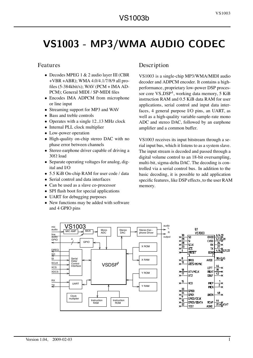
VS1003 is a single-chip MP3/WMA/MIDI audio
decoder and ADPCM encoder. It contains a high-
performance, proprietary low-power DSP proces-
sor core VS DSP4, working data memory, 5 KiB
instruction RAM and 0.5 KiB data RAM for user
applications, serial control and input data inter-
faces, 4 general purpose I/O pins, an UART, as
well as a high-quality variable-sample-rate mono
ADC and stereo DAC, followed by an earphone
amplifier and a common buffer.
VS1003 receives its input bitstream through a se-
rial input bus, which it listens to as a system slave.
The input stream is decoded and passed through a
digital volume control to an 18-bit oversampling,
multi-bit, sigma-delta DAC. The decoding is con-
trolled via a serial control bus. In addition to the
basic decoding, it is possible to add application
specific features, like DSP effects, to the user RAM
memory.
and 4 GPIO pins
Version 1.04,
2009-02-03
1
VLSISolutionyInstruction RAMInstruction ROMStereo DACMonoADCLRUARTSerialData/ControlInterfaceStereo Ear−phone DriverDREQSOSISCLKXCSRXTXaudiooutputX ROMX RAMY ROMY RAM4GPIOGPIOVSDSP4XDCSVS1003MIC AMP ClockmultiplierMUXlineaudiomicaudio�
VS1003b
VS1003
CONTENTS
Contents
1 Licenses
2 Disclaimer
3 Definitions
4 Characteristics & Specifications
9
9
9
10
4.1 Absolute Maximum Ratings
.
. . . .
.
. . . .
.
. . . . . .
. . . . . .
. . . . .
. . . .
10
4.2 Recommended Operating Conditions . . .
. .
. . . . . .
. . . . .
. . . . . .
. . . . .
.
10
4.3 Analog Characteristics
. . . .
4.4 Power Consumption . . . . . .
.
.
. . . .
. . . .
.
.
. . . .
. . . .
.
.
. . . . .
. . . . . .
. . . . .
. . . .
11
. . . . .
. . . . . .
. . . . .
. . . .
12
4.5 Digital Characteristics
. . . . .
.
. . . .
. .
. . . . . .
. . . . .
. . . . . .
. . . . .
4.6 Switching Characteristics - Boot Initialization . . . . . .
. . . . .
. . . . . .
. . . . .
.
.
12
12
4.7 Typical characteristics . . . . .
. . . .
.
. . . .
.
. . . . . .
. . . . . .
. . . . .
. . . .
13
4.7.1 Line input ADC . . .
.
. . . .
. .
. . . .
.
. . .
. . .
. . .
. .
. . .
. . .
. .
13
4.7.2 Microphone input ADC . .
.
. . . .
.
. . . .
. .
. . .
. . . . .
. . .
. . .
. .
13
4.7.3 RIGHT and LEFT outputs . .
.
. . . .
. .
. . . .
. . .
. . . . .
. . .
. . .
. .
14
5 Packages and Pin Descriptions
15
5.1 Packages
.
. . . . . . . . . .
. . . .
.
. . . .
.
. . . . . .
. . . . . .
. . . . .
. . . .
15
5.1.1 LQFP-48 . . . . . . .
5.1.2 BGA-49 . . . . . . . .
.
.
. . . .
. .
. . . .
. . . .
. .
. . . .
.
.
. . .
. . .
. . .
. .
. . .
. . .
. .
15
. . .
. . .
. . .
. .
. . .
. . .
. .
15
5.2 LQFP-48 and BGA-49 Pin Descriptions . . . .
.
. . . . . .
. . . . . .
. . . . .
. . . .
16
6 Connection Diagram, LQFP-48
Version 1.04,
2009-02-03
18
2
VLSISolutiony�
VS1003b
VS1003
CONTENTS
19
7 SPI Buses
7.1 General
. . . .
. . .
. .
. . .
. .
. . .
. . .
. .
. . . .
. .
. . .
. . .
. . .
. .
. . . .
19
7.2 SPI Bus Pin Descriptions . . .
. .
. . .
. . .
. .
. . . .
. .
. . .
. . .
. . .
. .
. . .
.
19
7.2.1 VS1002 Native Modes (New Mode) . .
. .
. . . .
. . . . . .
. . . . .
. . . . .
19
7.2.2 VS1001 Compatibility Mode . .
. .
. . . .
.
. . . . . .
. . . . . .
. . . . .
. .
19
7.3 Data Request Pin DREQ .
. . .
. . .
. .
. . .
. .
. . .
. .
. . .
. . .
. . .
. .
. . . .
20
7.4 Serial Protocol for Serial Data Interface (SDI) .
. .
. . .
. .
. . .
. . .
. . .
. .
. . .
.
20
7.4.1 General
. . .
. . . . .
. . . .
.
. . . .
. .
. . . .
. . . . . .
. . . . .
. . . . .
20
7.4.2
SDI in VS1002 Native Modes (New Mode) .
.
. . . . .
. . . . . .
. . . . .
. .
20
7.4.3
SDI in VS1001 Compatibility Mode . . . .
7.4.4
Passive SDI Mode . .
.
. . . .
. .
. . . .
.
.
. . . . . .
. . . . . .
. . . . .
. .
21
. . . . . .
. . . . .
. . . . . .
. .
21
7.5 Serial Protocol for Serial Command Interface (SCI) . . .
. .
. . .
. . .
. . .
. .
. . .
.
21
7.5.1 General
. . .
. . . . .
. . . .
7.5.2
SCI Read . .
. . . . .
. . . .
7.5.3
SCI Write . . . . . .
.
. . . .
.
.
.
. . . .
. .
. . . .
. . . . . .
. . . . .
. . . . .
21
. . . .
. .
. . . .
. . . . . .
. . . . .
. . . . .
22
. . . .
. .
. . . .
. . . . . .
. . . . .
. . . . .
22
7.6 SPI Timing Diagram . . .
. . .
. . .
. .
. . .
. .
. . .
. .
. . .
. . .
. . .
. .
. . . .
23
7.7 SPI Examples with SM SDINEW and SM SDISHARED set
.
. .
. . .
.
. . . .
. .
. .
24
7.7.1 Two SCI Writes . . .
.
. . . .
.
. . . .
. .
. . . .
. . .
. . . . .
. . .
. . .
. .
24
7.7.2 Two SDI Bytes . . . .
.
. . . .
. .
. . . .
.
. . .
. . .
. . .
. .
. . .
. . .
. .
24
7.7.3
SCI Operation in Middle of Two SDI Bytes . . . .
. . .
. . .
. . .
. .
. . .
. .
25
8 Functional Description
26
8.1 Main Features . . . . . . . . .
.
. . . .
.
. . . .
.
. . . . .
. . . . . .
. . . . .
. . . .
26
8.2 Supported Audio Codecs . . . .
.
. . . .
. .
. . . . . .
. . . . .
. . . . . .
. . . . .
.
26
8.2.1
Supported MP3 (MPEG layer III) Formats
.
. . .
. . .
. . .
. . .
. .
. . . . .
26
Version 1.04,
2009-02-03
3
VLSISolutiony�
VS1003b
VS1003
CONTENTS
8.2.2
Supported WMA Formats
.
. . . .
.
. . . .
.
. . . . .
. . .
. . . . .
. . .
. .
27
8.2.3
Supported RIFF WAV Formats .
. .
. . . .
8.2.4
Supported MIDI Formats . . . .
. .
. . . .
.
.
. . .
. . .
. . .
. . .
. .
. . .
. .
28
. . .
. . .
. . .
. . . . .
. . .
. .
29
8.3 Data Flow of VS1003 . .
. . .
. .
. . .
. . .
. .
. . . .
. .
. . .
. . .
. . .
. .
. . .
8.4 Serial Data Interface (SDI) . .
. .
. . .
. . .
. .
. . . .
. .
. . .
. . .
. . .
. .
. . .
8.5 Serial Control Interface (SCI) .
. .
. . .
. . .
. .
. . . .
. .
. . .
. . .
. . .
. .
. . .
8.6 SCI Registers . . . . . .
. . .
. .
. . .
. . .
. .
. . . .
. .
. . .
. . .
. . .
. .
. . .
.
.
.
.
30
30
31
31
8.6.1
SCI MODE (RW)
. . .
. .
. . . .
8.6.2
SCI STATUS (RW) . . .
. .
. . . .
8.6.3
SCI BASS (RW) .
. . .
. .
. . . .
8.6.4
SCI CLOCKF (RW)
. .
. .
. . . .
.
.
.
.
. . . .
. .
. . . .
. . . .
. .
. . . .
. . . .
. .
. . . .
. . . .
. .
. . . .
.
.
.
.
. . . . .
. . . . .
. .
32
. . . . .
. . . . .
. .
34
. . . . .
. . . . .
. .
34
. . . . .
. . . . .
. .
35
8.6.5
SCI DECODE TIME (RW)
. .
. .
. . . .
.
. . . .
.
. . . .
. .
. . . .
. . .
.
36
8.6.6
SCI AUDATA (RW)
. .
. .
. . . .
8.6.7
SCI WRAM (RW) . . .
. .
. . . .
.
.
. . . .
. .
. . . .
. . . .
. .
. . . .
.
.
. . . . .
. . . . .
. .
36
. . . . .
. . . . .
. .
36
8.6.8
SCI WRAMADDR (W)
.
. . . .
.
. . . .
.
. . . .
. .
. . . . . .
. . . . .
. .
36
8.6.9
SCI HDAT0 and SCI HDAT1 (R) . .
. . .
. .
. . .
. .
. . . .
.
. . . .
.
. . .
37
8.6.10 SCI AIADDR (RW)
. .
. .
. . . .
8.6.11 SCI VOL (RW) . . . . .
. .
. . . .
8.6.12 SCI AICTRL[x] (RW) .
. .
. . . .
.
.
.
. . . .
. .
. . . .
. . . .
. .
. . . .
. . . .
. .
. . . .
.
.
.
. . . . .
. . . . .
. .
38
. . . . .
. . . . .
. .
39
. . . . .
. . . . .
. .
39
9 Operation
40
9.1 Clocking . . . . . . . . .
. . .
. .
. . .
. . .
. .
. . . .
. .
. . .
. . .
. . .
. .
. . . .
40
9.2 Hardware Reset . . . . . .
. . .
. . .
. .
. . .
. .
. . .
. .
. . .
. . .
. . .
. .
. . . .
40
9.3 Software Reset
. . . . . .
. . .
. . .
. .
. . .
. .
. . .
. .
. . .
. . .
. . .
. .
. . . .
40
9.4 ADPCM Recording .
. .
. . .
. .
. . .
. . .
. .
. . . .
. .
. . .
. . .
. . .
. .
. . . .
41
Version 1.04,
2009-02-03
4
VLSISolutiony�
VS1003b
VS1003
CONTENTS
9.4.1 Activating ADPCM mode . . .
. .
. . . .
.
. . .
. . .
. . .
. . . . .
. . .
. .
41
9.4.2 Reading IMA ADPCM Data . . . .
.
. . . .
.
. . . . .
. . .
. . . . .
. . .
. .
41
9.4.3 Adding a RIFF Header .
. . . .
. .
. . . .
9.4.4
Playing ADPCM Data .
. . . .
. .
. . . .
9.4.5
Sample Rate Considerations . .
. .
. . . .
9.4.6 Example Code . . . .
.
. . . .
. .
. . . .
.
.
.
.
. . .
. . .
. . . . .
. . .
. . .
. .
42
. . .
. . .
. . .
. . . . .
. . .
. .
43
. . .
. . .
. . .
. . .
. .
. . .
. .
43
. . .
. . .
. . .
. .
. . .
. . .
. .
43
9.5 SPI Boot . . . . . . . .
. .
. . .
. . .
. .
. . .
. . . . .
. .
. . .
. . .
. . .
. .
. . .
9.6 Play/Decode . . . . . . . .
. . .
. . .
. .
. . .
. . . . .
. .
. . .
. . .
. . .
. .
. . .
9.7 Feeding PCM data
. . .
. . .
. .
. . .
. . .
. .
. . . .
. .
. . .
. . .
. . .
. .
. . .
9.8 SDI Tests
.
. . . . . . . .
. . .
. . .
. .
. . .
. . . . .
. .
. . .
. . .
. . .
. .
. . .
.
.
.
.
45
45
45
46
9.8.1
Sine Test
. . . .
. . .
9.8.2
Pin Test . . . . .
. . .
9.8.3 Memory Test
. .
. . .
9.8.4
SCI Test . . . . .
. . .
.
.
.
.
. . . .
. .
. . . .
. . . .
. .
. . . .
. . . .
. .
. . . .
. . . .
. .
. . . .
.
.
.
.
. . .
. . .
. . .
. .
. . .
. . .
. .
46
. . .
. . .
. . .
. .
. . .
. . .
. .
46
. . .
. . .
. . .
. .
. . .
. . .
. .
47
. . .
. . .
. . .
. .
. . .
. . .
. .
47
10 VS1003 Registers
10.1 Who Needs to Read This Chapter
. .
. .
. . .
. . . . .
. .
. . .
. . .
. . .
. .
. . .
10.2 The Processor Core . . . .
. . .
. . .
. .
. . .
. . . . .
. .
. . .
. . .
. . .
. .
. . .
10.3 VS1003 Memory Map . .
. . .
. . .
. .
. . .
. . . . .
. .
. . .
. . .
. . .
. .
. . .
10.4 SCI Registers . . . . . .
. . .
. .
. . .
. . .
. .
. . . .
. .
. . .
. . .
. . .
. .
. . .
10.5 Serial Data Registers .
. .
. . .
. . .
. .
. . .
. . . . .
. .
. . .
. . .
. . .
. .
. . .
10.6 DAC Registers
. . . . .
. . .
. .
. . .
. . .
. .
. . . .
. .
. . .
. . .
. . .
. .
. . .
10.7 GPIO Registers . . . . .
. . .
. .
. . .
. . .
. .
. . . .
. .
. . .
. . .
. . .
. .
. . .
10.8 Interrupt Registers
. .
. .
. . .
. . .
. .
. . .
. . . . .
. .
. . .
. . .
. . .
. .
. . .
10.9 A/D Modulator Registers . . .
. .
. . .
. . .
. .
. . . .
. .
. . .
. . .
. . .
. .
. . .
Version 1.04,
2009-02-03
.
.
.
.
.
.
.
.
.
48
48
48
48
48
48
49
50
51
52
5
VLSISolutiony�
VS1003b
VS1003
CONTENTS
10.10Watchdog v1.0 2002-08-26 . .
. . . .
. . . .
. .
. . . .
.
. . . .
. .
. . . .
.
. . . . . .
53
10.10.1 Registers
. . . . . . .
.
. . . .
. .
. . . .
.
. . .
. . .
. . .
. .
. . .
. . .
. .
53
10.11UART v1.0 2002-04-23
. . .
. . . .
. .
. . . .
. .
. . . .
.
. . . .
.
. . . .
. .
. . . .
54
10.11.1 Registers
. . . . . . .
.
. . . .
. .
. . . .
.
. . .
. . .
. . .
. .
. . .
. . .
. .
54
10.11.2 Status UARTx STATUS .
. . . .
. .
. . . .
.
. . . .
. .
. . . .
.
. . . . . .
10.11.3 Data UARTx DATA . . .
. . . .
. .
. . .
. .
. . . .
.
. . . .
.
. . . . . . .
.
.
54
55
10.11.4 Data High UARTx DATAH . . . .
. .
. . . .
. .
. . . . . .
.
. . . .
. .
. . .
55
10.11.5 Divider UARTx DIV . . . .
. .
. . . .
. .
. . .
.
. . . .
.
. . . .
. .
. . . .
.
55
10.11.6 Interrupts and Operation . .
. . . .
.
. . . .
.
. . . . .
. . . . . . . . . . .
. .
56
10.12Timers v1.0 2002-04-23 . . .
. . . .
. .
. . . .
. .
. . . .
.
. . . .
.
. . . .
. .
. . . .
57
10.12.1 Registers
. . . . . . .
.
. . . .
. .
. . . .
.
. . .
. . .
. . .
. .
. . .
. . .
. .
57
10.12.2 Configuration TIMER CONFIG . . .
. . .
. .
. . . .
10.12.3 Configuration TIMER ENABLE . . .
. . .
. .
. . . .
.
.
. . . .
. . . .
.
.
. . . . .
. . . . .
.
.
. .
57
. .
58
10.12.4 Timer X Startvalue TIMER Tx[L/H]
. .
. .
. . . .
. .
. . .
.
. . . .
.
. . . .
58
10.12.5 Timer X Counter TIMER TxCNT[L/H] . .
. . . .
. .
. . . . . .
.
. . . .
. .
.
58
10.12.6 Interrupts . .
. . . . . .
. .
. . . .
.
. . . .
.
. . . . .
. . .
. .
. . .
. . .
. .
58
10.13System Vector Tags . . . . . .
10.13.1 AudioInt, 0x20 .
. . .
.
.
. . . .
.
. . . .
.
. . . . .
. . . . . .
. . . . .
. . . .
59
. . . .
. .
. . . .
.
. . .
. . .
. . .
. .
. . .
. . .
. .
59
10.13.2 SciInt, 0x21 .
. . . . . .
. .
. . . .
.
. . . .
.
. . . . . . . .
. .
. . .
. . .
. .
59
10.13.3 DataInt, 0x22 . .
. . .
10.13.4 ModuInt, 0x23 .
. . .
10.13.5 TxInt, 0x24 . . .
. . .
.
.
.
. . . .
. .
. . . .
. . . .
. .
. . . .
. . . .
. .
. . . .
.
.
.
. . .
. . . . . .
. .
. . .
. . .
. .
59
. . .
. . .
. . .
. .
. . .
. . .
. .
59
. . .
. . .
. . .
. .
. . .
. . .
. .
60
10.13.6 RxInt, 0x25 .
. . . . . .
. .
. . . .
10.13.7 Timer0Int, 0x26 . . . .
. .
. . . .
.
.
. . . .
. . . .
.
.
. . . . .
. . .
. .
. . .
. . .
. .
60
. . . . .
. . .
. .
. . .
. . .
. .
60
Version 1.04,
2009-02-03
6
VLSISolutiony�
VS1003b
VS1003
LISTOFFIGURES
10.13.8 Timer1Int, 0x27 . . . .
. .
. . . .
.
. . . .
.
. . . . .
. . .
. .
. . .
. . .
. .
60
10.13.9 UserCodec, 0x0 . . . .
.
. . . .
. .
. . . .
.
. . .
. . .
. . .
. .
. . .
. . .
. .
61
10.14System Vector Functions . . .
. .
. . .
. . .
. .
. . . .
. .
. . .
. . .
. . .
. .
. . .
.
61
10.14.1 WriteIRam(), 0x2 . . .
10.14.2 ReadIRam(), 0x4 . . .
10.14.3 DataBytes(), 0x6 . . .
10.14.4 GetDataByte(), 0x8 . .
10.14.5 GetDataWords(), 0xa .
10.14.6 Reboot(), 0xc . . . . .
.
.
.
.
.
.
. . . .
. .
. . . .
. . . .
. .
. . . .
. . . .
. .
. . . .
. . . .
. .
. . . .
. . . .
. .
. . . .
. . . .
. .
. . . .
.
.
.
.
.
.
. . .
. . .
. . . . .
. . .
. . .
. .
61
. . .
. . .
. . .
. .
. . .
. . .
. .
61
. . .
. . .
. . . . .
. . .
. . .
. .
61
. . .
. . .
. . .
. .
. . .
. . .
. .
62
. . .
. . .
. . .
. .
. . .
. . .
. .
62
. . .
. . . . . .
. .
. . .
. . .
. .
62
11 Document Version Changes
12 Contact Information
List of Figures
1
2
3
4
5
6
7
8
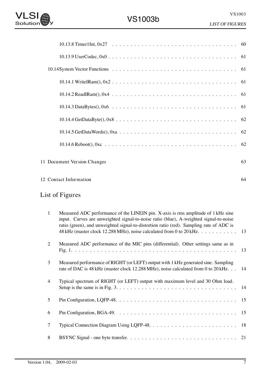
Measured ADC performance of the LINEIN pin. X-axis is rms amplitude of 1 kHz sine
input. Curves are unweighted signal-to-noise ratio (blue), A-weighted signal-to-noise
ratio (green), and unweighted signal-to-distortion ratio (red). Sampling rate of ADC is
48 kHz (master clock 12.288 MHz), noise calculated from 0 to 20 kHz. . . .
. .
. . .
. .
Measured ADC performance of the MIC pins (differential). Other settings same as in
Fig. 1.
. .
. . . . . . . . .
. . . .
. . . .
. . . .
. . .
. . .
. . .
. . .
. . .
. .
.
.
. .
Measured performance of RIGHT (or LEFT) output with 1 kHz generated sine. Sampling
rate of DAC is 48 kHz (master clock 12.288 MHz), noise calculated from 0 to 20 kHz. . .
Typical spectrum of RIGHT (or LEFT) output with maximum level and 30 Ohm load.
Setup is the same is in Fig. 3. . .
. .
. . . . .
. . . .
. . . .
. . .
. . .
. . .
. .
. .
.
.
Pin Configuration, LQFP-48.
.
. .
. . .
. . .
. .
. . . .
. .
. . .
. . .
. . .
. .
. . .
Pin Configuration, BGA-49.
. .
. . .
. .
. . .
. . . . .
. .
. . .
. . .
. . .
. .
. . .
Typical Connection Diagram Using LQFP-48. .
. . . . .
. .
. . .
. . .
. . .
. .
. . .
BSYNC Signal - one byte transfer.
. . .
. . .
. .
. . . .
. .
. . .
. . .
. . .
. .
. . .
.
.
.
.
Version 1.04,
2009-02-03
63
64
13
13
14
14
15
15
18
21
7
VLSISolutiony�
VS1003b
VS1003
LISTOFFIGURES
9
10
11
12
13
14
15
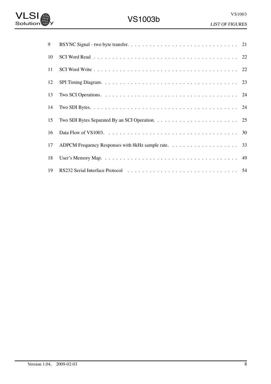
BSYNC Signal - two byte transfer.
. . .
. . .
. .
. . . .
. .
. . .
. . .
. . .
. .
. . .
SCI Word Read . . . .
. .
. . .
. . .
. .
. . .
. . . . .
. .
. . .
. . .
. . .
. .
. . .
SCI Word Write . . . .
. .
. . .
. . .
. .
. . .
. . . . .
. .
. . .
. . .
. . .
. .
. . .
SPI Timing Diagram.
. .
. . .
. .
. . .
. . .
. .
. . . .
. .
. . .
. . .
. . .
. .
. . .
Two SCI Operations.
. .
. . .
. .
. . .
. . .
. .
. . . .
. .
. . .
. . .
. . .
. .
. . .
Two SDI Bytes.
. . . . . .
. . .
. . .
. .
. . .
. . . . .
. .
. . .
. . .
. . .
. .
. . .
Two SDI Bytes Separated By an SCI Operation. . . . . .
. .
. . .
. . .
. . .
. .
. . .
16 Data Flow of VS1003.
.
. . .
. .
. . .
. . .
. .
. . . .
. .
. . .
. . .
. . .
. .
. . .
17 ADPCM Frequency Responses with 8kHz sample rate.
.
. .
. . .
. . .
. . .
. .
. . .
18 User’s Memory Map.
.
. .
. . .
. . .
. .
. . .
. . . . .
. .
. . .
. . .
. . .
. .
. . .
19 RS232 Serial Interface Protocol
.
. . .
. . .
. .
. . . .
. .
. . .
. . .
. . .
. .
. . .
.
.
.
.
.
.
.
.
.
.
.
21
22
22
23
24
24
25
30
33
49
54
Version 1.04,
2009-02-03
8
VLSISolutiony�


 V2版本原理图(Capacitive-Fingerprint-Reader-Schematic_V2).pdf
 摄像头工作原理.doc
 VL53L0X简要说明(En.FLVL53L00216).pdf
 原理图(DVK720-Schematic).pdf
 原理图(Pico-Clock-Green-Schdoc).pdf
 原理图(RS485-CAN-HAT-B-schematic).pdf
 File:SIM7500_SIM7600_SIM7800 Series_SSL_Application Note_V2.00.pdf
 ADS1263(Ads1262).pdf
 原理图(Open429Z-D-Schematic).pdf
 用户手册(Capacitive_Fingerprint_Reader_User_Manual_CN).pdf
 CY7C68013A(英文版)(CY7C68013A).pdf
 TechnicalReference_Dem.pdf