SH1106
132 X 64 Dot Matrix OLED/PLED
Segment/Common Driver with Controller
Features
n Support maximum 132 X 64 dot matrix panel
n Embedded 132 X 64 bits SRAM
n Operating voltage:
- Logic voltage supply: VDD1 = 1.65V - 3.5V
- DC-DC voltage supply: VDD2 = 3.0V - 4.2V
- OLED Operating voltage supply:
External VPP supply = 6.4V - 14.0V
Internal VPP generator = 6.4V - 9.0V
n Maximum segment output current: 200mA
n Maximum common sink current: 27mA
n 8-bit 6800-series parallel interface, 8-bit 8080-series
parallel interface, 3-wire & 4-wire serial peripheral
interface, 400KHz fast I2C bus interface
n Programmable frame frequency and multiplexing ratio
General Description
n Row re-mapping and column re-mapping (ADC)
n Vertical scrolling
n On-chip oscillator
n Programmable Internal charge pump circuit output
n 256-step contrast control on monochrome passive OLED
panel
n Low power consumption
-
-
-
Sleep mode: <5mA
VDD1=0V,VDD2=3.0V – 4.2V: <5mA
VDD1,2=0V,VPP=6.4V –14.0V: <5mA
n Wide range of operating temperatures: -40 to +85°C
n Available in COG form, thickness: 300mm
SH1106 is a single-chip CMOS OLED/PLED driver with controller for organic/polymer light emitting diode dot-matrix graphic
display system. SH1106 consists of 132 segments, 64 commons that can support a maximum display resolution of 132 X 64. It
is designed for Common Cathode type OLED panel.
SH1106 embeds with contrast control, display RAM oscillator and efficient DC-DC converter, which reduces the number of
external components and power consumption. SH1106 is suitable for a wide range of compact portable applications, such as
sub-display of mobile phone, calculator and MP3 player, etc.
1
V2.3
�
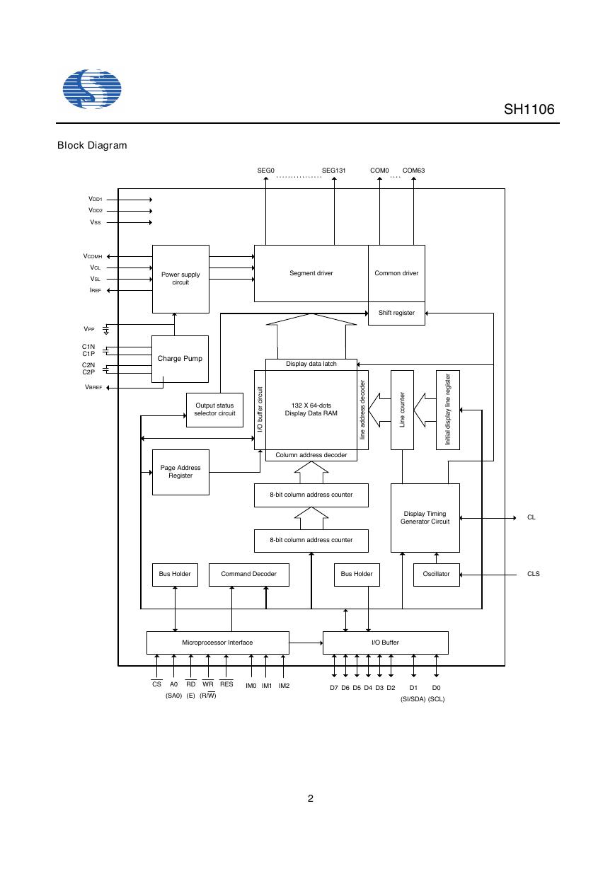
Block Diagram
VDD1
VDD2
VSS
VCOMH
VCL
VSL
IREF
VPP
C1N
C1P
C2N
C2P
VBREF
SH1106
SEG0
SEG131
COM0
COM63
Power supply
circuit
Segment driver
Common driver
Shift register
Charge Pump
Display data latch
Output status
selector circuit
Page Address
Register
r
e
d
o
c
e
d
s
s
e
r
d
d
a
e
n
i
l
t
i
u
c
r
i
c
r
e
f
f
u
b
O
132 X 64-dots
Display Data RAM
/
I
Column address decoder
8-bit column address counter
8-bit column address counter
i
r
e
t
s
g
e
r
e
n
l
i
l
y
a
p
s
d
i
t
r
e
n
u
o
c
e
n
L
i
l
a
i
t
i
n
I
Display Timing
Generator Circuit
CL
Bus Holder
Command Decoder
Bus Holder
Oscillator
CLS
Microprocessor Interface
I/O Buffer
CS
A0
RD
WR
RES
IM0
IM1
IM2
(SA0)
(E)
(R/W)
D7 D6 D5 D4 D3 D2
D1
D0
(SI/SDA) (SCL)
2
�
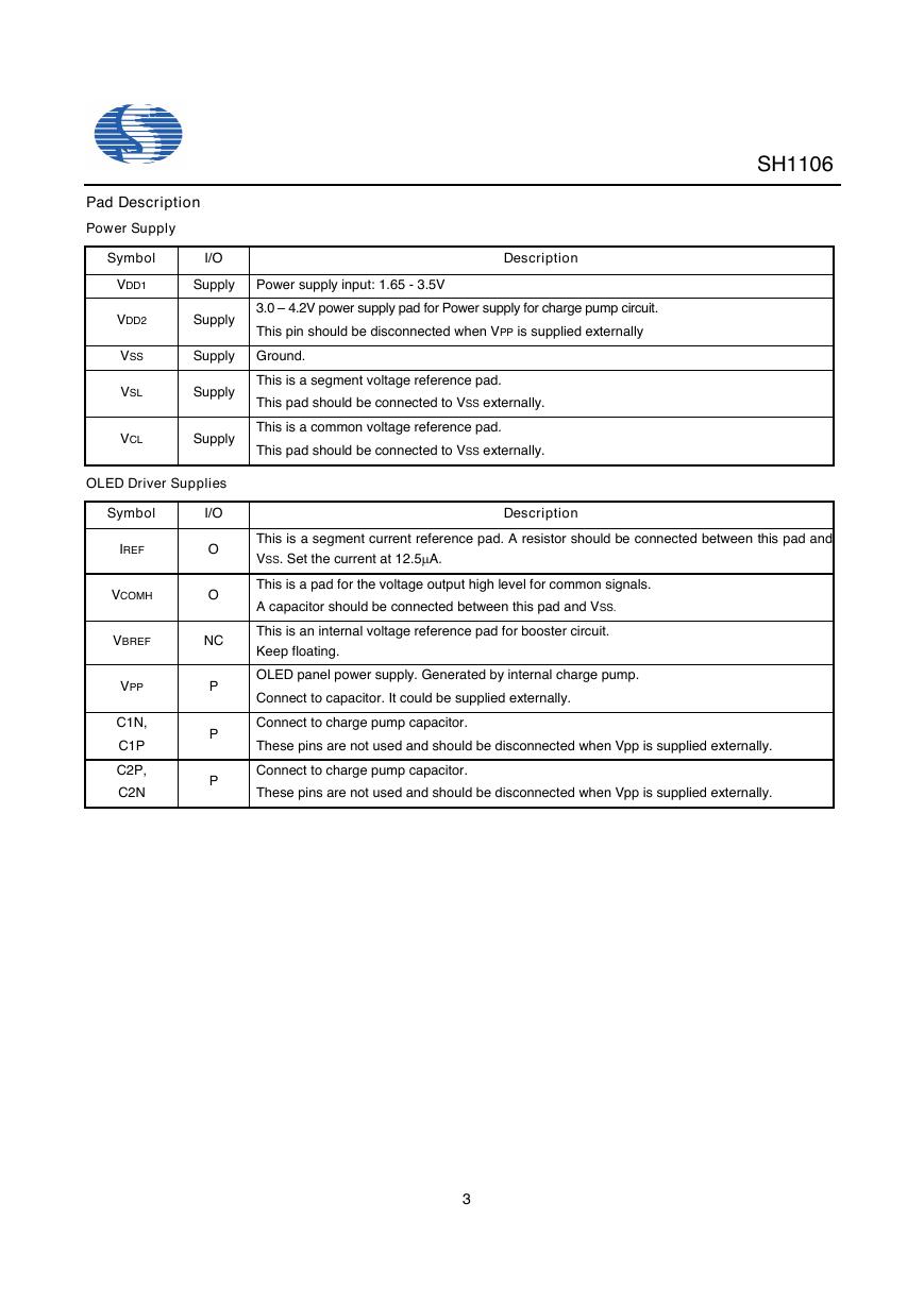
Pad Description
Power Supply
Symbol
I/O
SH1106
Description
VDD1
Supply Power supply input: 1.65 - 3.5V
VDD2
Supply
3.0 – 4.2V power supply pad for Power supply for charge pump circuit.
This pin should be disconnected when VPP is supplied externally
VSS
VSL
Supply Ground.
Supply
This is a segment voltage reference pad.
This pad should be connected to VSS externally.
VCL
Supply
This is a common voltage reference pad.
This pad should be connected to VSS externally.
OLED Driver Supplies
Symbol
I/O
IREF
VCOMH
O
O
Description
This is a segment current reference pad. A resistor should be connected between this pad and
VSS. Set the current at 12.5mA.
This is a pad for the voltage output high level for common signals.
A capacitor should be connected between this pad and VSS.
VBREF
NC
This is an internal voltage reference pad for booster circuit.
Keep floating.
VPP
C1N,
C1P
C2P,
C2N
P
P
P
OLED panel power supply. Generated by internal charge pump.
Connect to capacitor. It could be supplied externally.
Connect to charge pump capacitor.
These pins are not used and should be disconnected when Vpp is supplied externally.
Connect to charge pump capacitor.
These pins are not used and should be disconnected when Vpp is supplied externally.
3
�
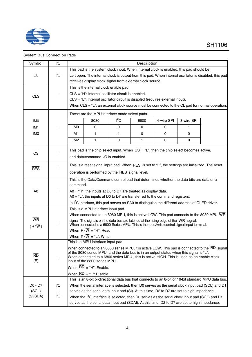
System Bus Connection Pads
SH1106
Symbol
CL
I/O
I/O
CLS
IM0
IM1
IM2
CS
RES
A0
WR
( WR /
)
RD
(E)
I
I
I
I
I
I
I
D0 - D7
(SCL)
(SI/SDA)
I/O
I
I/O
Description
This pad is the system clock input. When internal clock is enabled, this pad should be
Left open. The internal clock is output from this pad. When internal oscillator is disabled, this pad
receives display clock signal from external clock source.
This is the internal clock enable pad.
CLS = “H”: Internal oscillator circuit is enabled.
CLS = “L”: Internal oscillator circuit is disabled (requires external input).
When CLS = “L”, an external clock source must be connected to the CL pad for normal operation.
These are the MPU interface mode select pads.
IM0
IM1
IM2
8080
0
1
1
I2C
0
1
0
6800
4-wire SPI
3-wire SPI
0
0
1
0
0
0
1
0
0
This pad is the chip select input. When CS = “L”, then the chip select becomes active,
and data/command I/O is enabled.
This is a reset signal input pad. When RES is set to “L”, the settings are initialized. The reset
operation is performed by the RES signal level.
= “H”: Read.
= “L”: Write.
This is the Data/Command control pad that determines whether the data bits are data or a
command.
A0 = “H”: the inputs at D0 to D7 are treated as display data.
A0 = “L”: the inputs at D0 to D7 are transferred to the command registers.
In I2C interface, this pad serves as SA0 to distinguish the different address of OLED driver.
This is a MPU interface input pad.
When connected to an 8080 MPU, this is active LOW. This pad connects to the 8080 MPU WR
signal. The signals on the data bus are latched at the rising edge of the WR signal.
When connected to a 6800 Series MPU: This is the read/write control signal input terminal.
When WR /
When WR /
This is a MPU interface input pad.
When connected to an 8080 series MPU, it is active LOW. This pad is connected to the RD signal
of the 8080 series MPU, and the data bus is in an output status when this signal is “L”.
When connected to a 6800 series MPU , this is active HIGH. This is used as an enable clock
input of the 6800 series MPU.
When RD = “H”: Enable.
When RD = “L”: Disable.
This is an 8-bit bi-directional data bus that connects to an 8-bit or 16-bit standard MPU data bus.
When the serial interface is selected, then D0 serves as the serial clock input pad (SCL) and D1
serves as the serial data input pad (SI). At this time, D2 to D7 are set to high impedance.
When the I2C interface is selected, then D0 serves as the serial clock input pad (SCL) and D1
serves as the serial data input pad (SDAI). At this time, D2 to D7 are set to high impedance.
4
�
SH1106
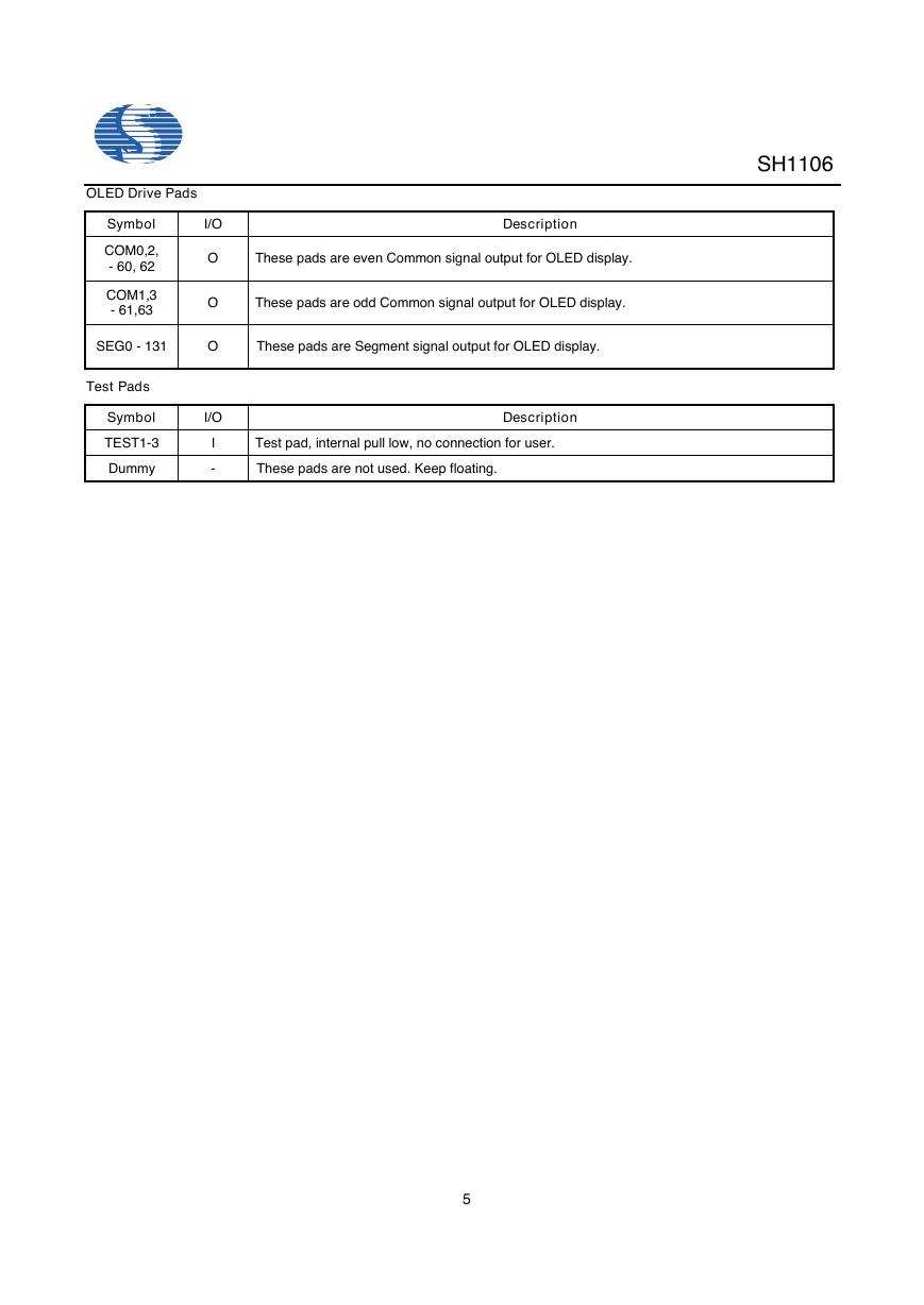
OLED Drive Pads
Symbol
I/O
COM0,2,
- 60, 62
COM1,3
- 61,63
SEG0 - 131
Test Pads
Symbol
TEST1-3
Dummy
O
O
O
I/O
I
-
Description
These pads are even Common signal output for OLED display.
These pads are odd Common signal output for OLED display.
These pads are Segment signal output for OLED display.
Test pad, internal pull low, no connection for user.
These pads are not used. Keep floating.
Description
5
�
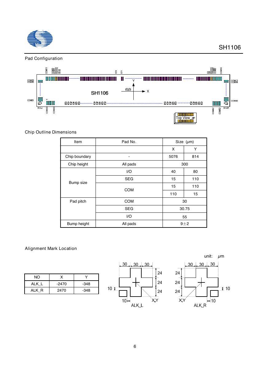
Pad Configuration
Chip Outline Dimensions
Item
Chip boundary
Chip height
Bump size
Pad pitch
Bump height
Pad No.
Size (µm)
-
All pads
I/O
SEG
COM
COM
SEG
I/O
All pads
X
5076
40
15
15
110
Y
814
80
110
110
15
300
30
30.75
55
9±2
Alignment Mark Location
NO
ALK_L
ALK_R
X
-2470
2470
Y
-348
-348
6
SH1106
unit: µm
�
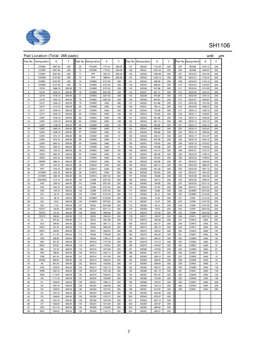
Pad Location (Total: 266 pads)
Pad No. Designation
Pad No. Designation
X
Y
X
Y
Pad No. Designation
X
Pad No. Designation
-2287.62
-2257.62
-2227.62
-2197.62
-2167.62
-2137.62
-1688.19
-329
-329
-329
-329
-329
-329
-299.95
-1633.19
-299.95
-1578.19
-299.95
-1523.19
-299.95
-1468.19
-299.95
-1413.19
-299.95
-1358.19
-299.95
-1303.19
-299.95
-1248.19
-299.95
-1193.19
-299.95
-1138.19
-299.95
-1083.19
-1028.19
-973.19
-918.19
-863.19
-808.19
-753.19
-698.19
-643.19
-588.19
-533.19
-478.19
-423.19
-368.19
-313.19
-258.19
-203.19
-148.19
-93.19
-38.19
16.81
71.81
126.81
181.81
236.81
291.81
346.81
401.81
456.81
511.81
566.81
621.81
676.81
731.81
786.81
841.81
896.81
951.81
1006.81
1061.81
1116.81
1171.81
1226.81
1281.81
1336.81
1391.81
1446.81
1501.81
1556.81
1611.81
1666.81
-299.95
-299.95
-299.95
-299.95
-299.95
-299.95
-299.95
-299.95
-299.95
-299.95
-299.95
-299.95
-299.95
-299.95
-299.95
-299.95
-299.95
-299.95
-299.95
-299.95
-299.95
-299.95
-299.95
-299.95
-299.95
-299.95
-299.95
-299.95
-299.95
-299.95
-299.95
-299.95
-299.95
-299.95
-299.95
-299.95
-299.95
-299.95
-299.95
-299.95
-299.95
-299.95
-299.95
-299.95
-299.95
-299.95
-299.95
-299.95
-299.95
-299.95
-299.95
69
70
71
72
73
74
75
76
77
78
79
80
81
82
83
84
85
86
87
88
89
90
91
92
93
94
95
96
97
98
99
100
101
102
103
104
105
106
107
108
109
110
111
112
113
114
115
116
117
118
119
120
121
122
123
124
125
126
127
128
129
130
131
132
133
134
135
136
VCOMH
VCOMH
VPP
VPP
COM62
COM60
COM58
COM56
COM54
COM52
COM50
COM48
COM46
COM44
COM42
COM40
COM38
COM36
COM34
COM32
COM30
COM28
COM26
COM24
COM22
COM20
COM18
COM16
COM14
COM12
COM10
COM8
COM6
COM4
COM2
COM0
DUMMY
DUMMY
SEG0
SEG1
SEG2
SEG3
SEG4
SEG5
SEG6
SEG7
SEG8
SEG9
SEG10
SEG11
SEG12
SEG13
SEG14
SEG15
SEG16
SEG17
SEG18
SEG19
SEG20
SEG21
SEG22
SEG23
SEG24
SEG25
SEG26
SEG27
SEG28
SEG29
1721.81
1776.81
1831.81
1886.81
2137.62
2167.62
2197.62
2227.62
2257.62
2287.62
2460
2460
2460
2460
2460
2460
2460
2460
2460
2460
2460
2460
2460
2460
2460
2460
2460
2460
2460
2460
2287.62
2257.62
2227.62
2197.62
2167.62
2137.62
2105.63
2075.63
2044.88
2014.13
1983.38
1952.63
1921.88
1891.13
1860.38
1829.63
1798.88
1768.13
1737.38
1706.63
1675.88
1645.13
1614.38
1583.63
1552.88
1522.13
1491.38
1460.63
1429.88
1399.13
1368.38
1337.63
1306.88
1276.13
1245.38
1214.63
1183.88
1153.13
-299.95
-299.95
-299.95
-299.95
-329
-329
-329
-329
-329
-329
-285
-255
-225
-195
-165
-135
-105
-75
-45
-15
15
45
75
105
135
165
195
225
255
285
329
329
329
329
329
329
329
329
329
329
329
329
329
329
329
329
329
329
329
329
329
329
329
329
329
329
329
329
329
329
329
329
329
329
329
329
329
329
1
2
3
4
5
6
7
8
9
10
11
12
13
14
15
16
17
18
19
20
21
22
23
24
25
26
27
28
29
30
31
32
33
34
35
36
37
38
39
40
41
42
43
44
45
46
47
48
49
50
51
52
53
54
55
56
57
58
59
60
61
62
63
64
65
66
67
68
COM53
COM55
COM57
COM59
COM61
COM63
C21N
C21N
C21N
C21N
C21P
C21P
C21P
C21P
C22P
C22P
C22P
C22P
C22N
C22N
C22N
C22N
VDD2
VDD2
VDD2
VDD2
VBREF
VPP
VPP
VCOMH
VCOMH
VSS(REF)
VSS
VSS
VSS
VCL
VCL
VSL
VSL
TEST1
TEST2
TEST3
CL
CLS
VDD1
VDD1
IM1
VSS
IM2
VDD1
IM0
VSS
CSB
RESB
A0
VSS
WRB
RDB
D0
D1
D2
D3
D4
D5
D6
D7
VSS
IREF
SEG30
SEG31
SEG32
SEG33
SEG34
SEG35
SEG36
SEG37
SEG38
SEG39
SEG40
SEG41
SEG42
SEG43
SEG44
SEG45
SEG46
SEG47
SEG48
SEG49
SEG50
SEG51
SEG52
SEG53
SEG54
SEG55
SEG56
SEG57
SEG58
SEG59
SEG60
SEG61
SEG62
SEG63
SEG64
SEG65
SEG66
SEG67
SEG68
SEG69
SEG70
SEG71
SEG72
SEG73
SEG74
SEG75
SEG76
SEG77
SEG78
SEG79
SEG80
SEG81
SEG82
SEG83
SEG84
SEG85
SEG86
SEG87
SEG88
SEG89
SEG90
SEG91
SEG92
SEG93
SEG94
SEG95
SEG96
SEG97
1122.38
1091.63
1060.88
1030.13
999.38
968.63
937.88
907.13
876.38
845.63
814.88
784.13
753.38
722.63
691.88
661.13
630.38
599.63
568.88
538.13
507.38
476.63
445.88
415.13
384.38
353.63
322.88
292.13
261.38
230.63
199.88
169.13
138.38
107.63
76.88
46.13
15.38
-15.37
-46.12
-76.87
-107.62
-138.37
-230.62
-261.37
-292.12
-322.87
-353.62
-384.37
-415.12
-445.87
-476.62
-507.37
-538.12
-568.87
-599.62
-630.37
-661.12
-691.87
-722.62
-753.37
-784.12
-814.87
-845.62
-876.37
-907.12
-937.87
-968.62
-999.37
137
138
139
140
141
142
143
144
145
146
147
148
149
150
151
152
153
154
155
156
157
158
159
160
161
162
163
164
165
166
167
168
169
170
171
172
173
174
175
176
177
178
179
180
181
182
183
184
185
186
187
188
189
190
191
192
193
194
195
196
197
198
199
200
201
202
203
204
7
Y
329
329
329
329
329
329
329
329
329
329
329
329
329
329
329
329
329
329
329
329
329
329
329
329
329
329
329
329
329
329
329
329
329
329
329
329
329
329
329
329
329
329
329
329
329
329
329
329
329
329
329
329
329
329
329
329
329
329
329
329
329
329
329
329
329
329
329
329
SH1106
uunniitt:: µµmm
X
Y
205
206
207
208
209
210
211
212
213
214
215
216
217
218
219
220
221
222
223
224
225
226
227
228
229
230
231
232
233
234
235
236
237
238
239
240
241
242
243
244
245
246
247
248
249
250
251
252
253
254
255
256
257
258
259
260
261
262
263
264
265
266
SEG98
SEG99
-1030.12
-1060.87
SEG100
-1091.62
SEG101
-1122.37
SEG102
-1153.12
SEG103
SEG104
-1183.87
-1214.62
SEG105
-1245.37
SEG106
-1276.12
SEG107
-1306.87
SEG108
-1337.62
SEG109
-1368.37
SEG110
-1399.12
SEG111
-1429.87
SEG112
-1460.62
SEG113
-1491.37
SEG114
-1522.12
SEG115
SEG116
-1552.87
-1583.62
SEG117
-1614.37
SEG118
-1645.12
SEG119
-1675.87
SEG120
-1706.62
SEG121
-1737.37
SEG122
-1768.12
SEG123
-1798.87
SEG124
-1829.62
SEG125
-1860.37
SEG126
-1891.12
SEG127
SEG128
-1921.87
-1952.62
SEG129
-1983.37
SEG130
-2014.12
SEG131
-2044.87
DUMMY
-2075.62
DUMMY
-2105.62
COM1
COM3
COM5
COM7
COM9
COM11
COM13
COM15
COM17
COM19
COM21
COM23
COM25
COM27
COM29
COM31
COM33
COM35
COM37
COM39
COM41
COM43
COM45
COM47
COM49
COM51
-2137.62
-2167.62
-2197.62
-2227.62
-2257.62
-2287.62
-2460
-2460
-2460
-2460
-2460
-2460
-2460
-2460
-2460
-2460
-2460
-2460
-2460
-2460
-2460
-2460
-2460
-2460
-2460
-2460
329
329
329
329
329
329
329
329
329
329
329
329
329
329
329
329
329
329
329
329
329
329
329
329
329
329
329
329
329
329
329
329
329
329
329
329
329
329
329
329
329
329
285
255
225
195
165
135
105
75
45
15
-15
-45
-75
-105
-135
-165
-195
-225
-255
-285
�
Functional Description
SH1106
Microprocessor Interface Selection
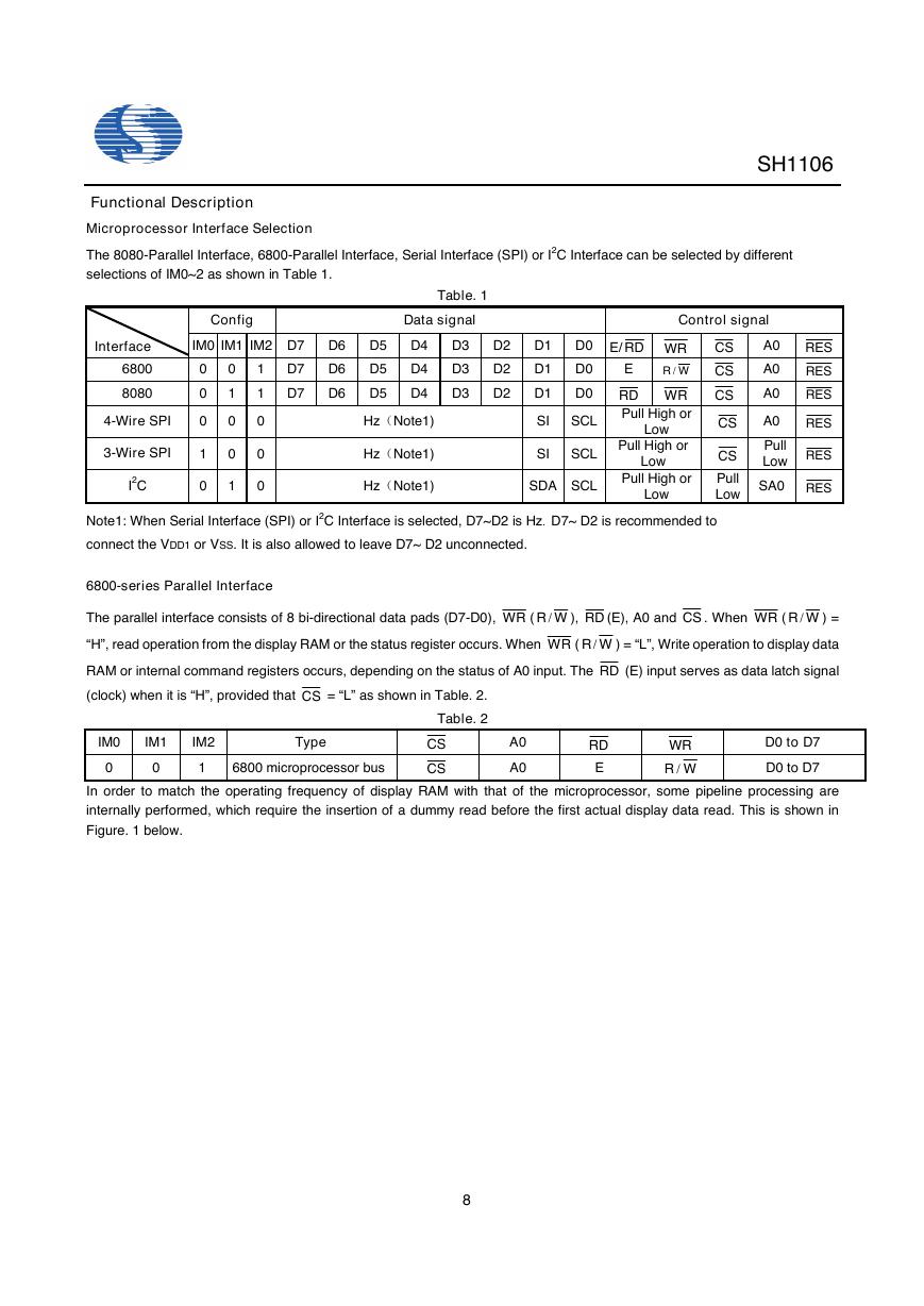
The 8080-Parallel Interface, 6800-Parallel Interface, Serial Interface (SPI) or I2C Interface can be selected by different
selections of IM0~2 as shown in Table 1.
Table. 1
Data signal
D6
D6
D6
D5
D5
D5
D4
D4
D4
D3
D3
D3
D2
D2
D2
D1
D1
D1
Interface
6800
8080
4-Wire SPI
3-Wire SPI
I2C
Config
IM0 IM1 IM2 D7
0
0
0
1
0
0
1
0
0
1
1 D7
1 D7
0
0
0
Control signal
E
D0 E/ RD WR CS
CS
D0
RD WR CS
Pull High or
WR /
D0
A0
A0
A0
A0
RES
RES
RES
RES
Hz(Note1)
Hz(Note1)
Hz(Note1)
SI SCL
Low
CS
SI SCL
SDA SCL
Pull High or
Low
Pull High or
Low
CS
Pull
Low
Pull
Low RES
SA0 RES
Note1: When Serial Interface (SPI) or I2C Interface is selected, D7~D2 is Hz. D7~ D2 is recommended to
connect the VDD1 or VSS. It is also allowed to leave D7~ D2 unconnected.
6800-series Parallel Interface
The parallel interface consists of 8 bi-directional data pads (D7-D0), WR ( WR /
), RD (E), A0 and CS . When WR ( WR /
) =
“H”, read operation from the display RAM or the status register occurs. When WR ( WR /
) = “L”, Write operation to display data
RAM or internal command registers occurs, depending on the status of A0 input. The RD (E) input serves as data latch signal
(clock) when it is “H”, provided that CS = “L” as shown in Table. 2.
Table. 2
IM0
IM1
IM2
Type
0
0
1
6800 microprocessor bus
CS
CS
A0
A0
RD
E
WR
WR /
D0 to D7
D0 to D7
In order to match the operating frequency of display RAM with that of the microprocessor, some pipeline processing are
internally performed, which require the insertion of a dummy read before the first actual display data read. This is shown in
Figure. 1 below.
8
�


 V2版本原理图(Capacitive-Fingerprint-Reader-Schematic_V2).pdf
 摄像头工作原理.doc
 VL53L0X简要说明(En.FLVL53L00216).pdf
 原理图(DVK720-Schematic).pdf
 原理图(Pico-Clock-Green-Schdoc).pdf
 原理图(RS485-CAN-HAT-B-schematic).pdf
 File:SIM7500_SIM7600_SIM7800 Series_SSL_Application Note_V2.00.pdf
 ADS1263(Ads1262).pdf
 原理图(Open429Z-D-Schematic).pdf
 用户手册(Capacitive_Fingerprint_Reader_User_Manual_CN).pdf
 CY7C68013A(英文版)(CY7C68013A).pdf
 TechnicalReference_Dem.pdf