logo资料库

datasheet(DS_SX1261-2_V1.2).pdf

第1页 / 共111页
第2页 / 共111页
第3页 / 共111页
第4页 / 共111页
第5页 / 共111页
第6页 / 共111页
第7页 / 共111页
第8页 / 共111页
资料共111页,剩余部分请下载后查看
Table of Contents
List of Figures
List of Tables
1. Architecture
2. Pin Connection
2.1 I/O Description
2.2 Package View
3. Specifications
3.1 ESD Notice
3.2 Absolute Maximum Ratings
3.3 Operating Range
3.4 Crystal Specifications
3.5 Electrical Specifications
3.5.1 Power Consumption
3.5.2 General Specifications
3.5.3 Receive Mode Specifications
3.5.4 Transmit Mode Specifications
3.5.5 Digital I/O Specifications
4. Circuit Description
4.1 Clock References
4.1.1 RC Frequency References
4.1.2 High-Precision Frequency Reference
4.1.3 XTAL Control Block
4.1.4 TCXO Control Block
4.2 Phase-Locked Loop (PLL)
4.3 Receiver
4.3.1 Intermediate Frequencies
4.4 Transmitter
4.4.1 SX1261 Power Amplifier Specifics
4.4.2 SX1262 Power Amplifier Specifics
4.4.3 Power Amplifier Summary
5. Power Distribution
5.1 Selecting DC-DC Converter or LDO Regulation
5.1.1 Option A: SX1261 with DC-DC Regulator
5.1.2 Option B: SX1261 with LDO Regulator
5.1.3 Option C: SX1262 with DC-DC Regulator
5.1.4 Option D: SX1262 with LDO Regulator
5.1.5 Consideration on the DC-DC Inductor Selection
5.2 Flexible DIO Supply
6. Modems
6.1 LoRa® Modem
6.1.1 Modulation Parameter
6.1.2 LoRa® Packet Engine
6.1.3 LoRa® Frame
6.1.4 LoRa® Time-on-Air
6.1.5 LoRa® Channel Activity Detection (CAD)
6.2 FSK Modem
6.2.1 Modulation Parameter
6.2.2 FSK Packet Engine
6.2.3 FSK Packet Format
7. Data Buffer
7.1 Principle of Operation
7.2 Data Buffer in Receive Mode
7.3 Data Buffer in Transmit Mode
7.4 Using the Data Buffer
8. Digital Interface and Control
8.1 Reset
8.2 SPI Interface
8.2.1 SPI Timing When the Transceiver is in Active Mode
8.2.2 SPI Timing When the Transceiver Leaves Sleep Mode
8.3 Multi-Purpose Digital Input/Output (DIO)
8.3.1 BUSY Control Line
8.3.2 Digital Input/Output
8.4 Digital Interface Status versus Chip modes
8.5 IRQ Handling
9. Operational Modes
9.1 Startup
9.2 Calibration
9.2.1 Image Calibration for Specific Frequency Bands
9.3 Sleep Mode
9.4 Standby (STDBY) Mode
9.5 Frequency Synthesis (FS) Mode
9.6 Receive (RX) Mode
9.6.1 PA Ramping
9.7 Active Mode Switching Time
9.8 Transceiver Circuit Modes Graphical Illustration
10. Host Controller Interface
10.1 Command Structure
10.2 Transaction Termination
11. List of Commands
11.1 Operational Modes Commands
11.2 Register and Buffer Access Commands
11.3 DIO and IRQ Control
11.4 RF, Modulation and Packet Commands
11.5 Status Commands
12. Register Map
12.1 Register Table
13. Commands Interface
13.1 Operational Modes Functions
13.1.1 SetSleep
13.1.2 SetStandby
13.1.3 SetFs
13.1.4 SetTx
13.1.5 SetRx
13.1.6 StopTimerOnPreamble
13.1.7 SetRxDutyCycle
13.1.8 SetCAD
13.1.9 SetTxContinuousWave
13.1.10 SetTxInfinitePreamble
13.1.11 SetRegulatorMode
13.1.12 Calibrate Function
13.1.13 CalibrateImage
13.1.14 SetPaConfig
13.1.15 SetRxTxFallbackMode
13.2 Registers and Buffer Access
13.2.1 WriteRegister Function
13.2.2 ReadRegister Function
13.2.3 WriteBuffer Function
13.2.4 ReadBuffer Function
13.3 DIO and IRQ Control Functions
13.3.1 SetDioIrqParams
13.3.2 IrqMask
13.3.3 GetIrqStatus
13.3.4 ClearIrqStatus
13.3.5 SetDIO2AsRfSwitchCtrl
13.3.6 SetDIO3AsTCXOCtrl
13.4 RF Modulation and Packet-Related Functions
13.4.1 SetRfFrequency
13.4.2 SetPacketType
13.4.3 GetPacketType
13.4.4 SetTxParams
13.4.5 SetModulationParams
13.4.6 SetPacketParams
13.4.7 SetCadParams
13.4.8 SetBufferBaseAddress
13.4.9 SetLoRaSymbNumTimeout
13.5 Communication Status Information
13.5.1 GetStatus
13.5.2 GetRxBufferStatus
13.5.3 GetPacketStatus
13.5.4 GetRssiInst
13.5.5 GetStats
13.5.6 ResetStats
13.6 Miscellaneous
13.6.1 GetDeviceErrors
13.6.2 ClearDeviceErrors
14. Application
14.1 HOST API Basic Read Write Function
14.2 Circuit Configuration for Basic Tx Operation
14.3 Circuit Configuration for Basic Rx Operation
14.4 Issuing Commands in the Right Order
14.5 Application Schematics
14.5.1 Application Design of the SX1261 with RF Switch
14.5.2 Application Design of the SX1262 with RF Switch
15. Known Limitations
15.1 Modulation Quality with 500 kHz LoRa® Bandwidth
15.1.1 Description
15.1.2 Workaround
15.2 Better Resistance of the SX1262 Tx to Antenna Mismatch
15.2.1 Description
15.2.2 Workaround
15.3 Implicit Header Mode Timeout Behavior
15.3.1 Description
15.3.2 Workaround
15.4 Optimizing the Inverted IQ Operation
15.4.1 Description
15.4.2 Workaround
16. Packaging Information
16.1 Package Outline Drawing
16.2 Package Marking
16.3 Land Pattern
16.4 Reflow Profiles
Glossary
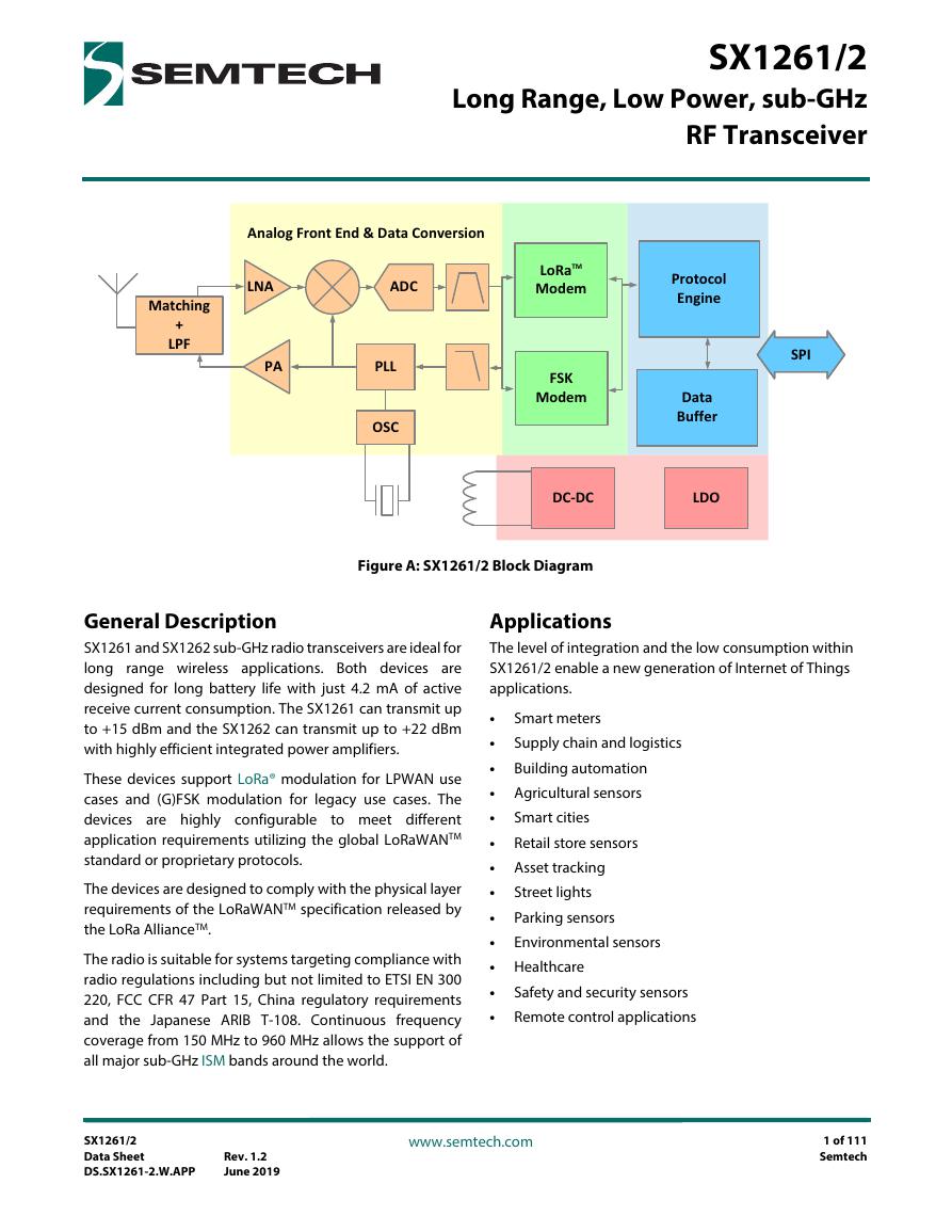
SX1261/2 Long Range, Low Power, sub-GHz RF Transceiver Matching + LPF Analog Front End & Data Conversion LNA ADC PA PLL OSC LoRaTM Modem FSK Modem Protocol Engine Data Buffer SPI DC-DC LDO Figure A: SX1261/2 Block Diagram General Description SX1261 and SX1262 sub-GHz radio transceivers are ideal for long range wireless applications. Both devices are designed for long battery life with just 4.2 mA of active receive current consumption. The SX1261 can transmit up to +15 dBm and the SX1262 can transmit up to +22 dBm with highly efficient integrated power amplifiers. These devices support LoRa® modulation for LPWAN use cases and (G)FSK modulation for legacy use cases. The devices are highly configurable to meet different application requirements utilizing the global LoRaWANTM standard or proprietary protocols. The devices are designed to comply with the physical layer requirements of the LoRaWANTM specification released by the LoRa AllianceTM. The radio is suitable for systems targeting compliance with radio regulations including but not limited to ETSI EN 300 220, FCC CFR 47 Part 15, China regulatory requirements and the Japanese ARIB T-108. Continuous frequency coverage from 150 MHz to 960 MHz allows the support of all major sub-GHz ISM bands around the world. Applications The level of integration and the low consumption within SX1261/2 enable a new generation of Internet of Things applications. Smart meters Supply chain and logistics Building automation Agricultural sensors Smart cities Retail store sensors Asset tracking Street lights Parking sensors Environmental sensors • • • • • • • • • • • Healthcare • • Safety and security sensors Remote control applications SX1261/2 Data Sheet DS.SX1261-2.W.APP Rev. 1.2 June 2019 www.semtech.com 1 of 111 Semtech
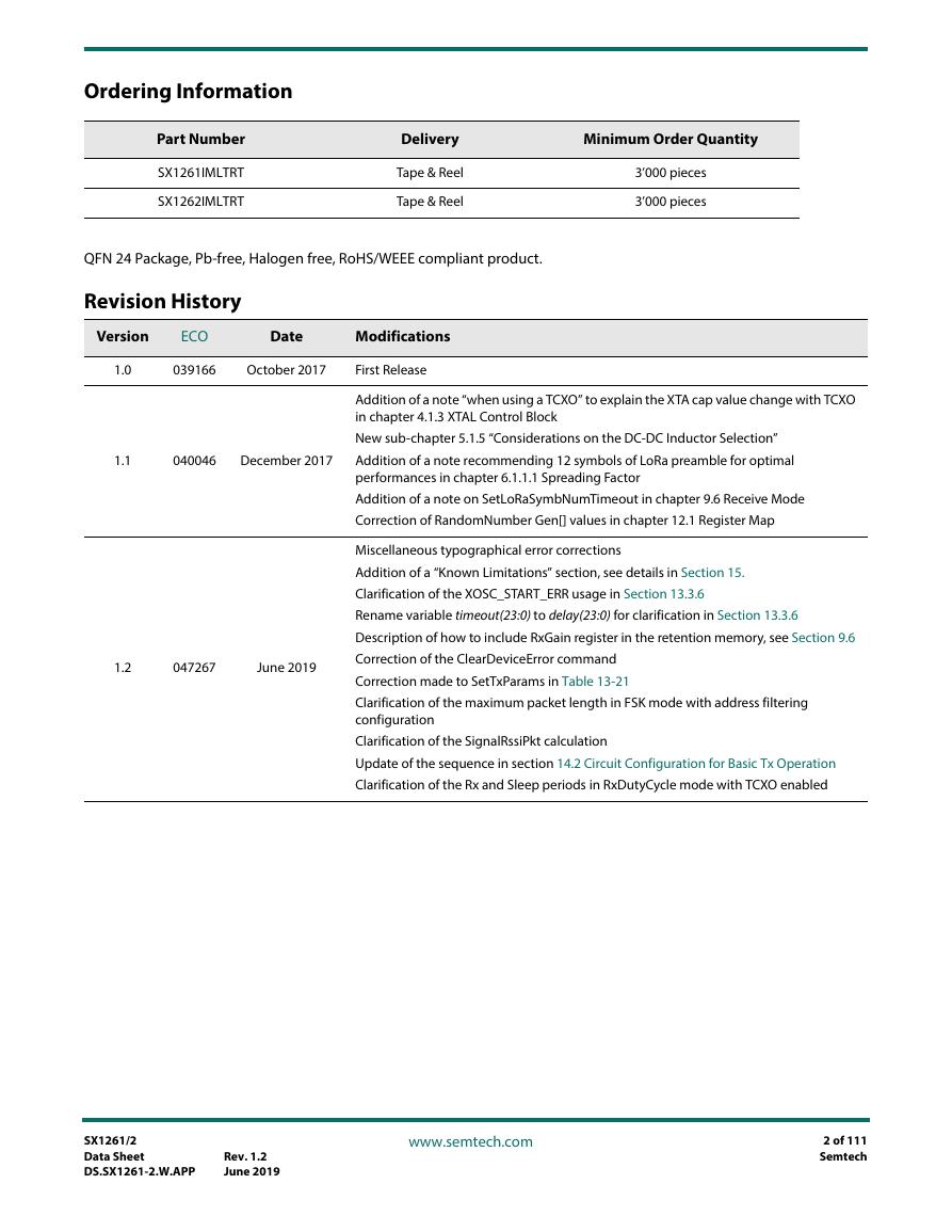
Ordering Information Part Number SX1261IMLTRT SX1262IMLTRT Delivery Tape & Reel Tape & Reel Minimum Order Quantity 3’000 pieces 3’000 pieces QFN 24 Package, Pb-free, Halogen free, RoHS/WEEE compliant product. Revision History Version ECO Date Modifications 1.0 039166 October 2017 First Release 1.1 040046 December 2017 1.2 047267 June 2019 Addition of a note “when using a TCXO” to explain the XTA cap value change with TCXO in chapter 4.1.3 XTAL Control Block New sub-chapter 5.1.5 “Considerations on the DC-DC Inductor Selection” Addition of a note recommending 12 symbols of LoRa preamble for optimal performances in chapter 6.1.1.1 Spreading Factor Addition of a note on SetLoRaSymbNumTimeout in chapter 9.6 Receive Mode Correction of RandomNumber Gen[] values in chapter 12.1 Register Map Miscellaneous typographical error corrections Addition of a “Known Limitations” section, see details in Section 15. Clarification of the XOSC_START_ERR usage in Section 13.3.6 Rename variable timeout(23:0) to delay(23:0) for clarification in Section 13.3.6 Description of how to include RxGain register in the retention memory, see Section 9.6 Correction of the ClearDeviceError command Correction made to SetTxParams in Table 13-21 Clarification of the maximum packet length in FSK mode with address filtering configuration Clarification of the SignalRssiPkt calculation Update of the sequence in section 14.2 Circuit Configuration for Basic Tx Operation Clarification of the Rx and Sleep periods in RxDutyCycle mode with TCXO enabled SX1261/2 Data Sheet DS.SX1261-2.W.APP Rev. 1.2 June 2019 www.semtech.com 2 of 111 Semtech
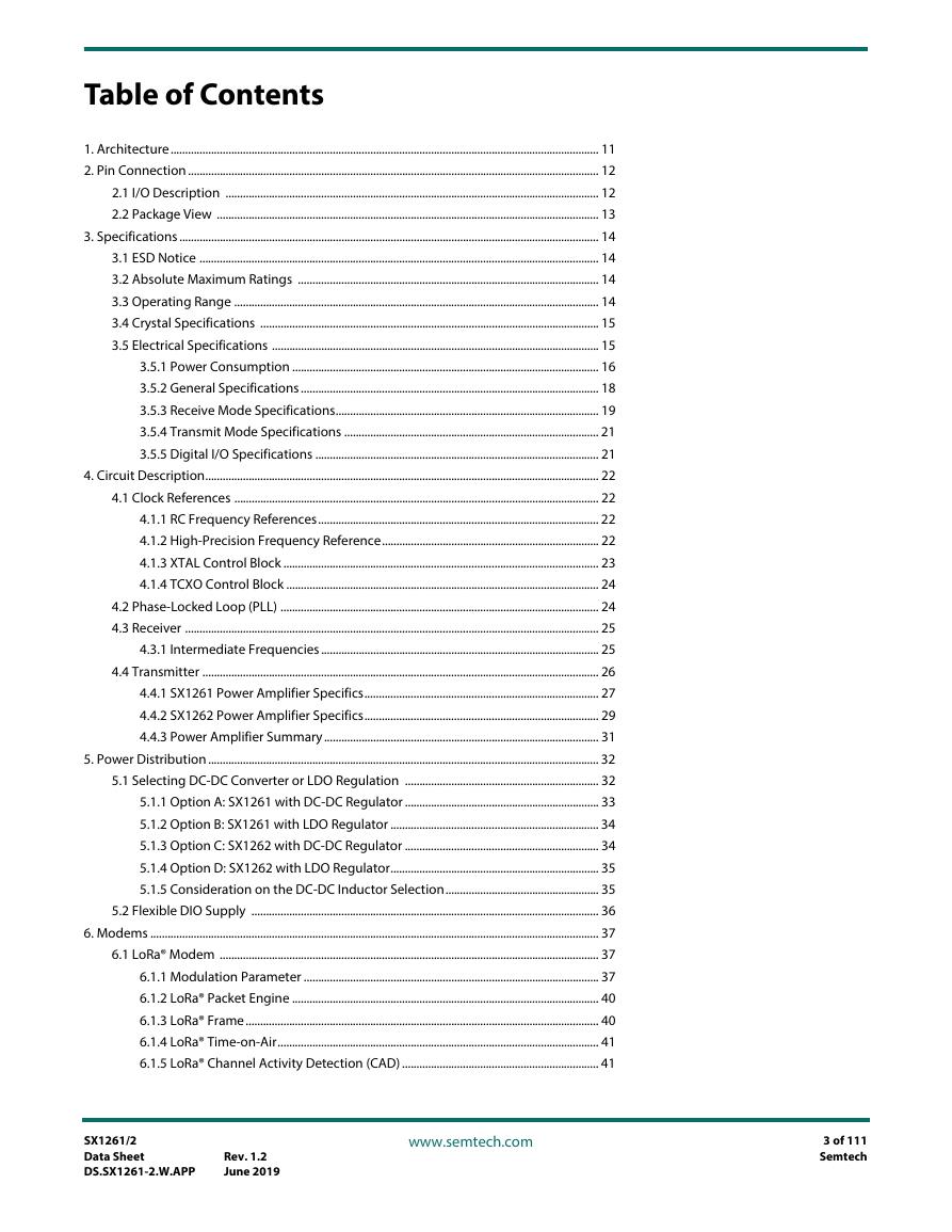
Table of Contents 1. Architecture.................................................................................................................................................... 11 2. Pin Connection .............................................................................................................................................. 12 2.1 I/O Description ................................................................................................................................. 12 2.2 Package View .................................................................................................................................... 13 3. Specifications ................................................................................................................................................. 14 3.1 ESD Notice .......................................................................................................................................... 14 3.2 Absolute Maximum Ratings ........................................................................................................ 14 3.3 Operating Range .............................................................................................................................. 14 3.4 Crystal Specifications ..................................................................................................................... 15 3.5 Electrical Specifications ................................................................................................................. 15 3.5.1 Power Consumption .......................................................................................................... 16 3.5.2 General Specifications ....................................................................................................... 18 3.5.3 Receive Mode Specifications........................................................................................... 19 3.5.4 Transmit Mode Specifications ........................................................................................ 21 3.5.5 Digital I/O Specifications .................................................................................................. 21 4. Circuit Description........................................................................................................................................ 22 4.1 Clock References .............................................................................................................................. 22 4.1.1 RC Frequency References................................................................................................. 22 4.1.2 High-Precision Frequency Reference........................................................................... 22 4.1.3 XTAL Control Block ............................................................................................................. 23 4.1.4 TCXO Control Block ............................................................................................................ 24 4.2 Phase-Locked Loop (PLL) .............................................................................................................. 24 4.3 Receiver ............................................................................................................................................... 25 4.3.1 Intermediate Frequencies ................................................................................................ 25 4.4 Transmitter ......................................................................................................................................... 26 4.4.1 SX1261 Power Amplifier Specifics................................................................................. 27 4.4.2 SX1262 Power Amplifier Specifics................................................................................. 29 4.4.3 Power Amplifier Summary............................................................................................... 31 5. Power Distribution ....................................................................................................................................... 32 5.1 Selecting DC-DC Converter or LDO Regulation ................................................................... 32 5.1.1 Option A: SX1261 with DC-DC Regulator ................................................................... 33 5.1.2 Option B: SX1261 with LDO Regulator ........................................................................ 34 5.1.3 Option C: SX1262 with DC-DC Regulator ................................................................... 34 5.1.4 Option D: SX1262 with LDO Regulator........................................................................ 35 5.1.5 Consideration on the DC-DC Inductor Selection..................................................... 35 5.2 Flexible DIO Supply ........................................................................................................................ 36 6. Modems ........................................................................................................................................................... 37 6.1 LoRa® Modem ................................................................................................................................... 37 6.1.1 Modulation Parameter ...................................................................................................... 37 6.1.2 LoRa® Packet Engine .......................................................................................................... 40 6.1.3 LoRa® Frame.......................................................................................................................... 40 6.1.4 LoRa® Time-on-Air............................................................................................................... 41 6.1.5 LoRa® Channel Activity Detection (CAD) .................................................................... 41 SX1261/2 Data Sheet DS.SX1261-2.W.APP Rev. 1.2 June 2019 www.semtech.com 3 of 111 Semtech
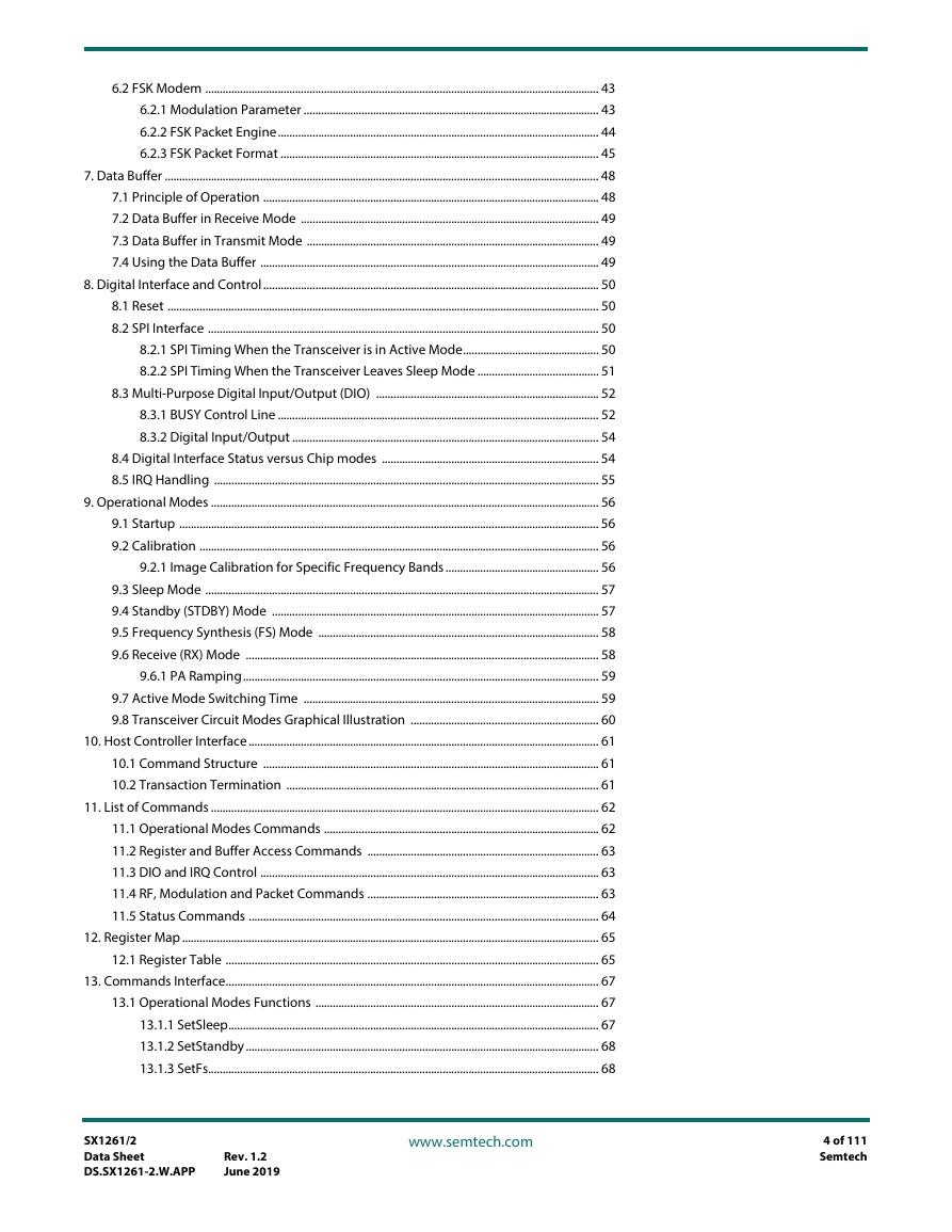
6.2 FSK Modem ........................................................................................................................................ 43 6.2.1 Modulation Parameter ...................................................................................................... 43 6.2.2 FSK Packet Engine............................................................................................................... 44 6.2.3 FSK Packet Format .............................................................................................................. 45 7. Data Buffer ...................................................................................................................................................... 48 7.1 Principle of Operation .................................................................................................................... 48 7.2 Data Buffer in Receive Mode ....................................................................................................... 49 7.3 Data Buffer in Transmit Mode ..................................................................................................... 49 7.4 Using the Data Buffer ..................................................................................................................... 49 8. Digital Interface and Control.................................................................................................................... 50 8.1 Reset ..................................................................................................................................................... 50 8.2 SPI Interface ....................................................................................................................................... 50 8.2.1 SPI Timing When the Transceiver is in Active Mode............................................... 50 8.2.2 SPI Timing When the Transceiver Leaves Sleep Mode .......................................... 51 8.3 Multi-Purpose Digital Input/Output (DIO) ............................................................................. 52 8.3.1 BUSY Control Line ............................................................................................................... 52 8.3.2 Digital Input/Output .......................................................................................................... 54 8.4 Digital Interface Status versus Chip modes ........................................................................... 54 8.5 IRQ Handling ..................................................................................................................................... 55 9. Operational Modes ...................................................................................................................................... 56 9.1 Startup ................................................................................................................................................. 56 9.2 Calibration .......................................................................................................................................... 56 9.2.1 Image Calibration for Specific Frequency Bands..................................................... 56 9.3 Sleep Mode ........................................................................................................................................ 57 9.4 Standby (STDBY) Mode ................................................................................................................. 57 9.5 Frequency Synthesis (FS) Mode ................................................................................................. 58 9.6 Receive (RX) Mode .......................................................................................................................... 58 9.6.1 PA Ramping........................................................................................................................... 59 9.7 Active Mode Switching Time ...................................................................................................... 59 9.8 Transceiver Circuit Modes Graphical Illustration ................................................................. 60 10. Host Controller Interface ......................................................................................................................... 61 10.1 Command Structure .................................................................................................................... 61 10.2 Transaction Termination ............................................................................................................ 61 11. List of Commands ...................................................................................................................................... 62 11.1 Operational Modes Commands ............................................................................................... 62 11.2 Register and Buffer Access Commands ................................................................................ 63 11.3 DIO and IRQ Control ..................................................................................................................... 63 11.4 RF, Modulation and Packet Commands ................................................................................ 63 11.5 Status Commands ......................................................................................................................... 64 12. Register Map ................................................................................................................................................ 65 12.1 Register Table ................................................................................................................................. 65 13. Commands Interface................................................................................................................................. 67 13.1 Operational Modes Functions .................................................................................................. 67 13.1.1 SetSleep................................................................................................................................ 67 13.1.2 SetStandby.......................................................................................................................... 68 13.1.3 SetFs....................................................................................................................................... 68 SX1261/2 Data Sheet DS.SX1261-2.W.APP Rev. 1.2 June 2019 www.semtech.com 4 of 111 Semtech
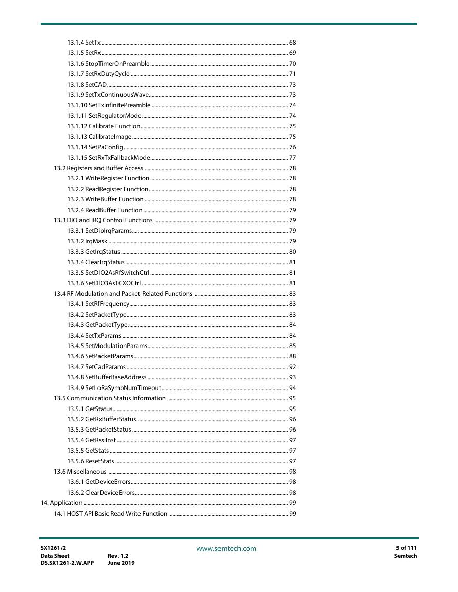
13.1.4 SetTx ...................................................................................................................................... 68 13.1.5 SetRx...................................................................................................................................... 69 13.1.6 StopTimerOnPreamble................................................................................................... 70 13.1.7 SetRxDutyCycle ................................................................................................................. 71 13.1.8 SetCAD.................................................................................................................................. 73 13.1.9 SetTxContinuousWave.................................................................................................... 73 13.1.10 SetTxInfinitePreamble .................................................................................................. 74 13.1.11 SetRegulatorMode......................................................................................................... 74 13.1.12 Calibrate Function.......................................................................................................... 75 13.1.13 CalibrateImage................................................................................................................ 75 13.1.14 SetPaConfig...................................................................................................................... 76 13.1.15 SetRxTxFallbackMode................................................................................................... 77 13.2 Registers and Buffer Access ....................................................................................................... 78 13.2.1 WriteRegister Function................................................................................................... 78 13.2.2 ReadRegister Function.................................................................................................... 78 13.2.3 WriteBuffer Function ....................................................................................................... 78 13.2.4 ReadBuffer Function........................................................................................................ 79 13.3 DIO and IRQ Control Functions ................................................................................................ 79 13.3.1 SetDioIrqParams................................................................................................................ 79 13.3.2 IrqMask ................................................................................................................................. 79 13.3.3 GetIrqStatus ........................................................................................................................ 80 13.3.4 ClearIrqStatus..................................................................................................................... 81 13.3.5 SetDIO2AsRfSwitchCtrl ................................................................................................... 81 13.3.6 SetDIO3AsTCXOCtrl ......................................................................................................... 81 13.4 RF Modulation and Packet-Related Functions ................................................................... 83 13.4.1 SetRfFrequency.................................................................................................................. 83 13.4.2 SetPacketType.................................................................................................................... 83 13.4.3 GetPacketType................................................................................................................... 84 13.4.4 SetTxParams ....................................................................................................................... 84 13.4.5 SetModulationParams..................................................................................................... 85 13.4.6 SetPacketParams............................................................................................................... 88 13.4.7 SetCadParams .................................................................................................................... 92 13.4.8 SetBufferBaseAddress ..................................................................................................... 93 13.4.9 SetLoRaSymbNumTimeout........................................................................................... 94 13.5 Communication Status Information ...................................................................................... 95 13.5.1 GetStatus.............................................................................................................................. 95 13.5.2 GetRxBufferStatus............................................................................................................. 96 13.5.3 GetPacketStatus ................................................................................................................ 96 13.5.4 GetRssiInst ........................................................................................................................... 97 13.5.5 GetStats ................................................................................................................................ 97 13.5.6 ResetStats ............................................................................................................................ 97 13.6 Miscellaneous ................................................................................................................................. 98 13.6.1 GetDeviceErrors................................................................................................................. 98 13.6.2 ClearDeviceErrors.............................................................................................................. 98 14. Application ................................................................................................................................................... 99 14.1 HOST API Basic Read Write Function ..................................................................................... 99 SX1261/2 Data Sheet DS.SX1261-2.W.APP Rev. 1.2 June 2019 www.semtech.com 5 of 111 Semtech
14.2 Circuit Configuration for Basic Tx Operation ...................................................................... 99 14.3 Circuit Configuration for Basic Rx Operation ....................................................................100 14.4 Issuing Commands in the Right Order ................................................................................100 14.5 Application Schematics ............................................................................................................101 14.5.1 Application Design of the SX1261 with RF Switch .............................................101 14.5.2 Application Design of the SX1262 with RF Switch .............................................101 15. Known Limitations...................................................................................................................................102 15.1 Modulation Quality with 500 kHz LoRa® Bandwidth .....................................................102 15.1.1 Description........................................................................................................................102 15.1.2 Workaround......................................................................................................................102 15.2 Better Resistance of the SX1262 Tx to Antenna Mismatch ..........................................102 15.2.1 Description........................................................................................................................102 15.2.2 Workaround......................................................................................................................103 15.3 Implicit Header Mode Timeout Behavior ...........................................................................103 15.3.1 Description........................................................................................................................103 15.3.2 Workaround......................................................................................................................103 15.4 Optimizing the Inverted IQ Operation ................................................................................103 15.4.1 Description........................................................................................................................103 15.4.2 Workaround......................................................................................................................104 16. Packaging Information...........................................................................................................................105 16.1 Package Outline Drawing ........................................................................................................105 16.2 Package Marking .........................................................................................................................106 16.3 Land Pattern .................................................................................................................................106 16.4 Reflow Profiles ..............................................................................................................................107 SX1261/2 Data Sheet DS.SX1261-2.W.APP Rev. 1.2 June 2019 www.semtech.com 6 of 111 Semtech
List of Figures Figure 2-1: SX1261/2 Top View Pin Location QFN 4x4 24L............................................................... 13 Figure 4-1: SX1261/2 Block Diagram......................................................................................................... 22 Figure 4-2: TCXO Control Block................................................................................................................... 24 Figure 4-3: PA Supply Scheme in DC-DC Mode .................................................................................... 27 Figure 4-4: VR_PA versus Output Power on the SX1261 ................................................................... 27 Figure 4-5: Current versus Output Power with DC-DC Regulation on the SX1261.................. 28 Figure 4-6: Current versus Output Power with LDO Regulation on the SX1261....................... 28 Figure 4-7: Power Linearity on the SX1261 with either LDO or DC-DC Regulation ................. 29 Figure 4-8: VR_PA versus Output Power on the SX1262 ................................................................... 29 Figure 4-9: Power Linearity on the SX1262............................................................................................. 30 Figure 4-10: Current versus Programmed Output Power on the SX1262 ................................... 30 Figure 5-1: SX1261 Diagram with the DC-DC Regulator Power Option....................................... 33 Figure 5-2: SX1261 Diagram with the LDO Regulator Power Option............................................ 34 Figure 5-3: SX1262 Diagram with the DC-DC Regulator Power Option....................................... 34 Figure 5-4: SX1262 Diagram with the LDO Regulator Power Option............................................ 35 Figure 5-5: Separate DIO Supply................................................................................................................. 36 Figure 6-1: LoRa® Signal Bandwidth.......................................................................................................... 38 Figure 6-2: LoRa® Packet Format ................................................................................................................ 40 Figure 6-3: Fixed-Length Packet Format ................................................................................................. 45 Figure 6-4: Variable-Length Packet Format............................................................................................ 45 Figure 6-5: Data Whitening LFSR................................................................................................................ 46 Figure 7-1: Data Buffer Diagram ................................................................................................................. 48 Figure 8-1: SPI Timing Diagram................................................................................................................... 50 Figure 8-2: SPI Timing Transition................................................................................................................ 51 Figure 8-3: Switching Time Definition...................................................................................................... 52 Figure 8-4: Switching Time Definition in Active Mode....................................................................... 53 Figure 9-1: Transceiver Circuit Modes ...................................................................................................... 60 Figure 13-1: Stopping Timer on Preamble or Header Detection.................................................... 71 Figure 13-2: RX Duty Cycle Energy Profile............................................................................................... 72 Figure 13-3: RX Duty Cycle when Receiving........................................................................................... 73 Figure 14-1: Application Schematic of the SX1261 with RF Switch............................................. 101 Figure 14-2: Application Schematic of the SX1262 with RF Switch............................................. 101 Figure 16-1: QFN 4x4 Package Outline Drawing................................................................................. 105 Figure 16-2: SX1261/2 Marking................................................................................................................. 106 Figure 16-3: QFN 4x4mm Land Pattern.................................................................................................. 106 SX1261/2 Data Sheet DS.SX1261-2.W.APP Rev. 1.2 June 2019 www.semtech.com 7 of 111 Semtech
List of Tables Table 2-1: SX1261/2 Pinout in QFN 4x4 24L ........................................................................................... 12 Table 3-1: ESD and Latch-up Notice.......................................................................................................... 14 Table 3-2: Absolute Maximum Ratings..................................................................................................... 14 Table 3-3: Operating Range.......................................................................................................................... 14 Table 3-4: Crystal Specifications ................................................................................................................. 15 Table 3-5: Power Consumption................................................................................................................... 16 Table 3-6: Power Consumption in Transmit Mode .............................................................................. 17 Table 3-7: General Specifications ............................................................................................................... 18 Table 3-8: Receive Mode Specifications................................................................................................... 19 Table 3-9: Transmit Mode Specifications................................................................................................. 21 Table 3-10: Digital I/O Specifications ........................................................................................................ 21 Table 4-1: Internal Foot Capacitor Configuration................................................................................. 23 Table 4-2: Intermediate Frequencies in FSK Mode .............................................................................. 25 Table 4-3: Intermediate Frequencies in LoRa® Mode.......................................................................... 26 Table 4-4: Power Amplifier Summary ....................................................................................................... 31 Table 5-1: Regulation Type versus Circuit Mode................................................................................... 32 Table 5-2: OCP Configuration ...................................................................................................................... 32 Table 5-3: Recommended 15 μH Inductors ............................................................................................ 35 Table 6-1: Range of Spreading Factors (SF) ............................................................................................ 38 Table 6-2: Signal Bandwidth Setting in LoRa® Mode........................................................................... 39 Table 6-3: Coding Rate Overhead .............................................................................................................. 39 Table 6-4: Bandwidth Definition in FSK Packet Type .......................................................................... 43 Table 6-5: Whitening Initial Value .............................................................................................................. 46 Table 6-6: CRC Type Configuration............................................................................................................ 47 Table 6-7: CRC Initial Value ........................................................................................................................... 47 Table 6-8: CRC Polynomial ............................................................................................................................ 47 Table 8-1: SPI Timing Requirements.......................................................................................................... 51 Table 8-2: Switching Time............................................................................................................................. 53 Table 8-3: Digital Pads Configuration for each Chip Mode............................................................... 54 Table 8-4: IRQ Status Registers.................................................................................................................... 55 Table 9-1: SX1261/2 Operating Modes..................................................................................................... 56 Table 9-2: Image Calibration Over the ISM Bands................................................................................ 57 Table 9-3: Rx Gain Configuration................................................................................................................ 58 Table 10-1: SPI Interface Command Sequence ..................................................................................... 61 Table 11-1: Commands Selecting the Operating Modes of the Radio ......................................... 62 Table 11-2: Commands to Access the Radio Registers and FIFO Buffer....................................... 63 Table 11-3: Commands Controlling the Radio IRQs and DIOs......................................................... 63 Table 11-4: Commands Controlling the RF and Packets Settings .................................................. 63 Table 11-5: Commands Returning the Radio Status............................................................................ 64 Table 12-1: List of Registers .......................................................................................................................... 65 Table 13-1: SetSleep SPI Transaction ........................................................................................................ 67 Table 13-2: Sleep Mode Definition............................................................................................................. 67 Table 13-3: SetConfig SPI Transaction...................................................................................................... 68 Table 13-4: STDBY Mode Configuration .................................................................................................. 68 Table 13-5: SetFs SPI Transaction ............................................................................................................... 68 Table 13-6: SetTx SPI Transaction............................................................................................................... 68 Table 13-7: SetTx Timeout Duration.......................................................................................................... 69 Table 13-8: SetRx SPI Transaction............................................................................................................... 69 Table 13-9: SetRx Timeout Duration ......................................................................................................... 70 Table 13-10: StopTimerOnPreamble SPI Transaction ......................................................................... 70 SX1261/2 Data Sheet DS.SX1261-2.W.APP Rev. 1.2 June 2019 www.semtech.com 8 of 111 Semtech
分享到:
收藏