logo资料库

LPS22HBTR数据手册(Lps22hb).pdf

第1页 / 共49页
第2页 / 共49页
第3页 / 共49页
第4页 / 共49页
第5页 / 共49页
第6页 / 共49页
第7页 / 共49页
第8页 / 共49页
资料共49页,剩余部分请下载后查看
Table 1. Device summary
1 Block diagrams
Figure 1. Device architecture block diagram
Figure 2. Digital logic
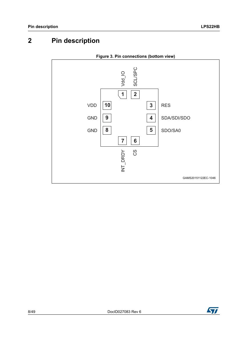
2 Pin description
Figure 3. Pin connections (bottom view)
Table 2. Pin description
3 Mechanical and electrical specifications
3.1 Mechanical characteristics
Table 3. Pressure and temperature sensor characteristics
3.2 Electrical characteristics
Table 4. Electrical characteristics
Table 5. DC characteristics
3.3 Communication interface characteristics
3.3.1 SPI - serial peripheral interface
Table 6. SPI slave timing values
Figure 4. SPI slave timing diagram
3.3.2 I2C - inter-IC control interface
Table 7. I2C slave timing values
Figure 5. I2C slave timing diagram
3.4 Absolute maximum ratings
Table 8. Absolute maximum ratings
4 Functionality
4.1 Sensing element
4.2 IC interface
4.3 Factory calibration
4.4 Interpreting pressure readings
Figure 6. Pressure readings
5 FIFO
5.1 Bypass mode
Figure 7. Bypass mode
5.2 FIFO mode
Figure 8. FIFO mode
5.3 Stream mode
Figure 9. Stream mode
5.4 Dynamic-Stream mode
Figure 10. Dynamic-Stream mode
5.5 Stream-to-FIFO mode
Figure 11. Stream-to-FIFO mode
5.6 Bypass-to-Stream mode
Figure 12. Bypass-to-Stream mode
5.7 Bypass-to-FIFO mode
Figure 13. Bypass-to-FIFO mode
5.8 Retrieving data from FIFO
6 Application hints
Figure 14. LPS22HB electrical connections (top view)
6.1 Soldering information
7 Digital interfaces
7.1 Serial interfaces
Table 9. Serial interface pin description
7.2 I2C serial interface (CS = High)
Table 10. I2C terminology
7.2.1 I2C operation
Table 11. SAD+Read/Write patterns
Table 12. Transfer when master is writing one byte to slave
Table 13. Transfer when master is writing multiple bytes to slave
Table 14. Transfer when master is receiving (reading) one byte of data from slave
Table 15. Transfer when master is receiving (reading) multiple bytes of data from slave
7.3 SPI bus interface
Figure 15. Read and write protocol
7.3.1 SPI read
Figure 16. SPI read protocol
Figure 17. Multiple byte SPI read protocol (2-byte example)
7.3.2 SPI write
Figure 18. SPI write protocol
Figure 19. Multiple byte SPI write protocol (2-byte example)
7.3.3 SPI read in 3-wire mode
Figure 20. SPI read protocol in 3-wire mode
8 Register mapping
Table 16. Registers address map
9 Register description
9.1 INTERRUPT_CFG (0Bh)
Figure 21. “Threshold based” interrupt event
9.2 THS_P_L (0Ch)
9.3 THS_P_H (0Dh)
9.4 WHO_AM_I (0Fh)
9.5 CTRL_REG1 (10h)
Table 17. Output data rate bit configurations
Table 18. Low-pass filter configurations
9.6 CTRL_REG2 (11h)
9.7 CTRL_REG3 (12h)
Table 19. Interrupt configurations
Figure 22. Interrupt events on INT_DRDY pin
9.8 FIFO_CTRL (14h)
Table 20. FIFO mode selection
9.9 REF_P_XL (15h)
9.10 REF_P_L (16h)
9.11 REF_P_H (17h)
9.12 RPDS_L (18h)
9.13 RPDS_H (19h)
9.14 RES_CONF (1Ah)
9.15 INT_SOURCE (25h)
9.16 FIFO_STATUS (26h)
Table 21. FIFO_STATUS example: OVR/FSS details
9.17 STATUS (27h)
9.18 PRESS_OUT_XL (28h)
9.19 PRESS_OUT_L (29h)
9.20 PRESS_OUT_H (2Ah)
9.21 TEMP_OUT_L (2Bh)
9.22 TEMP_OUT_H (2Ch)
9.23 LPFP_RES (33h)
10 Package information
10.1 HLGA-10L package information
Figure 23. HLGA-10L (2.0 x 2.0 x 0.76 mm typ.) package outline and mechanical dimensions
11 Revision history
Table 22. Document revision history
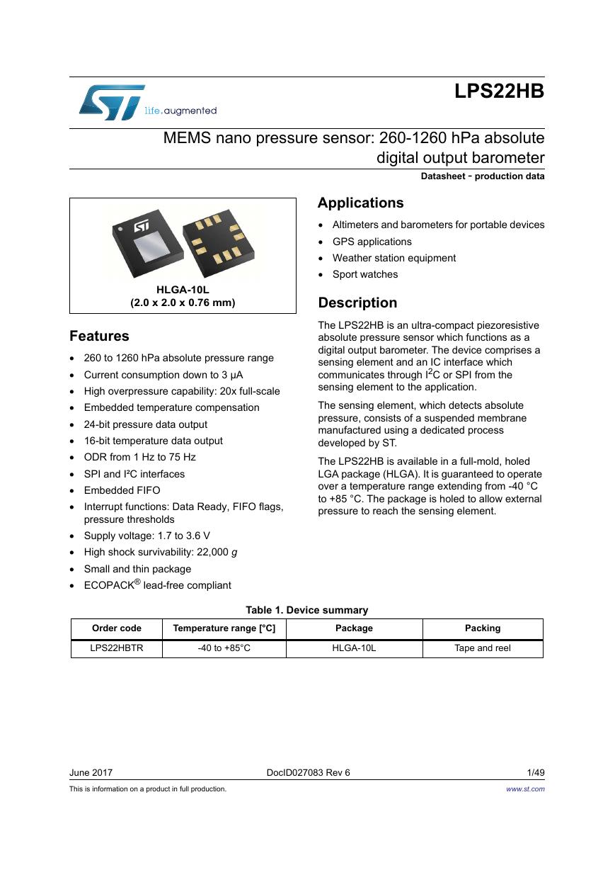
LPS22HB MEMS nano pressure sensor: 260-1260 hPa absolute digital output barometer Datasheet - production data Applications  Altimeters and barometers for portable devices  GPS applications  Weather station equipment  Sport watches Description The LPS22HB is an ultra-compact piezoresistive absolute pressure sensor which functions as a digital output barometer. The device comprises a sensing element and an IC interface which communicates through I2C or SPI from the sensing element to the application. The sensing element, which detects absolute pressure, consists of a suspended membrane manufactured using a dedicated process developed by ST. The LPS22HB is available in a full-mold, holed LGA package (HLGA). It is guaranteed to operate over a temperature range extending from -40 °C to +85 °C. The package is holed to allow external pressure to reach the sensing element. HLGA-10L (2.0 x 2.0 x 0.76 mm) Features  260 to 1260 hPa absolute pressure range  Current consumption down to 3 μA  High overpressure capability: 20x full-scale  Embedded temperature compensation  24-bit pressure data output  16-bit temperature data output  ODR from 1 Hz to 75 Hz  SPI and I²C interfaces  Embedded FIFO  Interrupt functions: Data Ready, FIFO flags, pressure thresholds  Supply voltage: 1.7 to 3.6 V  High shock survivability: 22,000 g  Small and thin package  ECOPACK® lead-free compliant Order code LPS22HBTR Temperature range [°C] Table 1. Device summary Package -40 to +85°C HLGA-10L Packing Tape and reel June 2017 This is information on a product in full production. DocID027083 Rev 6 1/49 www.st.com
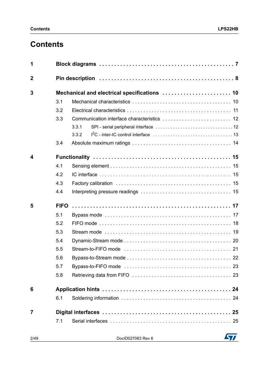
Contents Contents LPS22HB 1 2 3 4 5 6 7 Block diagrams . . . . . . . . . . . . . . . . . . . . . . . . . . . . . . . . . . . . . . . . . . . . . 7 Pin description . . . . . . . . . . . . . . . . . . . . . . . . . . . . . . . . . . . . . . . . . . . . . 8 Mechanical and electrical specifications . . . . . . . . . . . . . . . . . . . . . . . 10 3.1 Mechanical characteristics . . . . . . . . . . . . . . . . . . . . . . . . . . . . . . . . . . . . 10 Electrical characteristics . . . . . . . . . . . . . . . . . . . . . . . . . . . . . . . . . . . . . . 11 3.2 Communication interface characteristics . . . . . . . . . . . . . . . . . . . . . . . . . 12 3.3 3.3.1 SPI - serial peripheral interface . . . . . . . . . . . . . . . . . . . . . . . . . . . . . . . 12 I2C - inter-IC control interface . . . . . . . . . . . . . . . . . . . . . . . . . . . . . . . . 13 3.3.2 Absolute maximum ratings . . . . . . . . . . . . . . . . . . . . . . . . . . . . . . . . . . . . 14 3.4 Functionality . . . . . . . . . . . . . . . . . . . . . . . . . . . . . . . . . . . . . . . . . . . . . . 15 4.1 Sensing element . . . . . . . . . . . . . . . . . . . . . . . . . . . . . . . . . . . . . . . . . . . . 15 IC interface . . . . . . . . . . . . . . . . . . . . . . . . . . . . . . . . . . . . . . . . . . . . . . . . 15 4.2 Factory calibration . . . . . . . . . . . . . . . . . . . . . . . . . . . . . . . . . . . . . . . . . . 15 4.3 4.4 Interpreting pressure readings . . . . . . . . . . . . . . . . . . . . . . . . . . . . . . . . . 15 FIFO . . . . . . . . . . . . . . . . . . . . . . . . . . . . . . . . . . . . . . . . . . . . . . . . . . . . . 17 5.1 Bypass mode . . . . . . . . . . . . . . . . . . . . . . . . . . . . . . . . . . . . . . . . . . . . . . 17 FIFO mode . . . . . . . . . . . . . . . . . . . . . . . . . . . . . . . . . . . . . . . . . . . . . . . . 18 5.2 Stream mode . . . . . . . . . . . . . . . . . . . . . . . . . . . . . . . . . . . . . . . . . . . . . . 19 5.3 5.4 Dynamic-Stream mode . . . . . . . . . . . . . . . . . . . . . . . . . . . . . . . . . . . . . . . 20 Stream-to-FIFO mode . . . . . . . . . . . . . . . . . . . . . . . . . . . . . . . . . . . . . . . 21 5.5 5.6 Bypass-to-Stream mode . . . . . . . . . . . . . . . . . . . . . . . . . . . . . . . . . . . . . . 22 Bypass-to-FIFO mode . . . . . . . . . . . . . . . . . . . . . . . . . . . . . . . . . . . . . . . 23 5.7 5.8 Retrieving data from FIFO . . . . . . . . . . . . . . . . . . . . . . . . . . . . . . . . . . . . 23 Application hints . . . . . . . . . . . . . . . . . . . . . . . . . . . . . . . . . . . . . . . . . . . 24 6.1 Soldering information . . . . . . . . . . . . . . . . . . . . . . . . . . . . . . . . . . . . . . . . 24 Digital interfaces . . . . . . . . . . . . . . . . . . . . . . . . . . . . . . . . . . . . . . . . . . . 25 7.1 Serial interfaces . . . . . . . . . . . . . . . . . . . . . . . . . . . . . . . . . . . . . . . . . . . . 25 2/49 DocID027083 Rev 6
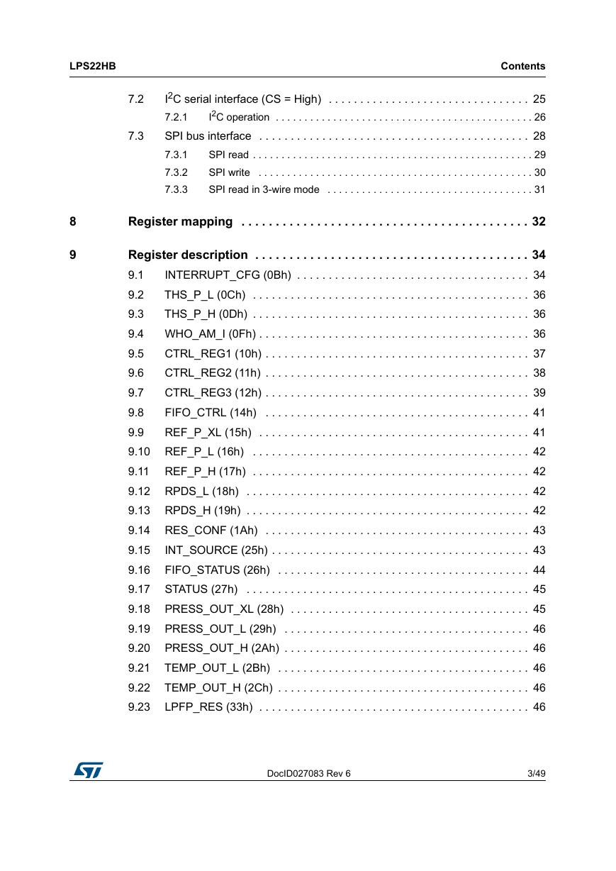
LPS22HB Contents 8 9 7.2 7.3 I2C serial interface (CS = High) . . . . . . . . . . . . . . . . . . . . . . . . . . . . . . . . 25 I2C operation . . . . . . . . . . . . . . . . . . . . . . . . . . . . . . . . . . . . . . . . . . . . . 26 7.2.1 SPI bus interface . . . . . . . . . . . . . . . . . . . . . . . . . . . . . . . . . . . . . . . . . . . 28 SPI read . . . . . . . . . . . . . . . . . . . . . . . . . . . . . . . . . . . . . . . . . . . . . . . . . 29 7.3.1 SPI write . . . . . . . . . . . . . . . . . . . . . . . . . . . . . . . . . . . . . . . . . . . . . . . . 30 7.3.2 7.3.3 SPI read in 3-wire mode . . . . . . . . . . . . . . . . . . . . . . . . . . . . . . . . . . . . 31 Register mapping . . . . . . . . . . . . . . . . . . . . . . . . . . . . . . . . . . . . . . . . . . 32 Register description . . . . . . . . . . . . . . . . . . . . . . . . . . . . . . . . . . . . . . . . 34 INTERRUPT_CFG (0Bh) . . . . . . . . . . . . . . . . . . . . . . . . . . . . . . . . . . . . . 34 9.1 9.2 THS_P_L (0Ch) . . . . . . . . . . . . . . . . . . . . . . . . . . . . . . . . . . . . . . . . . . . . 36 9.3 THS_P_H (0Dh) . . . . . . . . . . . . . . . . . . . . . . . . . . . . . . . . . . . . . . . . . . . . 36 9.4 WHO_AM_I (0Fh) . . . . . . . . . . . . . . . . . . . . . . . . . . . . . . . . . . . . . . . . . . . 36 CTRL_REG1 (10h) . . . . . . . . . . . . . . . . . . . . . . . . . . . . . . . . . . . . . . . . . . 37 9.5 CTRL_REG2 (11h) . . . . . . . . . . . . . . . . . . . . . . . . . . . . . . . . . . . . . . . . . . 38 9.6 9.7 CTRL_REG3 (12h) . . . . . . . . . . . . . . . . . . . . . . . . . . . . . . . . . . . . . . . . . . 39 FIFO_CTRL (14h) . . . . . . . . . . . . . . . . . . . . . . . . . . . . . . . . . . . . . . . . . . 41 9.8 9.9 REF_P_XL (15h) . . . . . . . . . . . . . . . . . . . . . . . . . . . . . . . . . . . . . . . . . . . 41 9.10 REF_P_L (16h) . . . . . . . . . . . . . . . . . . . . . . . . . . . . . . . . . . . . . . . . . . . . 42 9.11 REF_P_H (17h) . . . . . . . . . . . . . . . . . . . . . . . . . . . . . . . . . . . . . . . . . . . . 42 9.12 RPDS_L (18h) . . . . . . . . . . . . . . . . . . . . . . . . . . . . . . . . . . . . . . . . . . . . . 42 9.13 RPDS_H (19h) . . . . . . . . . . . . . . . . . . . . . . . . . . . . . . . . . . . . . . . . . . . . . 42 9.14 RES_CONF (1Ah) . . . . . . . . . . . . . . . . . . . . . . . . . . . . . . . . . . . . . . . . . . 43 9.15 INT_SOURCE (25h) . . . . . . . . . . . . . . . . . . . . . . . . . . . . . . . . . . . . . . . . . 43 9.16 FIFO_STATUS (26h) . . . . . . . . . . . . . . . . . . . . . . . . . . . . . . . . . . . . . . . . 44 9.17 STATUS (27h) . . . . . . . . . . . . . . . . . . . . . . . . . . . . . . . . . . . . . . . . . . . . . 45 9.18 PRESS_OUT_XL (28h) . . . . . . . . . . . . . . . . . . . . . . . . . . . . . . . . . . . . . . 45 9.19 PRESS_OUT_L (29h) . . . . . . . . . . . . . . . . . . . . . . . . . . . . . . . . . . . . . . . 46 9.20 PRESS_OUT_H (2Ah) . . . . . . . . . . . . . . . . . . . . . . . . . . . . . . . . . . . . . . . 46 TEMP_OUT_L (2Bh) . . . . . . . . . . . . . . . . . . . . . . . . . . . . . . . . . . . . . . . . 46 9.21 TEMP_OUT_H (2Ch) . . . . . . . . . . . . . . . . . . . . . . . . . . . . . . . . . . . . . . . . 46 9.22 9.23 LPFP_RES (33h) . . . . . . . . . . . . . . . . . . . . . . . . . . . . . . . . . . . . . . . . . . . 46 DocID027083 Rev 6 3/49 49
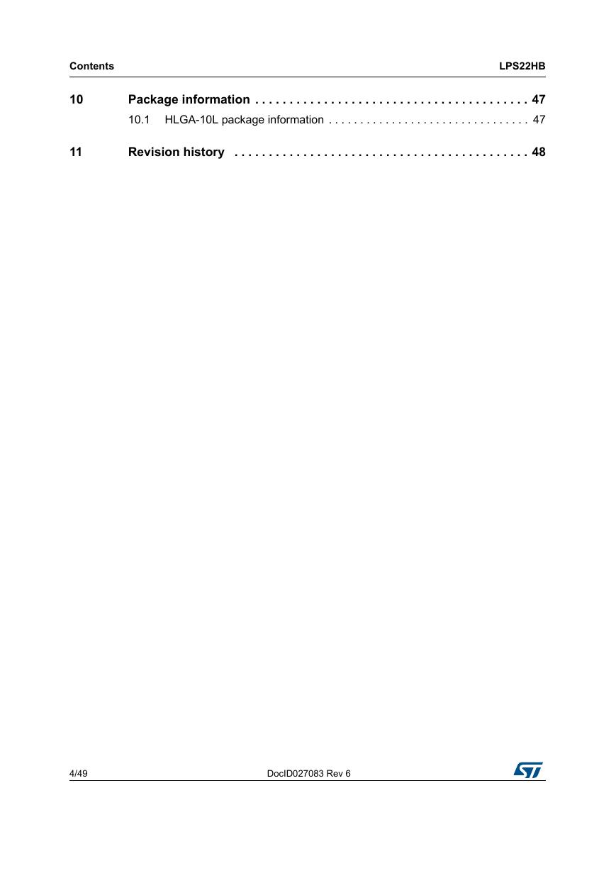
Contents 10 11 Package information . . . . . . . . . . . . . . . . . . . . . . . . . . . . . . . . . . . . . . . . 47 10.1 HLGA-10L package information . . . . . . . . . . . . . . . . . . . . . . . . . . . . . . . . 47 Revision history . . . . . . . . . . . . . . . . . . . . . . . . . . . . . . . . . . . . . . . . . . . 48 LPS22HB 4/49 DocID027083 Rev 6
LPS22HB List of tables List of tables Device summary . . . . . . . . . . . . . . . . . . . . . . . . . . . . . . . . . . . . . . . . . . . . . . . . . . . . . . . . . . 1 Table 1. Pin description . . . . . . . . . . . . . . . . . . . . . . . . . . . . . . . . . . . . . . . . . . . . . . . . . . . . . . . . . . . 9 Table 2. Pressure and temperature sensor characteristics . . . . . . . . . . . . . . . . . . . . . . . . . . . . . . . 10 Table 3. Electrical characteristics . . . . . . . . . . . . . . . . . . . . . . . . . . . . . . . . . . . . . . . . . . . . . . . . . . . 11 Table 4. DC characteristics. . . . . . . . . . . . . . . . . . . . . . . . . . . . . . . . . . . . . . . . . . . . . . . . . . . . . . . . 11 Table 5. SPI slave timing values. . . . . . . . . . . . . . . . . . . . . . . . . . . . . . . . . . . . . . . . . . . . . . . . . . . . 12 Table 6. I2C slave timing values . . . . . . . . . . . . . . . . . . . . . . . . . . . . . . . . . . . . . . . . . . . . . . . . . . . . 13 Table 7. Absolute maximum ratings . . . . . . . . . . . . . . . . . . . . . . . . . . . . . . . . . . . . . . . . . . . . . . . . . 14 Table 8. Serial interface pin description . . . . . . . . . . . . . . . . . . . . . . . . . . . . . . . . . . . . . . . . . . . . . . 25 Table 9. I2C terminology . . . . . . . . . . . . . . . . . . . . . . . . . . . . . . . . . . . . . . . . . . . . . . . . . . . . . . . . . . 25 Table 10. SAD+Read/Write patterns . . . . . . . . . . . . . . . . . . . . . . . . . . . . . . . . . . . . . . . . . . . . . . . . . 26 Table 11. Transfer when master is writing one byte to slave . . . . . . . . . . . . . . . . . . . . . . . . . . . . . . . 26 Table 12. Transfer when master is writing multiple bytes to slave . . . . . . . . . . . . . . . . . . . . . . . . . . . 27 Table 13. Transfer when master is receiving (reading) one byte of data from slave . . . . . . . . . . . . . 27 Table 14. Transfer when master is receiving (reading) multiple bytes of data from slave . . . . . . . . . 27 Table 15. Table 16. Registers address map. . . . . . . . . . . . . . . . . . . . . . . . . . . . . . . . . . . . . . . . . . . . . . . . . . . . 32 Table 17. Output data rate bit configurations . . . . . . . . . . . . . . . . . . . . . . . . . . . . . . . . . . . . . . . . . . . 37 Low-pass filter configurations . . . . . . . . . . . . . . . . . . . . . . . . . . . . . . . . . . . . . . . . . . . . . . . 38 Table 18. Interrupt configurations . . . . . . . . . . . . . . . . . . . . . . . . . . . . . . . . . . . . . . . . . . . . . . . . . . . . 40 Table 19. FIFO mode selection. . . . . . . . . . . . . . . . . . . . . . . . . . . . . . . . . . . . . . . . . . . . . . . . . . . . . . 41 Table 20. Table 21. FIFO_STATUS example: OVR/FSS details . . . . . . . . . . . . . . . . . . . . . . . . . . . . . . . . . . . . 44 Document revision history. . . . . . . . . . . . . . . . . . . . . . . . . . . . . . . . . . . . . . . . . . . . . . . . . . 48 Table 22. DocID027083 Rev 6 5/49 49
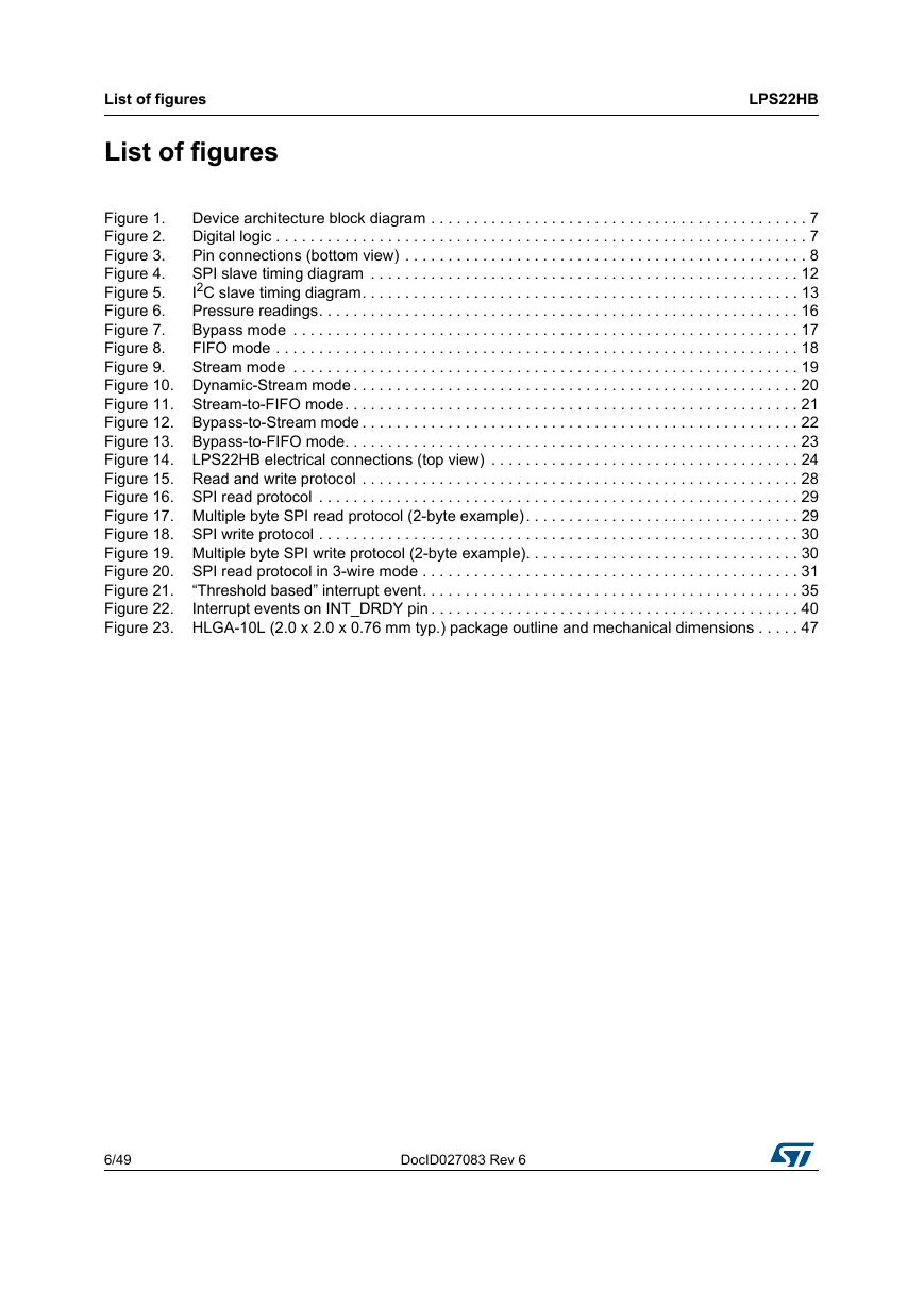
List of figures List of figures LPS22HB Device architecture block diagram . . . . . . . . . . . . . . . . . . . . . . . . . . . . . . . . . . . . . . . . . . . . 7 Figure 1. Digital logic . . . . . . . . . . . . . . . . . . . . . . . . . . . . . . . . . . . . . . . . . . . . . . . . . . . . . . . . . . . . . . 7 Figure 2. Pin connections (bottom view) . . . . . . . . . . . . . . . . . . . . . . . . . . . . . . . . . . . . . . . . . . . . . . . 8 Figure 3. SPI slave timing diagram . . . . . . . . . . . . . . . . . . . . . . . . . . . . . . . . . . . . . . . . . . . . . . . . . . 12 Figure 4. I2C slave timing diagram. . . . . . . . . . . . . . . . . . . . . . . . . . . . . . . . . . . . . . . . . . . . . . . . . . . 13 Figure 5. Pressure readings. . . . . . . . . . . . . . . . . . . . . . . . . . . . . . . . . . . . . . . . . . . . . . . . . . . . . . . . 16 Figure 6. Bypass mode . . . . . . . . . . . . . . . . . . . . . . . . . . . . . . . . . . . . . . . . . . . . . . . . . . . . . . . . . . . 17 Figure 7. FIFO mode . . . . . . . . . . . . . . . . . . . . . . . . . . . . . . . . . . . . . . . . . . . . . . . . . . . . . . . . . . . . . 18 Figure 8. Figure 9. Stream mode . . . . . . . . . . . . . . . . . . . . . . . . . . . . . . . . . . . . . . . . . . . . . . . . . . . . . . . . . . . 19 Figure 10. Dynamic-Stream mode . . . . . . . . . . . . . . . . . . . . . . . . . . . . . . . . . . . . . . . . . . . . . . . . . . . . 20 Figure 11. Stream-to-FIFO mode. . . . . . . . . . . . . . . . . . . . . . . . . . . . . . . . . . . . . . . . . . . . . . . . . . . . . 21 Figure 12. Bypass-to-Stream mode . . . . . . . . . . . . . . . . . . . . . . . . . . . . . . . . . . . . . . . . . . . . . . . . . . . 22 Figure 13. Bypass-to-FIFO mode. . . . . . . . . . . . . . . . . . . . . . . . . . . . . . . . . . . . . . . . . . . . . . . . . . . . . 23 Figure 14. LPS22HB electrical connections (top view) . . . . . . . . . . . . . . . . . . . . . . . . . . . . . . . . . . . . 24 Figure 15. Read and write protocol . . . . . . . . . . . . . . . . . . . . . . . . . . . . . . . . . . . . . . . . . . . . . . . . . . . 28 Figure 16. SPI read protocol . . . . . . . . . . . . . . . . . . . . . . . . . . . . . . . . . . . . . . . . . . . . . . . . . . . . . . . . 29 Figure 17. Multiple byte SPI read protocol (2-byte example). . . . . . . . . . . . . . . . . . . . . . . . . . . . . . . . 29 Figure 18. SPI write protocol . . . . . . . . . . . . . . . . . . . . . . . . . . . . . . . . . . . . . . . . . . . . . . . . . . . . . . . . 30 Figure 19. Multiple byte SPI write protocol (2-byte example). . . . . . . . . . . . . . . . . . . . . . . . . . . . . . . . 30 Figure 20. SPI read protocol in 3-wire mode . . . . . . . . . . . . . . . . . . . . . . . . . . . . . . . . . . . . . . . . . . . . 31 Figure 21. “Threshold based” interrupt event. . . . . . . . . . . . . . . . . . . . . . . . . . . . . . . . . . . . . . . . . . . . 35 Figure 22. Interrupt events on INT_DRDY pin . . . . . . . . . . . . . . . . . . . . . . . . . . . . . . . . . . . . . . . . . . . 40 Figure 23. HLGA-10L (2.0 x 2.0 x 0.76 mm typ.) package outline and mechanical dimensions . . . . . 47 6/49 DocID027083 Rev 6
LPS22HB 1 Block diagrams Block diagrams Figure 1. Device architecture block diagram Figure 2. Digital logic DocID027083 Rev 6 7/49 49
Pin description 2 Pin description LPS22HB Figure 3. Pin connections (bottom view) 8/49 DocID027083 Rev 6
分享到:
收藏