OPTICAL SENSOR
LTR-390UV-01
Description
Features
The LTR-390UV-01 is an integrated low voltage I2C ambient
I2C interface capable of Standard mode @100kHz or
logic
Fast mode @400kHz communication; 1.8V
light sensor (ALS) and ultraviolet light sensor (UVS) in a single
compatible
miniature 2x2mm chipled lead-free surface mount package.
Ambient Light / Ultraviolet light (UVS) Technology in one
This sensor converts light intensity to a digital output signal
ultra-small 2x2mm ChipLED package
capable of direct I2C interface. It provides a linear ALS
Very low power consumption with sleep mode capability
response over a wide dynamic range, and is well suited to
Operating voltage ranges: 1.7V to 3.6V
applications under high ambient brightness.
Operating temperature ranges: -40 to +85 ºC
The sensor has a programmable interrupt with hysteresis to
response to events and that removes the need to poll the
Built-in temperature compensation circuit
Programmable interrupt function for ALS , UVS with
upper and lower thresholds
sensor for a reading which improves system efficiency. This
CMOS design and factory-set one time trimming capability
ensure minimal sensor-to-sensor variations
for ease of
manufacturability to the end customers.
Application
RoHS and Halogen free compliant
UVS/ALS Features
13 to 20 bits effective resolution
Wide dynamic range of 1:18,000,000 with linear
response
Close to human eye spectral response
Automatic
rejection
for 50Hz/60Hz
lighting
Identifying the UV index in ambient light helps people to
flicker
effectively protect themselves from sunburns, cancer or
eye damage.
To control brightness and color of the display panel in
mobile, computing, and consumer devices.
Ordering Information
Part Number
Packaging Type
Package
LTR-390UV-01
Tape and Reel
6-pin chipled package
Quantity
2500
1/33
Part No. : LTR-390UV-01
BNS-OD-FC002/A4
�
1.
Outline Dimensions
OPTICAL SENSOR
LTR-390UV-01
2/33
Part No. : LTR-390UV-01
BNS-OD-FC002/A4
�
Functional Block Diagram
2.
OPTICAL SENSOR
LTR-390UV-01
LTR-390UV-01 contains 2 integrated photodiodes (ALS/UVS) for respective photocurrent measurements. The
photodiode currents are converted to digital values by ADCs. The sensor also includes some peripheral circuits such as
an internal oscillator and voltage reference.
3/33
Part No. : LTR-390UV-01
BNS-OD-FC002/A4
�
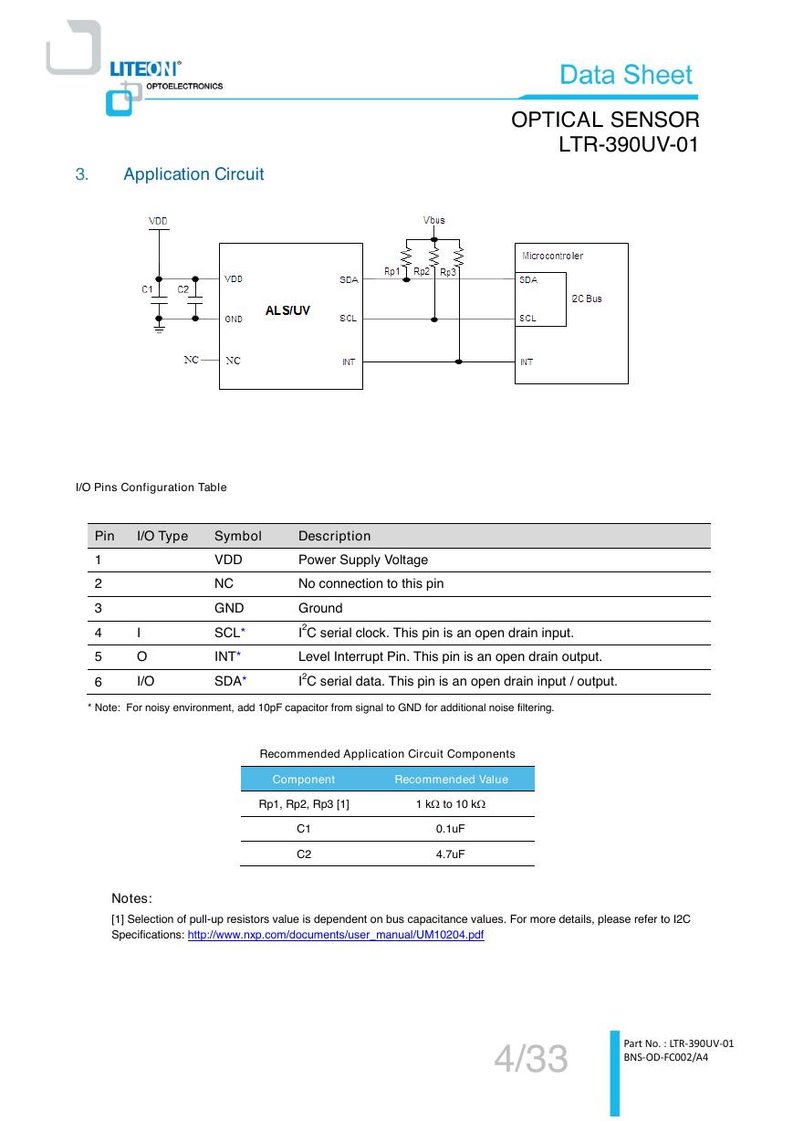
3.
Application Circuit
OPTICAL SENSOR
LTR-390UV-01
I/O Pins Configuration Table
Pin
I/O Type
Symbol
Description
1
2
3
4
5
6
I
O
I/O
VDD
NC
GND
SCL*
INT*
SDA*
Power Supply Voltage
No connection to this pin
Ground
I2C serial clock. This pin is an open drain input.
Level Interrupt Pin. This pin is an open drain output.
I2C serial data. This pin is an open drain input / output.
* Note: For noisy environment, add 10pF capacitor from signal to GND for additional noise filtering.
Recommended Application Circuit Components
Component
Recommended Value
Rp1, Rp2, Rp3 [1]
1 k to 10 k
C1
C2
0.1uF
4.7uF
Notes:
[1] Selection of pull-up resistors value is dependent on bus capacitance values. For more details, please refer to I2C
Specifications: http://www.nxp.com/documents/user_manual/UM10204.pdf
4/33
Part No. : LTR-390UV-01
BNS-OD-FC002/A4
�
OPTICAL SENSOR
LTR-390UV-01
Rating and Specification
4.1. Absolute Maximum Rating at Ta=25°C
Parameter
Supply Voltage
Symbol
VDD
Digital Voltage Range
SCL, SDA, INT
Storage Temperature
Tstg
Max. Input Current
SCL,SDA,INT
Electrostatic Discharge Protection
(Human Body Model JESD22-A114)
VHBM
Min.
-0.5
-100
Max.
Unit
4.0
4.0
-45 to 95
100
2000
V
V
C
mA
V
Note: Exceeding these ratings could cause damage to the sensor. All voltages are with respect to ground.
Currents are positive into, negative out of the specified terminal.
4.2. Recommended Operating Conditions
Description
Supply Voltage
Interface signal input high
Interface signal input low
Operating Temperature
Symbol
Min.
Typ.
Max.
Unit
VDD
VI2Chigh
VI2Clow
Tope
1.7
1.5
0
-40
3.6
VDD
0.4
85
V
V
V
C
4.3. Electrical Specifications (VDD = 2.8V, Ta=25°C, unless otherwise noted)
Parameter
Min.
Typ.
Max.
Unit
Condition
ALS Active Mode Current
UVS Active Mode Current
Standby Current
Wakeup Time from Standby
110
100
200
1
5
10
10
uA
uA
uA
ms
Max. duty cycle, Vdd=2.8V,
Gain 3x
Max. duty cycle, Vdd=2.8V
Standby / Sleep Mode
From Standby to Active mode
where measurement can start
4.
5/33
Part No. : LTR-390UV-01
BNS-OD-FC002/A4
�
OPTICAL SENSOR
LTR-390UV-01
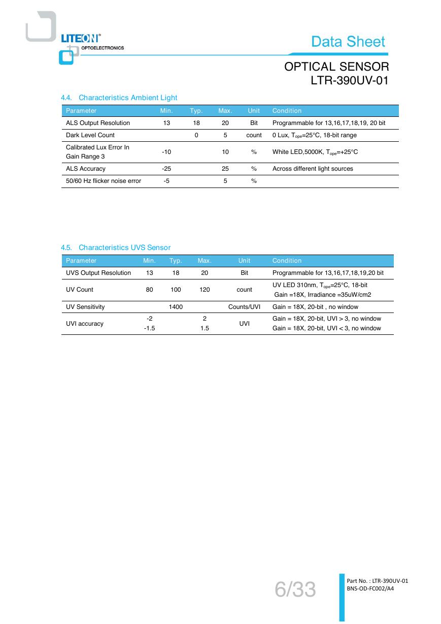
4.4. Characteristics Ambient Light
Parameter
Min.
Typ.
Max.
Unit
Condition
ALS Output Resolution
Dark Level Count
Calibrated Lux Error In
Gain Range 3
ALS Accuracy
50/60 Hz flicker noise error
13
-10
-25
-5
18
0
20
5
10
25
5
Bit
Programmable for 13,16,17,18,19, 20 bit
count
0 Lux, Tope=25°C, 18-bit range
%
%
%
White LED,5000K, Tope=+25°C
Across different light sources
4.5. Characteristics UVS Sensor
Parameter
Min.
Typ.
Max.
UVS Output Resolution
13
18
20
Unit
Bit
UV Count
80
100
120
count
Condition
Programmable for 13,16,17,18,19,20 bit
UV LED 310nm, Tope=25°C, 18-bit
Gain =18X, Irradiance =35uW/cm2
UV Sensitivity
1400
UVI accuracy
-2
-1.5
2
1.5
Counts/UVI
Gain = 18X, 20-bit , no window
UVI
Gain = 18X, 20-bit, UVI > 3, no window
Gain = 18X, 20-bit, UVI < 3, no window
6/33
Part No. : LTR-390UV-01
BNS-OD-FC002/A4
�
OPTICAL SENSOR
LTR-390UV-01
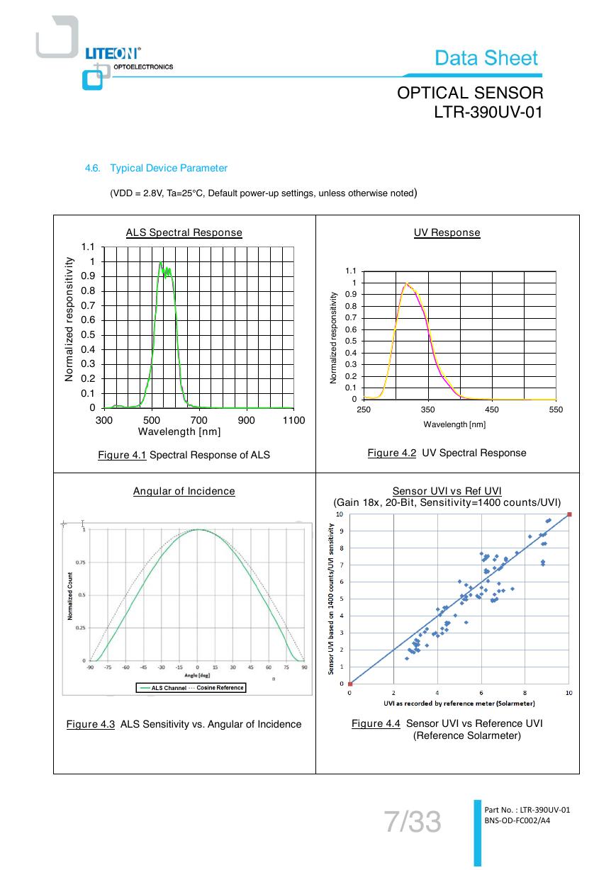
4.6. Typical Device Parameter
(VDD = 2.8V, Ta=25°C, Default power-up settings, unless otherwise noted)
ALS Spectral Response
UV Response
y
t
i
v
i
t
i
s
n
o
p
s
e
r
d
e
z
i
l
a
m
r
o
N
1.1
1
0.9
0.8
0.7
0.6
0.5
0.4
0.3
0.2
0.1
0
300
500
700
900
1100
Wavelength [nm]
Figure 4.1 Spectral Response of ALS
Angular of Incidence
y
t
i
v
i
t
i
s
n
o
p
s
e
r
d
e
z
i
l
a
m
r
o
N
1.1
1
0.9
0.8
0.7
0.6
0.5
0.4
0.3
0.2
0.1
0
250
350
450
550
Wavelength [nm]
Figure 4.2 UV Spectral Response
Sensor UVI vs Ref UVI
(Gain 18x, 20-Bit, Sensitivity=1400 counts/UVI)
Figure 4.3 ALS Sensitivity vs. Angular of Incidence
Figure 4.4 Sensor UVI vs Reference UVI
(Reference Solarmeter)
7/33
Part No. : LTR-390UV-01
BNS-OD-FC002/A4
�
OPTICAL SENSOR
LTR-390UV-01
4.8. AC Electrical Characteristics
All specifications are at VBus = 1.7V, Tope = 25C, unless otherwise noted.
Parameter
Symbol
Standard (Min)
Fast (Min)
Unit
SCL clock frequency
Bus free time between a STOP and START
condition
Hold time (repeated) START condition. After this
period, the first clock pulse is generated
LOW period of the SCL clock
HIGH period of the SCL clock
Set-up time for a repeated START condition
Set-up time for STOP condition
Rise time of both SDA and SCL signals
Fall time of both SDA and SCL signals
Data hold time
Data setup time
Pulse width of spikes which must be suppressed by
the input filter
100
400
KHz
4.7
4
4.7
4
4.7
4
30
30
0
100
0
300
300
100
50
us
us
us
us
us
us
ns
ns
us
ns
ns
Definition of timing for I2C bus
8/33
Part No. : LTR-390UV-01
BNS-OD-FC002/A4
SCLfBUFtSTAHDt;LOWtHIGHtSTASUt;STOSUt;rtftDATHDt;DATSUt;SPt�


 V2版本原理图(Capacitive-Fingerprint-Reader-Schematic_V2).pdf
 摄像头工作原理.doc
 VL53L0X简要说明(En.FLVL53L00216).pdf
 原理图(DVK720-Schematic).pdf
 原理图(Pico-Clock-Green-Schdoc).pdf
 原理图(RS485-CAN-HAT-B-schematic).pdf
 File:SIM7500_SIM7600_SIM7800 Series_SSL_Application Note_V2.00.pdf
 ADS1263(Ads1262).pdf
 原理图(Open429Z-D-Schematic).pdf
 用户手册(Capacitive_Fingerprint_Reader_User_Manual_CN).pdf
 CY7C68013A(英文版)(CY7C68013A).pdf
 TechnicalReference_Dem.pdf