Preliminary Datasheet SGP40
Indoor Air Quality Sensor for VOC Measurements
MOx based gas sensor for indoor air quality applications
Outstanding long-term stability and lifetime
I2C interface with digital output signal
Very small 6-pin DFN package: 2.44 x 2.44 x 0.85 mm3
Low power consumption: 2.6 mA at 3.3 V
Tape and reel packaged, reflow solderable
VOC Algorithm feature an unmatched robustness
against contaminating gases present in real-world
applications enabling a unique long-term stability as
well as low drift and device-to-device variation. The very
small 2.44 x 2.44 x 0.85 mm3 DFN package enables
applications
Sensirion’s
state-of-the-art production process guarantees high
reproducibility and reliability. Tape and reel packaging
together with suitability for standard SMD assembly
processes make the SGP40 predestined for high-
volume applications.
spaces.
in
limited
Product Summary
The SGP40 is a digital gas sensor designed for easy
integration
into air purifiers or demand-controlled
ventilation systems. Sensirion’s CMOSens® technology
offers a complete, easy-to-use sensor system on a single
chip featuring a digital I2C interface and a temperature-
controlled micro hotplate, providing a humidity-
compensated VOC based indoor air quality signal. The
output signal can be directly processed by Sensirion’s
powerful VOC Algorithm to translate the raw signal into a
VOC Index as a robust measure for indoor air quality. The
VOC Algorithm automatically adapts to the environment
the sensor is exposed to. Both sensing element and
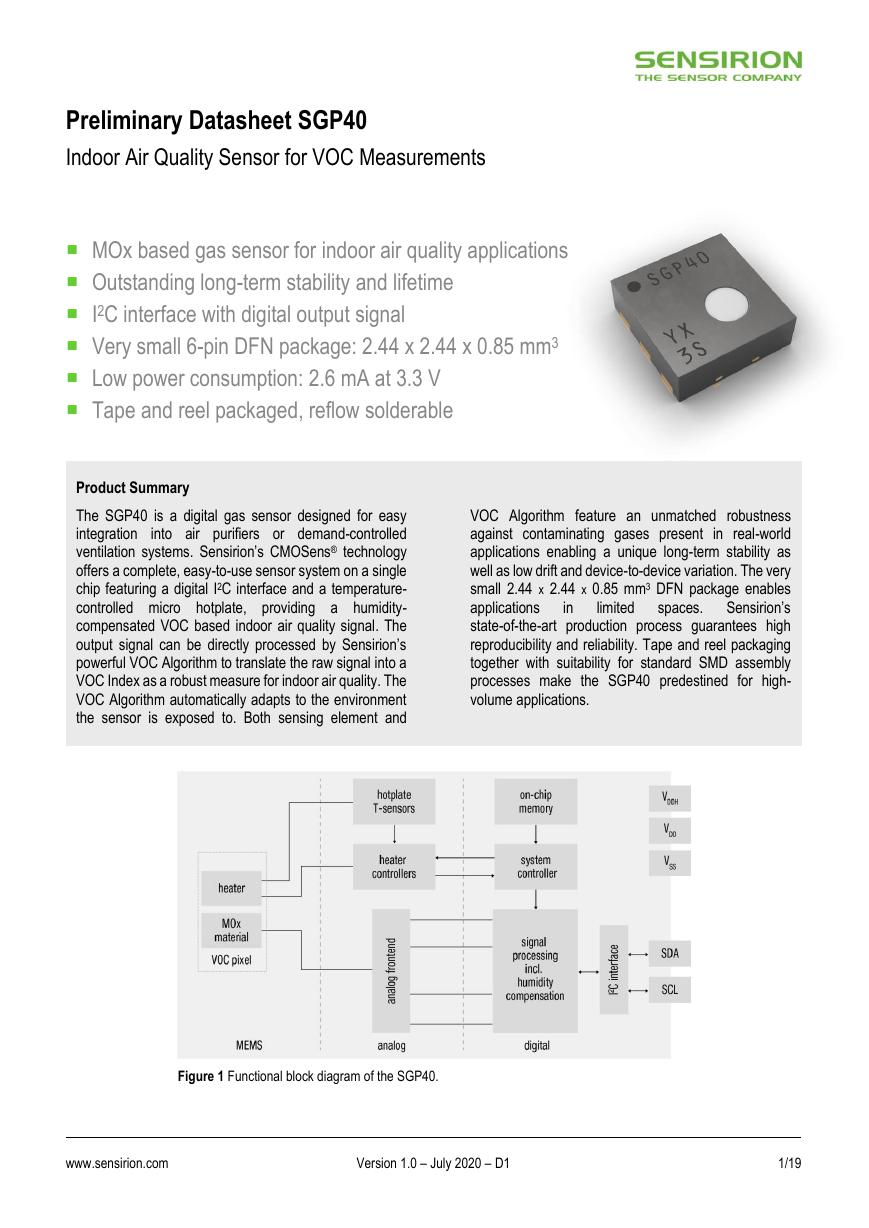
Figure 1 Functional block diagram of the SGP40.
www.sensirion.com
Version 1.0 – July 2020 – D1
1/19
�
Table of Contents
1 Sensor Performance .................................................................................................................................................................. 3
2 Specifications............................................................................................................................................................................. 5
3 Sensor Output Signal Description .............................................................................................................................................. 9
4 Digital Interface Description ..................................................................................................................................................... 11
5 Mechanical Specifications ....................................................................................................................................................... 15
6 Ordering Information ................................................................................................................................................................ 17
www.sensirion.com
Version 1.0 – July 2020 – D1
2/19
�
1 Sensor Performance
Table 1 lists specifications characterizing the gas sensing performance. The SGP40 chip provides a digital raw signal (SRAW)
which is sensitive to all VOC gases typically present in indoor environments and which is proportional to the logarithm of the
resistance of the MOx material. This signal is intended for further processing by an algorithm providing quantitative information
about the VOC based indoor air quality. For this purpose, Sensirion offers its robust VOC Algorithm, which is included in the
VOC Index driver package available on Sensirion’s webpage.1 The algorithm maps all VOC and fresh air events to a VOC Index
scale (see application note SGP40 – VOC Index for Experts for more details). For the specifications given below, ethanol in
clean air has been used as proxy gas for typical indoor air events.
Parameter
Comments
Output signals3
Digital processed value (VOC Index)
Digital raw value (SRAW)
Measurement range Ethanol in clean air
Specified range
Ethanol in clear air
Device-to-device
variation
VOC Index5
Repeatability
VOC Index5
Limit of detection6,7
Ethanol in specified range
Response time
Changing concentration
from 5 to 10 ppm of ethanol, at
sampling interval of 1 s
63
90
Switch-on behavior
Time until reliably detecting VOC events8
Sensitivity7
Time until specifications in this table are
met
SRAW,
doubling VOC
concentration
Ethanol in specified
range
5 to 10 ppm of
ethanol
Recommended
sampling interval
VOC Index
SRAW
Values2
Min.
Typ.
0
0
0
0.3
–
–
–
–
–
–
–
–
–
–
–
–
<±15
<±15
<±5
<±5
–
<10
<30
<60
<1
−870
Max.
500
65’535
1’000
30
–
–
<50
<10
–
–
–
–
–
Units
VOC Index points
ticks4
ppm
ppm
VOC Index points
or
% VOC Index m.v.
(the larger)
VOC Index points
or
% VOC Index m.v.
(the larger)
ppb
or
% of concentration setpoint
(the larger)
s
s
s
h
ticks
−710
−870
−1’030
ticks
–
10
1
1
–
0.5
s
s
Table 1 Gas sensing specifications at 25 °C and 50 % RH in zero air (considered as clean air for indoor air quality applications) and a power
supply of VDD of 3.3 V. All concentrations refer to ethanol as test gas.
1 Download the VOC Index Driver Package SGP40 on https://www.sensirion.com/en/download-center/gas-sensors/multi-pixel-gas-sensors/.
2 99.99 % of the sensors will be within the minimum–maximum tolerance corresponding to 4σ assuming a normal distribution. Typical tolerance refers to the mean of the
distribution for ≥100 sensors.
3 Humidity compensated when actual humidity value is provided as input to the sensor (see section 3.1 Raw Signal Measurement).
4 Signal in ticks is proportional to the logarithm of the resistance of the sensing layer.
5 Evaluated using the calibration and test sequence according to the application note SGP40 – Testing Guide.
6 Limit of detection is defined as the minimum change of concentration required to obtain a raw signal change 3 times higher than the noise at the given concentration setpoint.
7 Parameter tested over simulated lifetime of 10 years in an indoor environment. Test conditions: continuous operation in 250 ppm of Decamethylcyclopentasiloxane (D5).
8 Signal increase during 60-s event of 5 to 10 ppm of ethanol is three times larger than signal drift without this event during the same duration.
www.sensirion.com
Version 1.0 – July 2020 – D1
3/19
�
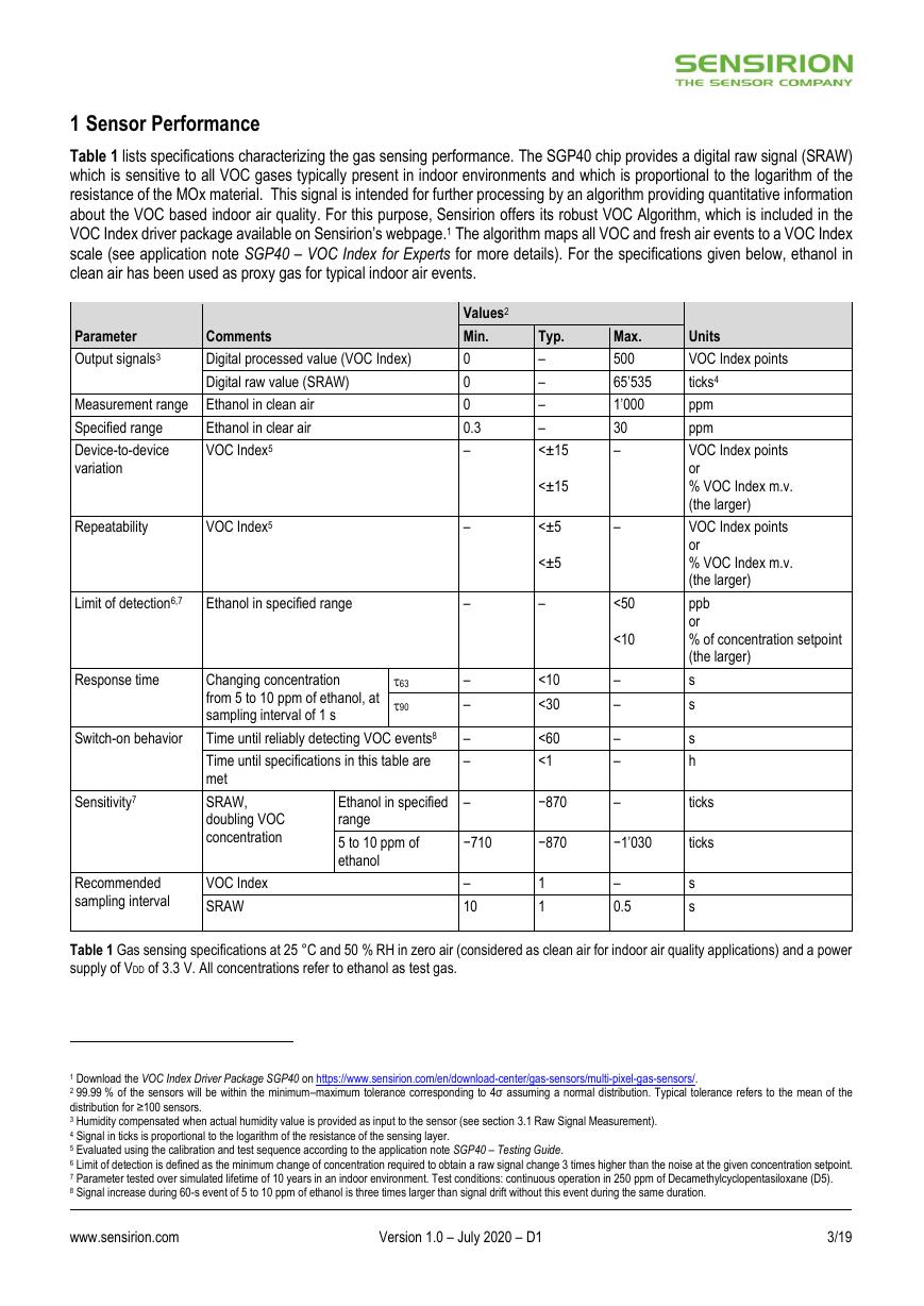
Figure 2 displays the typical response of the raw signal of SGP40 to various VOCs as a function of their concentrations in
otherwise clean air.
Figure 2 Typical sensor response to various VOCs normalized to
500 ppb of ethanol. Data were recorded at 25 °C and 50 % RH and
a power supply of VDD of 3.3 V.
www.sensirion.com
Version 1.0 – July 2020 – D1
4/19
�
2 Specifications
2.1 Electrical Specifications
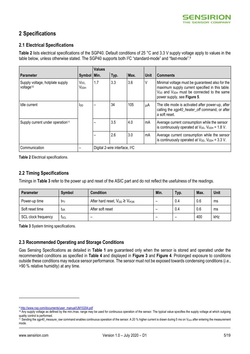
Table 2 lists electrical specifications of the SGP40. Default conditions of 25 °C and 3.3 V supply voltage apply to values in the
table below, unless otherwise stated. The SGP40 supports both I2C “standard-mode” and “fast-mode”.9
Parameter
Supply voltage, hotplate supply
voltage10
Values
Symbol
Min.
VDD,
VDDH
1.7
Typ.
3.3
Idle current
IDD
–
34
105
A
Max.
Unit Comments
3.6
V
Minimal voltage must be guaranteed also for the
maximum supply current specified in this table.
VDD and VDDH must be connected to the same
power supply, see Figure 5.
The idle mode is activated after power-up, after
calling the sgp40_heater_off command, or after
a soft reset.
Supply current under operation11
–
–
3.5
4.0
mA
Average current consumption while the sensor
is continuously operated at VDD, VDDH = 1.8 V.
2.6
3.0
mA
Average current consumption while the sensor
is continuously operated at VDD, VDDH = 3.3 V.
Communication
–
Digital 2-wire interface, I2C
Table 2 Electrical specifications.
2.2 Timing Specifications
Timings in Table 3 refer to the power up and reset of the ASIC part and do not reflect the usefulness of the readings.
Parameter
Symbol
Condition
Min.
Typ.
Max.
Unit
Power-up time
Soft reset time
tPU
tSR
After hard reset, VDD ≥ VPOR
After soft reset
SCL clock frequency
fSCL
–
Table 3 System timing specifications.
–
–
–
0.4
0.4
–
0.6
0.6
400
ms
ms
kHz
2.3 Recommended Operating and Storage Conditions
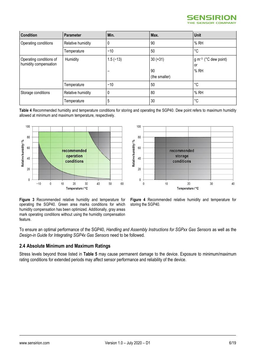
Gas Sensing Specifications as detailed in Table 1 are guaranteed only when the sensor is stored and operated under the
recommended conditions as specified in Table 4 and displayed in Figure 3 and Figure 4. Prolonged exposure to conditions
outside these conditions may reduce sensor performance. The sensor must not be exposed towards condensing conditions (i.e.,
>90 % relative humidity) at any time.
9 http://www.nxp.com/documents/user_manual/UM10204.pdf
10 Any supply voltage as defined by the min./max. range may be used for continuous operation of the sensor. The typical value specifies the supply voltage at which outgoing
quality control is performed.
11 Sending the sgp40_measure_raw command enables continuous operation of the sensor. A 20 % higher current is drawn during 5 ms on VDDH after entering the measurement
mode.
www.sensirion.com
Version 1.0 – July 2020 – D1
5/19
�
Condition
Parameter
Operating conditions
Relative humidity
Operating conditions of
humidity compensation
Temperature
Humidity
Temperature
Storage conditions
Relative humidity
Temperature
Min.
0
−10
1.5 (−13)
–
−10
0
5
Max.
90
50
30 (+31)
90
(the smaller)
50
80
30
Unit
% RH
°C
g m−3 (°C dew point)
or
% RH
°C
% RH
°C
Table 4 Recommended humidity and temperature conditions for storing and operating the SGP40. Dew point refers to maximum humidity
allowed at minimum and maximum temperature, respectively.
Figure 3 Recommended relative humidity and temperature for
operating the SGP40. Green area marks conditions for which
humidity compensation has been optimized. Additionally, gray areas
mark operating conditions without using the humidity compensation
feature.
Figure 4 Recommended relative humidity and temperature for
storing the SGP40.
To ensure an optimal performance of the SGP40, Handling and Assembly Instructions for SGPxx Gas Sensors as well as the
Design-in Guide for Integrating SGP4x Gas Sensors need to be followed.
2.4 Absolute Minimum and Maximum Ratings
Stress levels beyond those listed in Table 5 may cause permanent damage to the device. Exposure to minimum/maximum
rating conditions for extended periods may affect sensor performance and reliability of the device.
www.sensirion.com
Version 1.0 – July 2020 – D1
6/19
�
Parameter
Supply voltage VDD
Supply voltage VDDH
Short-term storage temperature range12
Operating temperature range
Rating
−0.3 to +3.6 V
−0.3 to +3.6 V
−40 to +70 °C
−20 to +55 °C
Short-term storage humidity range12
0 to 80 % (non-condensing)
Operating humidity range
0 to 90 % (non-condensing)
ESD HBM
ESD CDM
Latch up, JESD78 Class II, 125 °C
Table 5 Absolute minimum and maximum ratings.
2.5 Interface Specifications
2 kV
500 V
100 mA
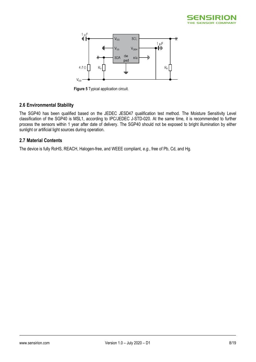
The SGP40 comes in a 6-pin DFN package, see Table 6. Figure 5 shows a typical application circuit. The VDD pin must be
decoupled with an RC element. The required decoupling for VDDH depends on the power supply network connected to the sensor,
a capacitor of 1 F is recommended. VDD and VDDH must be connected to one single supply VDD. The external pull-up resistors
(e.g., Rp = 10 k) are required to pull the SDA and SCL signal lines high. For dimensioning resistor sizes please take bus
capacity and communication frequency into account (see section 7.1 of NXPs I2C Manual for more details, see footnote 9 on
page 5). It should be noted that pull-up resistors may be included in I/O circuits of microcontrollers. The die pad or center pad is
electrically connected to GND. Hence, electrical considerations do not impose constraints on the wiring of the die pad. However,
for mechanical stability it is recommended to solder the die pad to the PCB.
Pin
Name
Comments
1
2
3
4
5
6
VDD
VSS
SDA
n/a
VDDH
SCL
Supply voltage
Ground
Serial data, bidirectional
Connect to ground (no electrical function)
Supply voltage, hotplate
Serial clock, bidirectional
Table 6 Pin assignment (transparent top view). Dashed lines are only visible from the bottom.
12 Short-term storage refers to temporary conditions during, e.g., transport.
www.sensirion.com
Version 1.0 – July 2020 – D1
7/19
�
Figure 5 Typical application circuit.
2.6 Environmental Stability
The SGP40 has been qualified based on the JEDEC JESD47 qualification test method. The Moisture Sensitivity Level
classification of the SGP40 is MSL1, according to IPC/JEDEC J-STD-020. At the same time, it is recommended to further
process the sensors within 1 year after date of delivery. The SGP40 should not be exposed to bright illumination by either
sunlight or artificial light sources during operation.
2.7 Material Contents
The device is fully RoHS, REACH, Halogen-free, and WEEE compliant, e.g., free of Pb, Cd, and Hg.
www.sensirion.com
Version 1.0 – July 2020 – D1
8/19
�



 V2版本原理图(Capacitive-Fingerprint-Reader-Schematic_V2).pdf
 摄像头工作原理.doc
 VL53L0X简要说明(En.FLVL53L00216).pdf
 原理图(DVK720-Schematic).pdf
 原理图(Pico-Clock-Green-Schdoc).pdf
 原理图(RS485-CAN-HAT-B-schematic).pdf
 File:SIM7500_SIM7600_SIM7800 Series_SSL_Application Note_V2.00.pdf
 ADS1263(Ads1262).pdf
 原理图(Open429Z-D-Schematic).pdf
 用户手册(Capacitive_Fingerprint_Reader_User_Manual_CN).pdf
 CY7C68013A(英文版)(CY7C68013A).pdf
 TechnicalReference_Dem.pdf