�
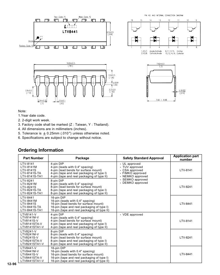
Note:
1.Year date code.
2. 2-digit work week.
3. Factory code shall be marked (Z : Taiwan, Y : Thailand).
4. All dimensions are in millimeters (inches).
5. Tolerance is
6. Specifications are subject to change without notice.
0.25mm (.010 ) unless otherwise noted.
Ordering Information
Part Number
LTV-8141
LTV-8141M
LTV-8141S
LTV-8141S-TA
LTV-8141S-TA1
LTV-8241
LTV-8241M
LTV-8241S
LTV-8241S-TA
LTV-8241S-TA1
LTV-8441
LTV-8441M
LTV-8441S
LTV-8441S-TA
LTV-8441S-TA1
LTV8141-V
LTV8141M-V
LTV8141S-V
LTV8141STA-V
LTV8141STA1-V
LTV8241-V
LTV8241M-V
LTV8241S-V
LTV8241STA-V
LTV8241STA1-V
LTV8441-V
LTV8441M-V
LTV8441S-V
LTV8441STA-V
LTV8441STA1-V
12-96
Package
Safety Standard Approval
Application part
number
UL approved
TUV approved
CSA approved
FIMKO approved
NEMKO approved
SEMKO approved
DEMKO approved
VDE approved
4-pin DIP
4-pin (leads with 0.4" spacing)
4-pin (lead bends for surface mount)
4-pin (tape and reel packaging of type I)
4-pin (tape and reel packaging of type II)
8-pin DIP
8-pin (leads with 0.4" spacing)
8-pin (lead bends for surface mount)
8-pin (tape and reel packaging of type I)
8-pin (tape and reel packaging of type II)
16-pin DIP
16-pin (leads with 0.4" spacing)
16-pin (lead bends for surface mount)
16-pin (tape and reel packaging of type I)
16-pin (tape and reel packaging of type II)
LTV-8141
LTV-8241
LTV-8441
LTV-8141
LTV-8241
LTV-8441
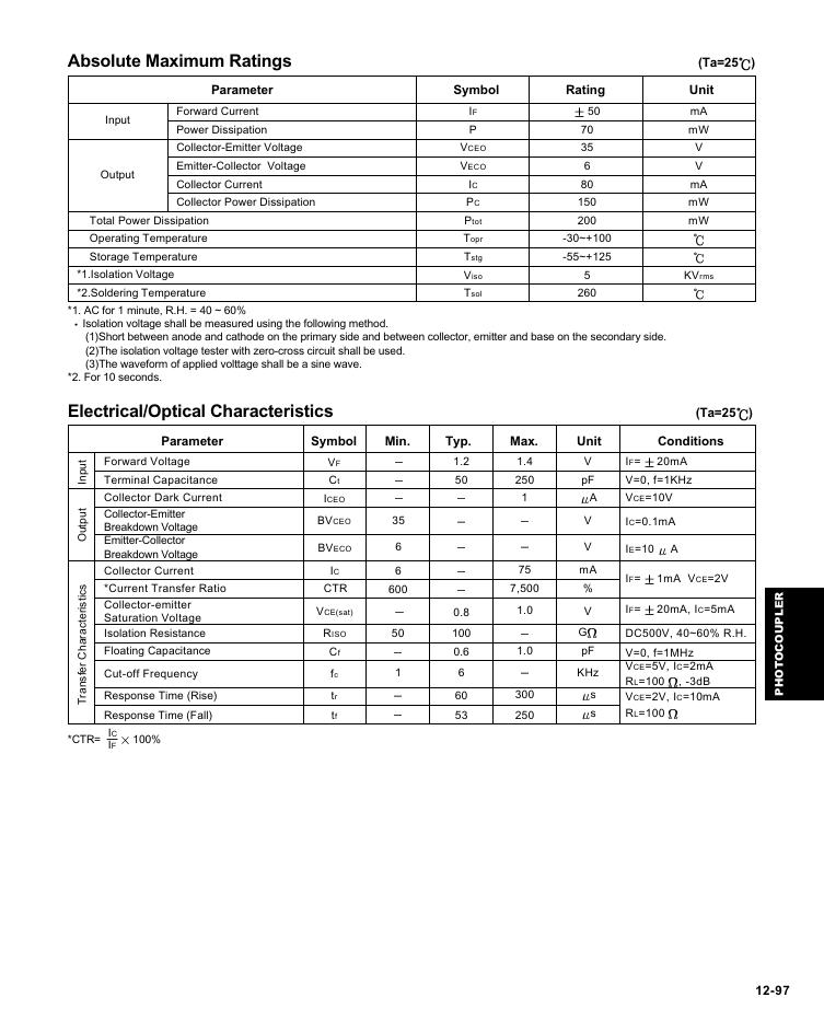
Absolute Maximum Ratings (Ta=25 )
Input
Output
Parameter
Forward Current
Power Dissipation
Collector-Emitter Voltage
Emitter-Collector Voltage
Collector Current
Collector Power Dissipation
Total Power Dissipation
Operating Temperature
Storage Temperature
*1.Isolation Voltage
*2.Soldering Temperature
Symbol Rating Unit
mA
mW
IF
P
V
V
mA
mW
mW
KVrms
-30~+100
-55~+125
5
260
50
70
35
6
80
150
200
VCEO
VECO
IC
PC
Ptot
Topr
Tstg
Viso
Tsol
Isolation voltage shall be measured using the following method.
*1. AC for 1 minute, R.H. = 40 ~ 60%
(1)Short between anode and cathode on the primary side and between collector, emitter and base on the secondary side.
(2)The isolation voltage tester with zero-cross circuit shall be used.
(3)The waveform of applied volttage shall be a sine wave.
*2. For 10 seconds.
Electrical/Optical Characteristics (Ta=25 )
Parameter Symbol Min. Typ. Max. Unit Conditions
t
u
p
n
I
t
u
p
t
u
O
s
c
i
t
s
i
r
e
t
c
a
r
a
h
C
r
e
f
s
n
a
r
T
*CTR=
Forward Voltage
Terminal Capacitance
Collector Dark Current
Collector-Emitter
Breakdown Voltage
Emitter-Collector
Breakdown Voltage
Collector Current
*Current Transfer Ratio
Collector-emitter
Saturation Voltage
Isolation Resistance
Floating Capacitance
Cut-off Frequency
Response Time (Rise)
Response Time (Fall)
IC
IF
100%
VF
Ct
ICEO
BVCEO
BVECO
IC
CTR
VCE(sat)
RISO
Cf
fc
tr
tf
35
6
6
600
50
1
1.2
50
0.8
100
0.6
6
60
53
1.4
250
1
75
7,500
1.0
1.0
300
250
V
pF
A
V
V
mA
%
V
G
pF
KHz
s
s
IF=
20mA
V=0, f=1KHz
VCE=10V
IC=0.1mA
IE=10
A
IF=
1mA VCE=2V
IF=
20mA, IC=5mA
DC500V, 40~60% R.H.
V=0, f=1MHz
VCE=5V, IC=2mA
RL=100
, -3dB
VCE=2V, IC=10mA
RL=100
R
E
L
P
U
O
C
O
T
O
H
P
12-97
�
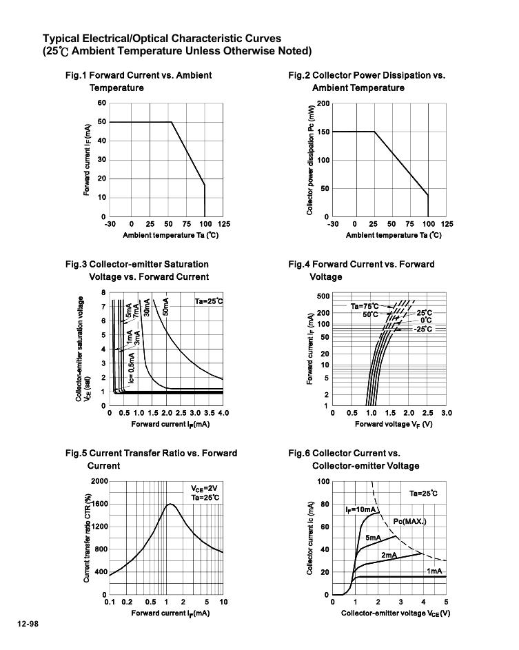
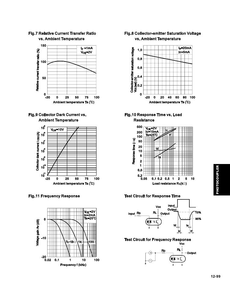
Typical Electrical/Optical Characteristic Curves
(25 Ambient Temperature Unless Otherwise Noted)
12-98
�
R
E
L
P
U
O
C
O
T
O
H
P
12-99
�


 V2版本原理图(Capacitive-Fingerprint-Reader-Schematic_V2).pdf
 摄像头工作原理.doc
 VL53L0X简要说明(En.FLVL53L00216).pdf
 原理图(DVK720-Schematic).pdf
 原理图(Pico-Clock-Green-Schdoc).pdf
 原理图(RS485-CAN-HAT-B-schematic).pdf
 File:SIM7500_SIM7600_SIM7800 Series_SSL_Application Note_V2.00.pdf
 ADS1263(Ads1262).pdf
 原理图(Open429Z-D-Schematic).pdf
 用户手册(Capacitive_Fingerprint_Reader_User_Manual_CN).pdf
 CY7C68013A(英文版)(CY7C68013A).pdf
 TechnicalReference_Dem.pdf