logo资料库

NV3030B(NV3030B_datasheet_V0.6_20220118).pdf

第1页 / 共246页
第2页 / 共246页
第3页 / 共246页
第4页 / 共246页
第5页 / 共246页
第6页 / 共246页
第7页 / 共246页
第8页 / 共246页
资料共246页,剩余部分请下载后查看
1.Introduction
2.Features
3.Block Diagram
4.Pin Function
4.1Power Supply Pins
4.2Interface Logic Pins
4.3Driver Output Pins
4.4Test and other pins
5.Pad Arrangement
5.1Output Bump Dimension
5.2Input Bump Dimension
5.3Alignment Mark Dimension
5.4Chip Information
6 PAD CENTER COORDINATES
7.Command
7.1Public command
7.1.1no operation (00h)
7.1.2read display ID (04h)
7.1.3read display status (09h)
7.1.4read display power mode (0Ah)
7.1.5read display MADCTL (0Bh)
7.1.6read display pixel format (0Ch)
7.1.7read display image mode (0Dh)
7.1.8read display signal mode (0Eh)
7.1.9read display self-diagnostic result (0Fh)
7.1.10sleep in (10h)
7.1.11sleep out (11h)
7.1.12partial mode on (12h)
7.1.13normal mode on and partial mode off (13h)
7.1.14display inversion off (20h)
7.1.15display inversion on (21h)
7.1.16display off (28h)
7.1.17display on (29h)
7.1.18column address (2Ah)
7.1.19page address (2Bh)
7.1.20memory write (2Ch)
7.1.21partial area (30h)
7.1.22vertical scrolling (33h)
7.1.23tearing effect line off (34h)
7.1.24tearing effect line on (35h)
7.1.25MADCTL(memory data access control) (36h)
7.1.26vertical scrolling start address (37h)
7.1.27idle mode off (38h)
7.1.28idle mode on and other mode off (39h)
7.1.29pixel format (3Ah)
7.1.30write memory continue (3Ch)
7.1.31set tear scanline (44h)
7.1.32get tear scan line (45h)
7.1.33write display brightess (53h)
7.1.34read display brightess (54h)
7.1.35read idd3 (D3h)
7.1.36read display id 1 (DAh)
7.1.37read display id 2 (DBh)
7.1.38read display id 3 (DCh)
7.2Private command
7.2.1osc setting (60h)
7.2.2dvdd setting (61h)
7.2.3bias setting (62h)
7.2.4vgl setting(63h)
7.2.5vgh setting (64h)
7.2.6vsp setting (65h)
7.2.7vsn setting (66h)
7.2.8pump clock sel (67h)
7.2.9gamma ref 1 (68h)
7.2.10OTP setting (6ch)
7.2.11lvd setting (6dh)
7.2.12RGB interface control (B0h)
7.2.13frame rate (B1h)
7.2.14display pol control (B4h)
7.2.15blanking porch (B5h)
7.2.16display function (B6h)
7.2.17entry mode set (B7h)
7.2.18OTP_CTRL0 (C2h)
7.2.19OTP_CTRL1 (C3h)
7.2.20 OTP_CTRL2 (C4h)
7.2.21 OTP_CTRL3(C6h)
7.2.22 OTP_CTRL4 (C7h)
7.2.23 OTP_CTRL5(C8h)
7.2.24 OTP_CTRL8 (C9h)
7.2.25 OTP_CTRL6(CAh)
7.2.26gamma positive 1 (E0h)
7.2.27gamma positive 2 (E1h)
7.2.28gamma positive 3 (E2h)
7.2.29gamma negative 1 (E3h)
7.2.30gamma negative 2 (E4h)
7.2.31gamma negative 3 (E5h)
7.2.32SRC_CTRL1 (E6h)
7.2.33SRC_CTRL2 (E7h)
7.2.34SRC_CTRL3 (E8h)
7.2.35Charge Share (E9h)
7.2.36SRC_CTRL4 (EAh)
7.2.37Gate driver timing (ECh)
7.2.38tearing effect (F1h)
7.2.39led (F2h)
7.2.40tearing effect (F4h)
7.2.41Interface control (F6h)
7.2.42 color palette enable (FBh)
7.2.43 color palette data (FCh)
7.2.44Private access (FDh)
8.Functional description
8.1Interface
8.1.1Serial Interface
8.1.1.1Write Cycle Sequence
8.1.1.2Read Cycle Sequence
8.1.1.3Data Transfer Break and Recovery
8.1.1.4Data Transfer Pause
8.1.1.52 data lane serial interface
8.1.2Parallel Interface
8.1.2.1Write Cycle/Sequence
8.1.2.2Read Cycle/Sequence
8.1.2.3Display Module Data Transfer Break
8.1.2.4Display Module Data Transfer Pause
8.1.2.5Display Module Data Transfer Modes
8.1.2.5.1Method 1
8.1.2.5.2Method 2
8.1.3RGB Interface
8.1.3.1RGB interface Selection
8.1.3.2RGB Interface Definition
8.1.3.3RGB Interface Mode Selection
8.1.3.4RGB Interface Timing Diagram
8.2Display Data RAM
8.2.1Configuration
8.2.2Memory to Display Address Mapping
8.2.2.1Normal Display On or Partial Mode On, Vertical Scr
8.2.2.2Vertical Scroll Mode
8.2.2.3Vertical Scroll example
8.2.3MPU to memory write/read direction
8.3Display Data Format
8.3.13-wire Serial Interface
8.3.24-wire Serial Interface
8.3.32 data lane serial interface
8.3.4Parallel Interface
8.3.4.18080-Ⅰ series 8-bit Parallel Interface
8.3.4.1.116-bit/pixel
8.3.4.1.218-bit/pixel
8.3.4.28080-Ⅱ series 8-bit Parallel Interface
8.3.4.2.116-bit/pixel
8.3.4.2.218-bit/pixel
8.3.4.38080-Ⅰ series 16-Bit Parallel Interface
8.3.4.3.116-bit/pixel
8.3.4.3.2 18-bit/pixel(MDT[1:0]=”00b”)
8.3.4.3.3 18-bit/pixel(MDT[1:0]=”01b”)
8.3.4.3.4 18-bit/pixel(MDT[1:0]=”10b”)
8.3.4.3.5 18-bit/pixel (MDT[1:0]=”11b”)
8.3.4.48080-Ⅱ series 16-Bit Parallel Interface
8.3.4.4.116-bit/pixel
8.3.4.4.2 18-bit/pixel(MDT[1:0]=”00b”)
8.3.4.4.3 18-bit/pixel(MDT[1:0]=”01b”)
8.3.4.4.4 18-bit/pixel(MDT[1:0]=”10b”)
8.3.4.4.5 18-bit/pixel(MDT[1:0]=”11b”)
8.3.4.58080-Ⅰ series 9-Bit Parallel Interface
8.3.4.5.116-bit/pixel
8.3.4.5.2 18-bit/pixel(MDT[1:0]=”00b”)
8.3.4.5.3 18-bit/pixel(MDT[1:0]=”01b”)
8.3.4.68080-Ⅱ series 9-bit Parallel Interface
8.3.4.6.116-bit/pixel
8.3.4.6.2 18-bit/pixel(MDT[1:0]=”00b”)
8.3.4.6.3 18-bit/pixel(MDT[1:0]=”01b”)
8.3.4.78080-Ⅰ series 18-Bit Parallel Interface
8.3.4.7.116-bit/pixel
8.3.4.7.218-bit/pixel
8.3.4.88080-Ⅱ series 18-Bit Parallel Interface
8.3.4.8.116-bit/pixel
8.3.4.8.218-bit/pixel
8.3.4.9Read Memory Data Color Coding
8.3.4.9.18 Data Line Parallel Interface I
8.3.4.9.29 Data Line Parallel Interface I
8.3.4.9.316 Data Line Parallel Interface I
8.3.4.9.418 Data Line Parallel Interface I & II
8.3.5RGB Interface
8.3.5.116-bit RGB interface
8.3.5.218-bit RGB interface
8.3.5.36-bit RGB interface
8.4Tearing effect output line
8.4.1Tearing Effect line Modes
8.4.2Tearing Effect line Timings
8.5Power On/Off Sequence
8.5.1Power On/Off Sequence
8.5.1.1Case 1 – RESX line is held high or Unstable by MPU
8.5.1.2Case 2 – RESX line is held low by MPU at Power On
8.6Power Level Definition
8.6.1Power levels
8.6.2Power flow chart
8.78-color Display Mode
8.8Gamma Correction
8.8.1Gamma-characteristics adjustment registers
8.8.2Gamma resister stream
8.8.3Variable resister
8.8.4The grayscale levels are determined by the followi
8.9Voltage Generation
8.10Relationship about source voltage
8.11Applied Voltage to the TFT panel
8.12Reset Timing
9.Application
10.Electrical Characteristics
10.1Absolute Maximum Ratings
10.2DC Characteristic
10.3AC Characteristics
10.3.1Serial Interface Timing Characteristics (3/4-wire
10.3.2Parallel Interface Timing Characteristics(8080 ser
10.3.3RGB Interface Timing Characteristics
上海新相微电子股份有限公司 DATA SHEETNV3030B 240RGB x 320dot, 262,144-color TFT Controller Driver with Internal RAM Version 0.6 Jan. 10, 2022 Jan. 2022 Confidential Information Ver. 0.6
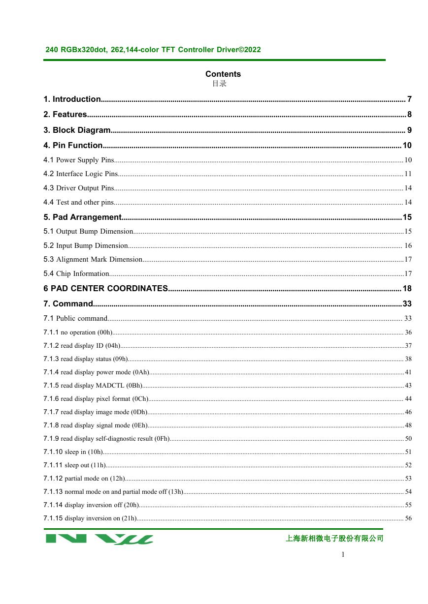
240 RGBx320dot, 262,144-color TFT Controller Driver©2022 Contents 目录 1. Introduction..................................................................................................................................................... 7 2. Features............................................................................................................................................................8 3. Block Diagram................................................................................................................................................ 9 4. Pin Function..................................................................................................................................................10 4.1 Power Supply Pins...........................................................................................................................................................10 4.2 Interface Logic Pins.........................................................................................................................................................11 4.3 Driver Output Pins...........................................................................................................................................................14 4.4 Test and other pins........................................................................................................................................................... 14 5. Pad Arrangement.........................................................................................................................................15 5.1 Output Bump Dimension.................................................................................................................................................15 5.2 Input Bump Dimension................................................................................................................................................... 16 5.3 Alignment Mark Dimension............................................................................................................................................17 5.4 Chip Information..............................................................................................................................................................17 6 PAD CENTER COORDINATES..................................................................................................................18 7. Command.......................................................................................................................................................33 7.1 Public command.............................................................................................................................................................. 33 7.1.1 no operation (00h)......................................................................................................................................................................... 36 7.1.2 read display ID (04h).....................................................................................................................................................................37 7.1.3 read display status (09h)................................................................................................................................................................ 38 7.1.4 read display power mode (0Ah)....................................................................................................................................................41 7.1.5 read display MADCTL (0Bh)........................................................................................................................................................43 7.1.6 read display pixel format (0Ch).................................................................................................................................................... 44 7.1.7 read display image mode (0Dh).....................................................................................................................................................46 7.1.8 read display signal mode (0Eh).....................................................................................................................................................48 7.1.9 read display self-diagnostic result (0Fh)........................................................................................................................................ 50 7.1.10 sleep in (10h)...............................................................................................................................................................................51 7.1.11 sleep out (11h)............................................................................................................................................................................. 52 7.1.12 partial mode on (12h)..................................................................................................................................................................53 7.1.13 normal mode on and partial mode off (13h)................................................................................................................................ 54 7.1.14 display inversion off (20h)..........................................................................................................................................................55 7.1.15 display inversion on (21h)........................................................................................................................................................... 56 上海新相微电子股份有限公司 1
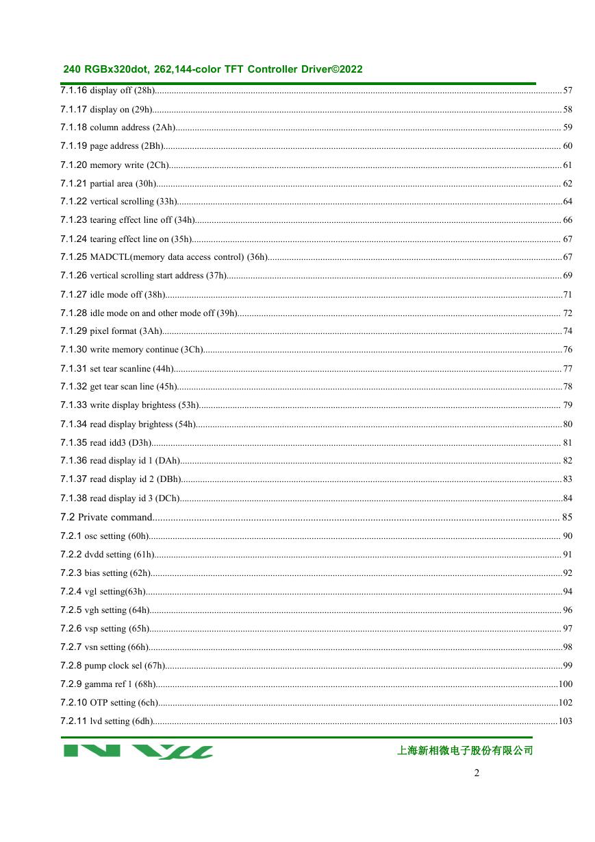
240 RGBx320dot, 262,144-color TFT Controller Driver©2022 7.1.16 display off (28h)..........................................................................................................................................................................57 7.1.17 display on (29h)...........................................................................................................................................................................58 7.1.18 column address (2Ah)................................................................................................................................................................. 59 7.1.19 page address (2Bh)...................................................................................................................................................................... 60 7.1.20 memory write (2Ch)....................................................................................................................................................................61 7.1.21 partial area (30h)......................................................................................................................................................................... 62 7.1.22 vertical scrolling (33h).................................................................................................................................................................64 7.1.23 tearing effect line off (34h)......................................................................................................................................................... 66 7.1.24 tearing effect line on (35h).......................................................................................................................................................... 67 7.1.25 MADCTL(memory data access control) (36h)...........................................................................................................................67 7.1.26 vertical scrolling start address (37h)............................................................................................................................................69 7.1.27 idle mode off (38h)......................................................................................................................................................................71 7.1.28 idle mode on and other mode off (39h)....................................................................................................................................... 72 7.1.29 pixel format (3Ah).......................................................................................................................................................................74 7.1.30 write memory continue (3Ch)......................................................................................................................................................76 7.1.31 set tear scanline (44h).................................................................................................................................................................. 77 7.1.32 get tear scan line (45h).................................................................................................................................................................78 7.1.33 write display brightess (53h)....................................................................................................................................................... 79 7.1.34 read display brightess (54h).........................................................................................................................................................80 7.1.35 read idd3 (D3h)........................................................................................................................................................................... 81 7.1.36 read display id 1 (DAh)............................................................................................................................................................... 82 7.1.37 read display id 2 (DBh)...............................................................................................................................................................83 7.1.38 read display id 3 (DCh)................................................................................................................................................................84 7.2 Private command............................................................................................................................................................. 85 7.2.1 osc setting (60h)............................................................................................................................................................................ 90 7.2.2 dvdd setting (61h).......................................................................................................................................................................... 91 7.2.3 bias setting (62h)............................................................................................................................................................................92 7.2.4 vgl setting(63h)..............................................................................................................................................................................94 7.2.5 vgh setting (64h)............................................................................................................................................................................ 96 7.2.6 vsp setting (65h)............................................................................................................................................................................ 97 7.2.7 vsn setting (66h).............................................................................................................................................................................98 7.2.8 pump clock sel (67h)......................................................................................................................................................................99 7.2.9 gamma ref 1 (68h)........................................................................................................................................................................100 7.2.10 OTP setting (6ch).......................................................................................................................................................................102 7.2.11 lvd setting (6dh).........................................................................................................................................................................103 上海新相微电子股份有限公司 2
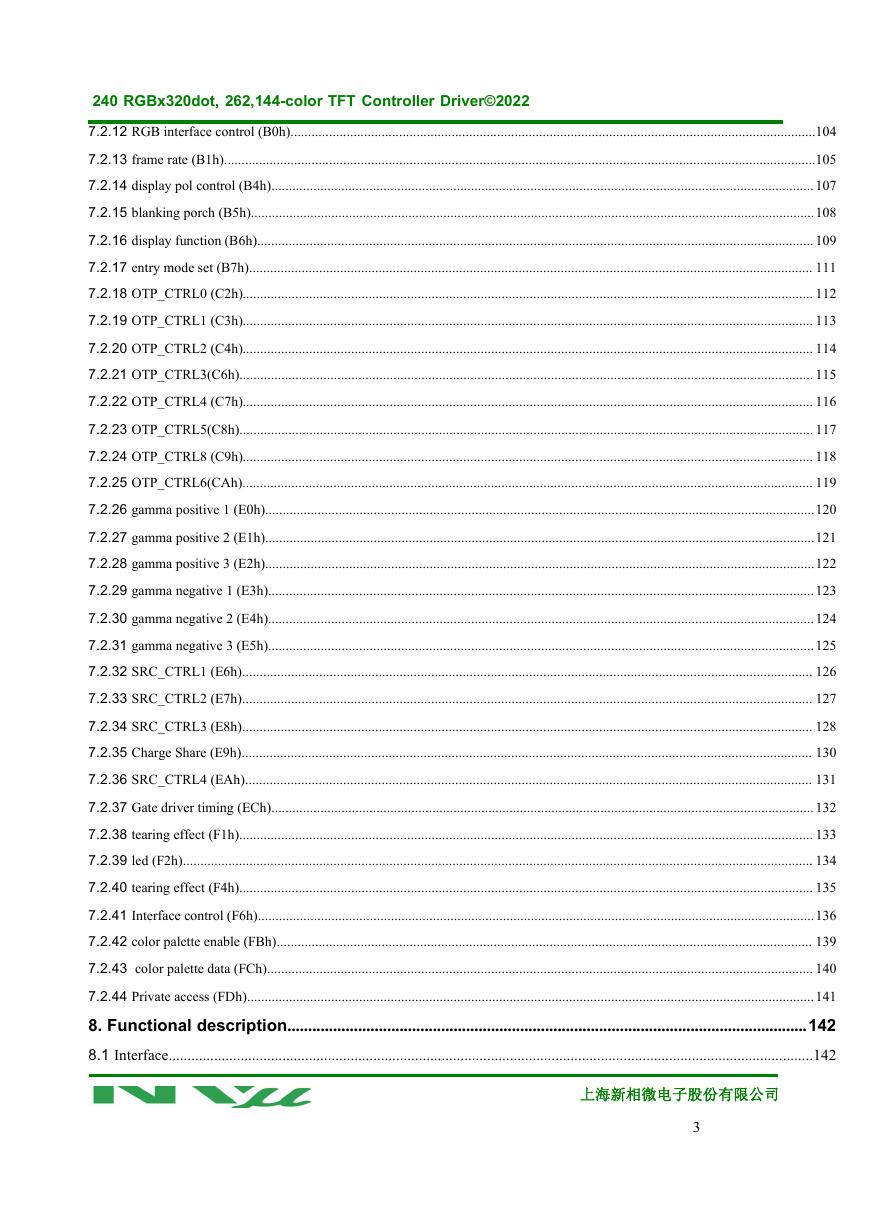
240 RGBx320dot, 262,144-color TFT Controller Driver©2022 7.2.12 RGB interface control (B0h)......................................................................................................................................................104 7.2.13 frame rate (B1h).........................................................................................................................................................................105 7.2.14 display pol control (B4h)...........................................................................................................................................................107 7.2.15 blanking porch (B5h).................................................................................................................................................................108 7.2.16 display function (B6h)............................................................................................................................................................... 109 7.2.17 entry mode set (B7h)................................................................................................................................................................. 111 7.2.18 OTP_CTRL0 (C2h)................................................................................................................................................................... 112 7.2.19 OTP_CTRL1 (C3h)................................................................................................................................................................... 113 7.2.20 OTP_CTRL2 (C4h)................................................................................................................................................................... 114 7.2.21 OTP_CTRL3(C6h).................................................................................................................................................................... 115 7.2.22 OTP_CTRL4 (C7h)................................................................................................................................................................... 116 7.2.23 OTP_CTRL5(C8h).................................................................................................................................................................... 117 7.2.24 OTP_CTRL8 (C9h)................................................................................................................................................................... 118 7.2.25 OTP_CTRL6(CAh)................................................................................................................................................................... 119 7.2.26 gamma positive 1 (E0h).............................................................................................................................................................120 7.2.27 gamma positive 2 (E1h).............................................................................................................................................................121 7.2.28 gamma positive 3 (E2h).............................................................................................................................................................122 7.2.29 gamma negative 1 (E3h)............................................................................................................................................................123 7.2.30 gamma negative 2 (E4h)............................................................................................................................................................124 7.2.31 gamma negative 3 (E5h)............................................................................................................................................................125 7.2.32 SRC_CTRL1 (E6h)................................................................................................................................................................... 126 7.2.33 SRC_CTRL2 (E7h)................................................................................................................................................................... 127 7.2.34 SRC_CTRL3 (E8h)................................................................................................................................................................... 128 7.2.35 Charge Share (E9h)................................................................................................................................................................... 130 7.2.36 SRC_CTRL4 (EAh).................................................................................................................................................................. 131 7.2.37 Gate driver timing (ECh)...........................................................................................................................................................132 7.2.38 tearing effect (F1h).................................................................................................................................................................... 133 7.2.39 led (F2h).................................................................................................................................................................................... 134 7.2.40 tearing effect (F4h).................................................................................................................................................................... 135 7.2.41 Interface control (F6h)...............................................................................................................................................................136 7.2.42 color palette enable (FBh)......................................................................................................................................................... 139 7.2.43 color palette data (FCh)............................................................................................................................................................ 140 7.2.44 Private access (FDh)..................................................................................................................................................................141 8. Functional description.............................................................................................................................142 8.1 Interface..........................................................................................................................................................................142 上海新相微电子股份有限公司 3
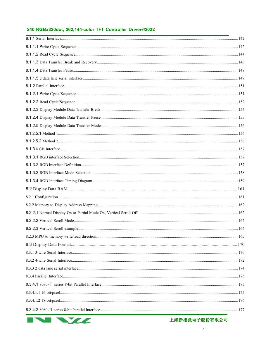
240 RGBx320dot, 262,144-color TFT Controller Driver©2022 8.1.1 Serial Interface.............................................................................................................................................................................142 8.1.1.1 Write Cycle Sequence..............................................................................................................................................................142 8.1.1.2 Read Cycle Sequence...............................................................................................................................................................144 8.1.1.3 Data Transfer Break and Recovery..........................................................................................................................................146 8.1.1.4 Data Transfer Pause................................................................................................................................................................. 148 8.1.1.5 2 data lane serial interface........................................................................................................................................................149 8.1.2 Parallel Interface..........................................................................................................................................................................151 8.1.2.1 Write Cycle/Sequence..............................................................................................................................................................151 8.1.2.2 Read Cycle/Sequence...............................................................................................................................................................152 8.1.2.3 Display Module Data Transfer Break...................................................................................................................................... 154 8.1.2.4 Display Module Data Transfer Pause...................................................................................................................................... 155 8.1.2.5 Display Module Data Transfer Modes.....................................................................................................................................156 8.1.2.5.1 Method 1................................................................................................................................................................................156 8.1.2.5.2 Method 2................................................................................................................................................................................156 8.1.3 RGB Interface..............................................................................................................................................................................157 8.1.3.1 RGB interface Selection........................................................................................................................................................... 157 8.1.3.2 RGB Interface Definition......................................................................................................................................................... 157 8.1.3.3 RGB Interface Mode Selection................................................................................................................................................158 8.1.3.4 RGB Interface Timing Diagram.............................................................................................................................................. 159 8.2 Display Data RAM.........................................................................................................................................................161 8.2.1 Configuration................................................................................................................................................................................161 8.2.2 Memory to Display Address Mapping......................................................................................................................................... 162 8.2.2.1 Normal Display On or Partial Mode On, Vertical Scroll Off..................................................................................................162 8.2.2.2 Vertical Scroll Mode................................................................................................................................................................ 162 8.2.2.3 Vertical Scroll example............................................................................................................................................................164 8.2.3 MPU to memory write/read direction.......................................................................................................................................... 165 8.3 Display Data Format......................................................................................................................................................170 8.3.1 3-wire Serial Interface.................................................................................................................................................................. 170 8.3.2 4-wire Serial Interface.................................................................................................................................................................. 172 8.3.3 2 data lane serial interface............................................................................................................................................................174 8.3.4 Parallel Interface...........................................................................................................................................................................175 8.3.4.1 8080-Ⅰ series 8-bit Parallel Interface..................................................................................................................................... 175 8.3.4.1.1 16-bit/pixel..............................................................................................................................................................................175 8.3.4.1.2 18-bit/pixel..............................................................................................................................................................................176 8.3.4.2 8080-Ⅱ series 8-bit Parallel Interface.......................................................................................................................................177 上海新相微电子股份有限公司 4
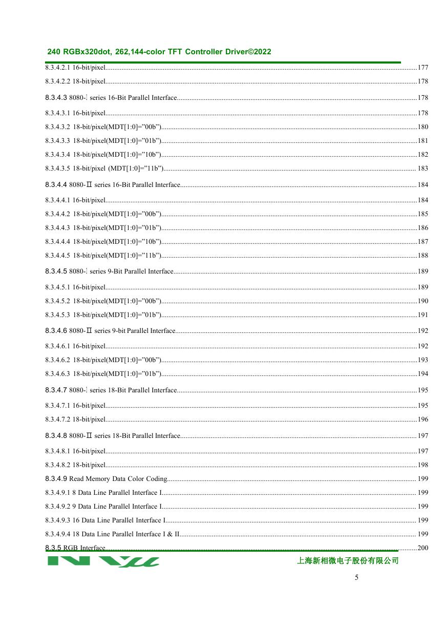
240 RGBx320dot, 262,144-color TFT Controller Driver©2022 8.3.4.2.1 16-bit/pixel..............................................................................................................................................................................177 8.3.4.2.2 18-bit/pixel..............................................................................................................................................................................178 8.3.4.3 8080-Ⅰ series 16-Bit Parallel Interface......................................................................................................................................178 8.3.4.3.1 16-bit/pixel..............................................................................................................................................................................178 8.3.4.3.2 18-bit/pixel(MDT[1:0]=”00b”)...............................................................................................................................................180 8.3.4.3.3 18-bit/pixel(MDT[1:0]=”01b”)...............................................................................................................................................181 8.3.4.3.4 18-bit/pixel(MDT[1:0]=”10b”)...............................................................................................................................................182 8.3.4.3.5 18-bit/pixel (MDT[1:0]=”11b”)............................................................................................................................................. 183 8.3.4.4 8080-Ⅱ series 16-Bit Parallel Interface....................................................................................................................................184 8.3.4.4.1 16-bit/pixel..............................................................................................................................................................................184 8.3.4.4.2 18-bit/pixel(MDT[1:0]=”00b”)...............................................................................................................................................185 8.3.4.4.3 18-bit/pixel(MDT[1:0]=”01b”)...............................................................................................................................................186 8.3.4.4.4 18-bit/pixel(MDT[1:0]=”10b”)...............................................................................................................................................187 8.3.4.4.5 18-bit/pixel(MDT[1:0]=”11b”)...............................................................................................................................................188 8.3.4.5 8080-Ⅰ series 9-Bit Parallel Interface........................................................................................................................................189 8.3.4.5.1 16-bit/pixel..............................................................................................................................................................................189 8.3.4.5.2 18-bit/pixel(MDT[1:0]=”00b”)...............................................................................................................................................190 8.3.4.5.3 18-bit/pixel(MDT[1:0]=”01b”)...............................................................................................................................................191 8.3.4.6 8080-Ⅱ series 9-bit Parallel Interface.......................................................................................................................................192 8.3.4.6.1 16-bit/pixel..............................................................................................................................................................................192 8.3.4.6.2 18-bit/pixel(MDT[1:0]=”00b”)...............................................................................................................................................193 8.3.4.6.3 18-bit/pixel(MDT[1:0]=”01b”)...............................................................................................................................................194 8.3.4.7 8080-Ⅰ series 18-Bit Parallel Interface......................................................................................................................................195 8.3.4.7.1 16-bit/pixel..............................................................................................................................................................................195 8.3.4.7.2 18-bit/pixel..............................................................................................................................................................................196 8.3.4.8 8080-Ⅱ series 18-Bit Parallel Interface....................................................................................................................................197 8.3.4.8.1 16-bit/pixel..............................................................................................................................................................................197 8.3.4.8.2 18-bit/pixel..............................................................................................................................................................................198 8.3.4.9 Read Memory Data Color Coding........................................................................................................................................... 199 8.3.4.9.1 8 Data Line Parallel Interface I.............................................................................................................................................. 199 8.3.4.9.2 9 Data Line Parallel Interface I.............................................................................................................................................. 199 8.3.4.9.3 16 Data Line Parallel Interface I............................................................................................................................................ 199 8.3.4.9.4 18 Data Line Parallel Interface I & II.................................................................................................................................... 199 8.3.5 RGB Interface..............................................................................................................................................................................200 上海新相微电子股份有限公司 5
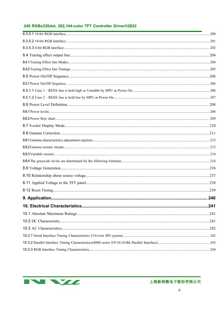
240 RGBx320dot, 262,144-color TFT Controller Driver©2022 8.3.5.1 16-bit RGB interface................................................................................................................................................................200 8.3.5.2 18-bit RGB interface................................................................................................................................................................201 8.3.5.3 6-bit RGB interface..................................................................................................................................................................202 8.4 Tearing effect output line.............................................................................................................................................. 204 8.4.1Tearing Effect line Modes............................................................................................................................................................. 204 8.4.2Tearing Effect line Timings...........................................................................................................................................................205 8.5 Power On/Off Sequence................................................................................................................................................206 8.5.1Power On/Off Sequence................................................................................................................................................................206 8.5.1.1 Case 1 – RESX line is held high or Unstable by MPU at Power On...................................................................................... 206 8.5.1.2 Case 2 – RESX line is held low by MPU at Power On...........................................................................................................207 8.6 Power Level Definition................................................................................................................................................. 208 8.6.1Power levels.................................................................................................................................................................................. 208 8.6.2Power flow chart........................................................................................................................................................................... 209 8.7 8-color Display Mode....................................................................................................................................................210 8.8 Gamma Correction.........................................................................................................................................................211 8.8.1Gamma-characteristics adjustment registers..................................................................................................................................212 8.8.2Gamma resister stream..................................................................................................................................................................213 8.8.3Variable resister.............................................................................................................................................................................214 8.8.4The grayscale levels are determined by the following formulas..................................................................................................216 8.9 Voltage Generation........................................................................................................................................................236 8.10 Relationship about source voltage.............................................................................................................................. 237 8.11 Applied Voltage to the TFT panel.............................................................................................................................. 238 8.12 Reset Timing................................................................................................................................................................239 9. Application.................................................................................................................................................. 240 10. Electrical Characteristics......................................................................................................................241 10.1 Absolute Maximum Ratings........................................................................................................................................241 10.2 DC Characteristic.........................................................................................................................................................241 10.3 AC Characteristics.......................................................................................................................................................242 10.3.1 Serial Interface Timing Characteristics (3/4-wire SPI system)................................................................................................ 242 10.3.2 Parallel Interface Timing Characteristics(8080 series 8/9/16/18-Bit Parallel Interface)..........................................................243 10.3.3 RGB Interface Timing Characteristics......................................................................................................................................244 上海新相微电子股份有限公司 6
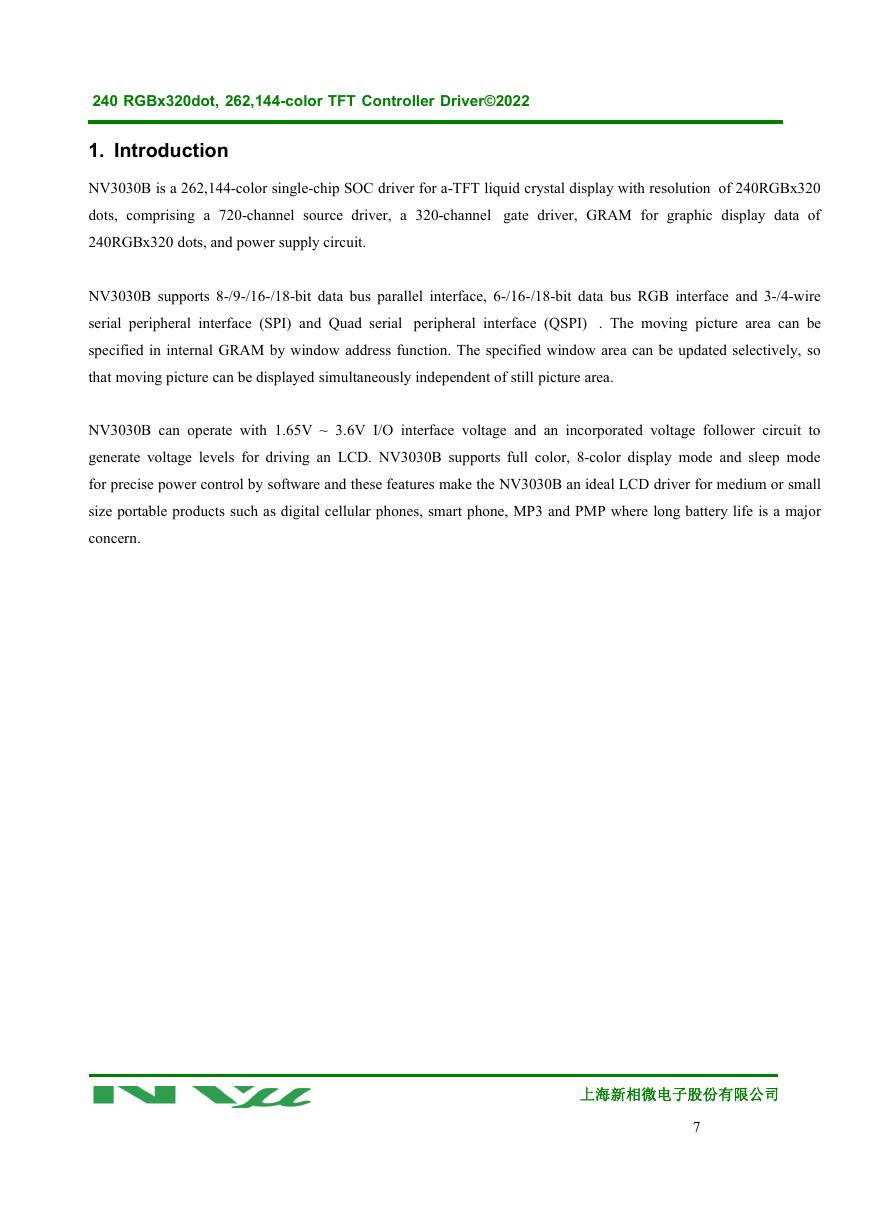
240 RGBx320dot, 262,144-color TFT Controller Driver©2022 1. Introduction NV3030B is a 262,144-color single-chip SOC driver for a-TFT liquid crystal display with resolution of 240RGBx320 dots, comprising a 720-channel source driver, a 320-channel gate driver, GRAM for graphic display data of 240RGBx320 dots, and power supply circuit. NV3030B supports 8-/9-/16-/18-bit data bus parallel interface, 6-/16-/18-bit data bus RGB interface and 3-/4-wire serial peripheral interface (SPI) and Quad serial peripheral interface (QSPI) . The moving picture area can be specified in internal GRAM by window address function. The specified window area can be updated selectively, so that moving picture can be displayed simultaneously independent of still picture area. NV3030B can operate with 1.65V ~ 3.6V I/O interface voltage and an incorporated voltage follower circuit to generate voltage levels for driving an LCD. NV3030B supports full color, 8-color display mode and sleep mode for precise power control by software and these features make the NV3030B an ideal LCD driver for medium or small size portable products such as digital cellular phones, smart phone, MP3 and PMP where long battery life is a major concern. 上海新相微电子股份有限公司 7
分享到:
收藏