SX1303
LoRa Gateway Baseband Processor
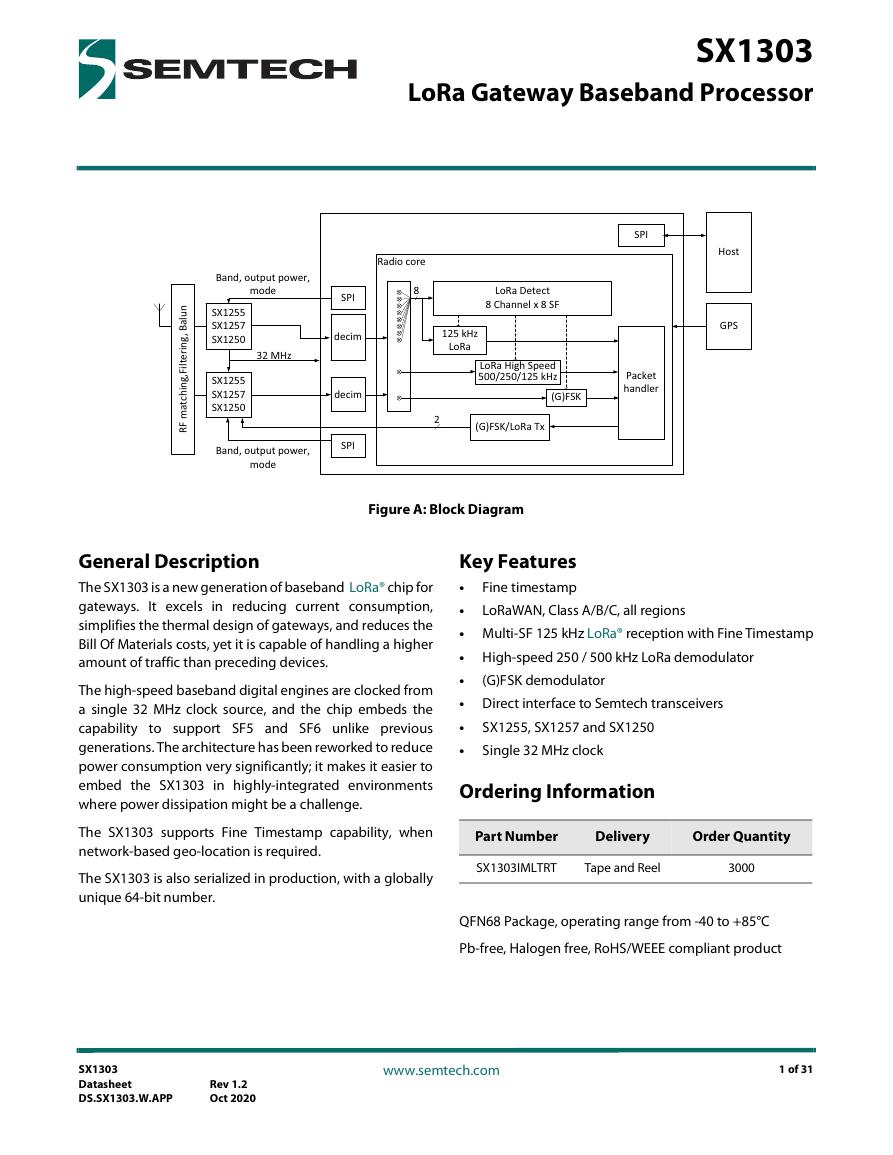
Figure A: Block Diagram
General Description
The SX1303 is a new generation of baseband LoRa® chip for
gateways. It excels in reducing current consumption,
simplifies the thermal design of gateways, and reduces the
Bill Of Materials costs, yet it is capable of handling a higher
amount of traffic than preceding devices.
The high-speed baseband digital engines are clocked from
a single 32 MHz clock source, and the chip embeds the
capability to support SF5 and SF6 unlike previous
generations. The architecture has been reworked to reduce
power consumption very significantly; it makes it easier to
embed the SX1303 in highly-integrated environments
where power dissipation might be a challenge.
The SX1303 supports Fine Timestamp capability, when
network-based geo-location is required.
The SX1303 is also serialized in production, with a globally
unique 64-bit number.
Key Features
•
Fine timestamp
•
LoRaWAN, Class A/B/C, all regions
• Multi-SF 125 kHz LoRa® reception with Fine Timestamp
• High-speed 250 / 500 kHz LoRa demodulator
•
• Direct interface to Semtech transceivers
•
•
SX1255, SX1257 and SX1250
Single 32 MHz clock
(G)FSK demodulator
Ordering Information
Part Number
Delivery
Order Quantity
SX1303IMLTRT
Tape and Reel
3000
QFN68 Package, operating range from -40 to +85°C
Pb-free, Halogen free, RoHS/WEEE compliant product
SX1303
Datasheet
DS.SX1303.W.APP
Rev 1.2
Oct 2020
www.semtech.com
1 of 31
�
Revision History
Version
ECO
Date
Modifications
Rev 1.0
Rev 1.1
Rev 1.2
ECO-051672
April 2020
First Release
ECO-053422
September 2020
Edit the link to the HAL/Packet Forwarder repository
ECO-053763
October 2020
Update title to “LoRa Gateway Baseband Processor”
SX1303
Datasheet
DS.SX1303.W.APP
Rev 1.2
Oct 2020
www.semtech.com
2 of 31
�
Table of Contents
General Description.............................................................................................................................................1
Key Features...........................................................................................................................................................1
Ordering Information .........................................................................................................................................1
Revision History ....................................................................................................................................................2
List of Figures ........................................................................................................................................................5
List of Tables .........................................................................................................................................................6
1. Introduction.......................................................................................................................................................7
1.1 RF Front End Interface ......................................................................................................................7
1.2 Power Distribution .............................................................................................................................7
1.3 Clocking .................................................................................................................................................7
1.4 Detection Engine, Modems and Timestamping .....................................................................7
1.5 Digital Interface and Control ..........................................................................................................7
1.6 Application Programming Interface ............................................................................................7
1.7 Application Information ...................................................................................................................7
2. Pin Connections ...............................................................................................................................................8
2.1 Pinout .....................................................................................................................................................8
2.2 Package View .................................................................................................................................... 11
3. Specifications ................................................................................................................................................. 12
3.1 ESD Notice .......................................................................................................................................... 12
3.2 Absolute Minimum and Maximum Ratings ........................................................................... 13
3.3 Operating Range .............................................................................................................................. 13
3.4 Electrical Specifications ................................................................................................................. 13
3.5 Digital I/O Specifications ............................................................................................................... 14
3.6 Example Reference Design Performance ............................................................................... 14
4. RF Front End Interface................................................................................................................................. 16
5. Power Distribution ....................................................................................................................................... 18
6. Clocking ........................................................................................................................................................... 19
7. Detection Engine - Modems..................................................................................................................... 20
8. Digital Interface and Control .................................................................................................................... 21
8.1 Host SPI Interface ............................................................................................................................. 21
8.1.1 HOST SPI Timings ................................................................................................................ 21
8.1.2 SPI Timings............................................................................................................................. 22
9. Application Programming Interface...................................................................................................... 23
9.1 Globally Unique EUI ........................................................................................................................ 23
10. Application Information .......................................................................................................................... 24
10.1 Geographical Designs ................................................................................................................. 24
10.2 Reference Block Diagram ........................................................................................................... 24
10.3 Reference Design Layout ........................................................................................................... 25
11. Packaging Information............................................................................................................................. 26
11.1 Package Outline Drawing .......................................................................................................... 26
11.2 Package Marking ........................................................................................................................... 27
11.3 Land Pattern ................................................................................................................................... 27
11.4 Reflow Profiles ................................................................................................................................ 28
SX1303
Datasheet
DS.SX1303.W.APP
Rev 1.2
Oct 2020
www.semtech.com
3 of 31
�
11.5 Tape and Reel Specification ...................................................................................................... 28
11.6 Thermal Impedance ..................................................................................................................... 28
Glossary ................................................................................................................................................................ 29
SX1303
Datasheet
DS.SX1303.W.APP
Rev 1.2
Oct 2020
www.semtech.com
4 of 31
�
List of Figures
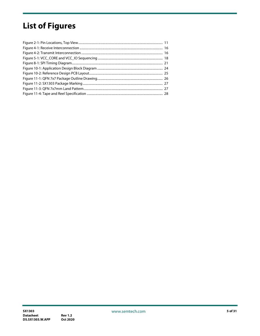
Figure 2-1: Pin Locations, Top View........................................................................................................... 11
Figure 4-1: Receive Interconnection ......................................................................................................... 16
Figure 4-2: Transmit Interconnection ....................................................................................................... 16
Figure 5-1: VCC_CORE and VCC_IO Sequencing .................................................................................. 18
Figure 8-1: SPI Timing Diagram................................................................................................................... 21
Figure 10-1: Application Design Block Diagram ................................................................................... 24
Figure 10-2: Reference Design PCB Layout............................................................................................. 25
Figure 11-1: QFN 7x7 Package Outline Drawing................................................................................... 26
Figure 11-2: SX1303 Package Marking ..................................................................................................... 27
Figure 11-3: QFN 7x7mm Land Pattern.................................................................................................... 27
Figure 11-4: Tape and Reel Specification ................................................................................................ 28
SX1303
Datasheet
DS.SX1303.W.APP
Rev 1.2
Oct 2020
www.semtech.com
5 of 31
�
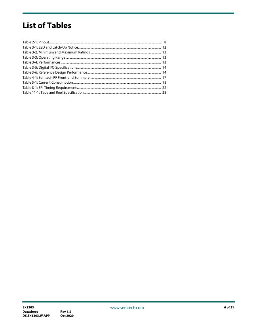
List of Tables
Table 2-1: Pinout.................................................................................................................................................. 8
Table 3-1: ESD and Latch-Up Notice.......................................................................................................... 12
Table 3-2: Minimum and Maximum Ratings .......................................................................................... 13
Table 3-3: Operating Range.......................................................................................................................... 13
Table 3-4: Performances ................................................................................................................................ 13
Table 3-5: Digital I/O Specifications........................................................................................................... 14
Table 3-6: Reference Design Performance.............................................................................................. 14
Table 4-1: Semtech RF Front-end Summary........................................................................................... 17
Table 5-1: Current Consumption ................................................................................................................ 18
Table 8-1: SPI Timing Requirements.......................................................................................................... 22
Table 11-1: Tape and Reel Specification .................................................................................................. 28
SX1303
Datasheet
DS.SX1303.W.APP
Rev 1.2
Oct 2020
www.semtech.com
6 of 31
�
1. Introduction
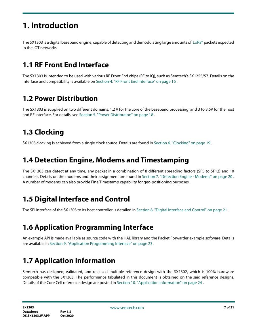
The SX1303 is a digital baseband engine, capable of detecting and demodulating large amounts of LoRa® packets expected
in the IOT networks.
1.1 RF Front End Interface
The SX1303 is intended to be used with various RF Front End chips (RF to IQ), such as Semtech’s SX1255/57. Details on the
interface and compatibility is available on Section 4. "RF Front End Interface" on page 16 .
1.2 Power Distribution
The SX1303 is supplied on two different domains, 1.2 V for the core of the baseband processing, and 3 to 3.6V for the host
and RF interface. For details, see Section 5. "Power Distribution" on page 18 .
1.3 Clocking
SX1303 clocking is achieved from a single clock source. Details are found in Section 6. "Clocking" on page 19 .
1.4 Detection Engine, Modems and Timestamping
The SX1303 can detect at any time, any packet in a combination of 8 different spreading factors (SF5 to SF12) and 10
channels. Details on the modems and their assignment are found in Section 7. "Detection Engine - Modems" on page 20 .
A number of modems can also provide Fine Timestamp capability for geo-positioning purposes.
1.5 Digital Interface and Control
The SPI interface of the SX1303 to its host controller is detailed in Section 8. "Digital Interface and Control" on page 21 .
1.6 Application Programming Interface
An example API is made available as source code with the HAL library and the Packet Forwarder example software. Details
are available in Section 9. "Application Programming Interface" on page 23 .
1.7 Application Information
Semtech has designed, validated, and released multiple reference design with the SX1302, which is 100% hardware
compatible with the SX1303. The performance tabulated in this document is obtained on the said reference designs.
Details of the Core Cell reference design are posted in Section 10. "Application Information" on page 24 .
SX1303
Datasheet
DS.SX1303.W.APP
Rev 1.2
Oct 2020
www.semtech.com
7 of 31
�
2. Pin Connections
2.1 Pinout
Table 2-1: Pinout
Pin
Number
Pin Name
Direction
Description
SX1250
SX1255/57
(0)
GND
HOST_CSN
Power
Input
Ground
External HOST SPI CSN pin
HOST_MISO
Output
External HOST SPI MISO pin
HOST_MOSI
HOST_SCK
VCC_CORE
GND
RESET
PPS
GND
Input
Input
Power
Power
Input
Input
Power
External HOST SPI MOSI pin
External HOST SPI SCK pin
Core supply
Ground
Asynchronous Reset Input
PPS input from GPS
Ground
RADIO_CTRL[0]
Output
Radio A Enable LDO
RADIO_CTRL[1]
Output
Radio A Enable LNA and control switch
RADIO_CTRL[2]
Output
Radio A Enable PA and control switch
RADIO_CTRL[3]
Output
Radio A Reset
NRESET
RESET
VCC_IO
GND
Power
Power
IO supply
Ground
RADIO_CTRL[4]
Output
Radio A PA gain_0
RADIO_CTRL[5]
Output
Radio A PA gain_1
RADIO_B_CSN
Output
Radio B SPI CSN pin
RADIO_B_MOSI
Output
Radio B SPI MOSI pin
SP_VALID
Input
Stream synchronization for FPGA
RADIO_B_SCK
Output
Radio B SPI SCK pin
RADIO_CTRL[6]
Output
Radio B Enable LDO
VCC_CORE
Power
Core supply
NSS
MOSI
SCK
NSS
MOSI
SCK
1
2
3
4
5
6
7
8
9
10
11
12
13
14
15
16
17
18
19
20
21
22
23
SX1303
Datasheet
DS.SX1303.W.APP
Rev 1.2
Oct 2020
www.semtech.com
8 of 31
�


 V2版本原理图(Capacitive-Fingerprint-Reader-Schematic_V2).pdf
 摄像头工作原理.doc
 VL53L0X简要说明(En.FLVL53L00216).pdf
 原理图(DVK720-Schematic).pdf
 原理图(Pico-Clock-Green-Schdoc).pdf
 原理图(RS485-CAN-HAT-B-schematic).pdf
 File:SIM7500_SIM7600_SIM7800 Series_SSL_Application Note_V2.00.pdf
 ADS1263(Ads1262).pdf
 原理图(Open429Z-D-Schematic).pdf
 用户手册(Capacitive_Fingerprint_Reader_User_Manual_CN).pdf
 CY7C68013A(英文版)(CY7C68013A).pdf
 TechnicalReference_Dem.pdf