logo资料库

RA8875_Specification(RA8875_Specification).pdf

第1页 / 共174页
第2页 / 共174页
第3页 / 共174页
第4页 / 共174页
第5页 / 共174页
第6页 / 共174页
第7页 / 共174页
第8页 / 共174页
资料共174页,剩余部分请下载后查看
1. Description
2. Features
3. Block Diagram
3-1 Block Diagram
3-2 System Block Diagram
4. Pin Description
4-1 MCU Interface
4-2 Serial MCU Interface
4-3 LCD Panel Interface
4-4 Serial Flash/ROM Interface
4-5 Touch Interface
4-6 KEYSCAN Interface
4-7 PWM Interface
4-8 Clock and Power Interface
5. Register
5-1 Status Register
5-2 System & Configuration Registers
5-3 LCD Display Control Registers
5-4 Active Window & Scroll Window Setting Registers
5-5 Cursor Setting Registers
5-6 Block Transfer Engine(BTE) Control Registers
5-7 Touch Panel Control Registers
5-8 Graphic Cursor Setting Registers
5-9 PLL Setting Registers
5-10 PWM Control Registers
5-11 Drawing Control Registers
5-12 Drawing Control Registers
5-13 Key & IO Control Registers
5-14 Floating Window Control Registers
5-15 Serial Flash Control Registers
5-16 Interrupt Control Registers
6. Hardware Interface
6-1 MCU Interface
6-1-1 Protocol
6-1-1-1 Parallel I/F Protocol
6-1-2 Serial I/F Protocol
6-1-2-1 3-Wire SPI Interface
6-1-2-2 4-Wire SPI Interface
6-1-2-3 IIC I/F
6-1-3 Read Status Register
6-1-4 Write Command to Register
6-1-5 Memory Read / Write Operation
6-1-6 Interrupt and Wait
6-1-6-1 Interrupt
6-1-6-2 Wait
6-1-7 Data Format
6-1-7-1 MCU Data Bus 16- Bit
6-1-7-2 MCU Data Bus 8-Bit
6-2 Driver I/F Color Setting Mode
6-3 LCD Interface
6-3-1 Digital TFT Interface
6-4 External Serial Flash/ROM
6-4-1 External Serial Font ROM
6-4-2 External Serial Data ROM
6-5 Touch Panel I/F
6-6 KEYSCAN
6-7 PWM
6-8 Clock and PLL
6-9 Reset
6-10 Power
6-10-1 Power Pin Description
6-10-2 Power Architecture
7. Function Description
7-1 Scroll Function
7-1-1 Scroll Window & Scroll Offset
7-1-2 Horizontal Scroll & Vertical Scroll
7-1-3 Layer Mixed Scroll
7-1-3-1 Layer 1/2 Scroll Simultaneously
7-1-3-2 Only Layer 1 Scroll
7-1-3-3 Only Layer 2 Scroll
7-1-3-4 Buffer Scroll (Layer 2 is used as Scroll Buffer)
7-2 Active Window
7-2-1 Active Window for Font Write
7-2-2 Active Window for Geometric Input
7-2-3 Active Window for DMA
7-2-4 Active Window for Memory Write
7-3 Cursor & Pattern
7-3-1 Cursor Type
7-3-1-1 Graphic Cursor
7-3-1-2 Memory Read Cursor
7-3-1-3 Memory Write Cursor
7-3-1-4 Font Write Cursor
7-3-2 Cursor Attribute
7-3-2-1 Cursor Blinking
7-3-2-2 Cursor Height and Width
7-3-3 Pattern
7-4 Font
7-4-1 Internal Font ROM
7-4-2 External Font ROM
7-4-3 CGRAM
7-4-4 90 Degree Font
7-4-5 Enlargement, Transparent Font
7-4-6 Font Change Line when Setting Write Auto Move
7-4-7 Font Full-Alignment
7-5 Geometric Pattern Drawing Engine
7-5-1 Circle Input
7-5-2 Ellipse Input
7-5-3 Curve Input
7-5-4 Square Input
7-5-5 Line Input
7-5-6 Triangle Input
7-5-7 Square Of Circlar Corner Input
7-6 BTE (Block Transfer Engine) Function
7-6-1 Select BTE Start Point Address and Layer
7-6-2 BTE Operations
7-6-2-1 Write BTE
7-6-2-2 Read BTE
7-6-2-3 Move BTE
7-6-2-4 Solid Fill
7-6-2-5 Pattern Fill
7-6-2-6 Transparent Pattern Fill
7-6-2-7 Transparent Write BTE
7-6-2-8 Transparent Move BTE
7-6-2-9 Color Expansion
7-6-2-10 Move BTE with Color Expansion
7-6-3 BTE Access Memory Method
7-6-3-1 Block Memory Access
7-6-3-2 Linear Memory Access
7-6-4 BTE Function Explaination
7-6-4-1 Write BTE with ROP
7-6-4-2 Read BTE (Burst Read Like Function)
7-6-4-3 Move BTE in Positive Direction with ROP
7-6-4-4 Move BTE in Negative Direction with ROP
7-6-4-5 Transparent Write BTE
7-6-4-6 Transparent Move BTE Positive Direction
7-6-4-7 Pattern Fill with ROP
7-6-4-8 Pattern Fill with Transparency
7-6-4-9 Color Expansion
7-6-4-10 Color Expansion with Transparency
7-6-4-11 Move BTE with Color Expansion
7-6-4-12 Move BTE with Color Expansion and Transparency
7-6-4-13 Solid Fill
7-7 Layer Mixed Function
7-7-1 Only Layer One is Visible
7-7-2 Only Layer Two is Visible
7-7-3 Lighten-Overlay Mode
7-7-4 Transparent Mode
7-7-5 Boolean OR
7-7-6 Boolean AND
7-7-7 Floating Window
7-8 Touch Panel Function
7-8-1 Touch Panel Operation Mode
7-8-1-1 Auto Mode
7-8-1-2 Manual Mode
7-8-2 Touch Event Detection Modes
7-8-2-1 External Interrupt Mode
7-8-2-2 Software Polling Mode
7-8-3 Touch Panel Sampling Time Reference Table
7-9 KEYSCAN
7-10 DMA(Direct Memory Access)
7-10-1 DMA In Contineous Mode
7-10-2 DMA In Block Mode
7-11 PWM
7-12 Sleep Mode
8. AC/DC Characteristic
8-1 Maximum Absolute Limit
8-2 DC Characteristic
9. Package
9-1 Pin Assignment
9-2 Package Outline Dimensions
9-3 Product Number
RAiO RA8875 Character/Graphic TFT LCD Controller Specification Draft Version 0.1 January 26, 2011 RAiO Technology Inc. ©Copyright RAiO Technology Inc. 2011 RAiO TECHNOLOGY INC. 1/174 www.raio.com.tw
Draft Version 0.1 Character / Graphic TFT LCD Controller RA8875 Version Date Description 0.1 January 26, 2011 Draft Version Update History RAiO TECHNOLOGY INC. 2/174 www.raio.com.tw
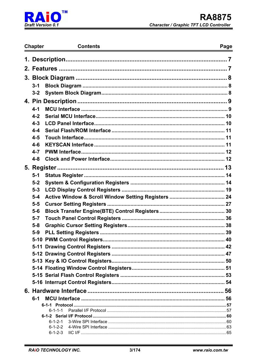
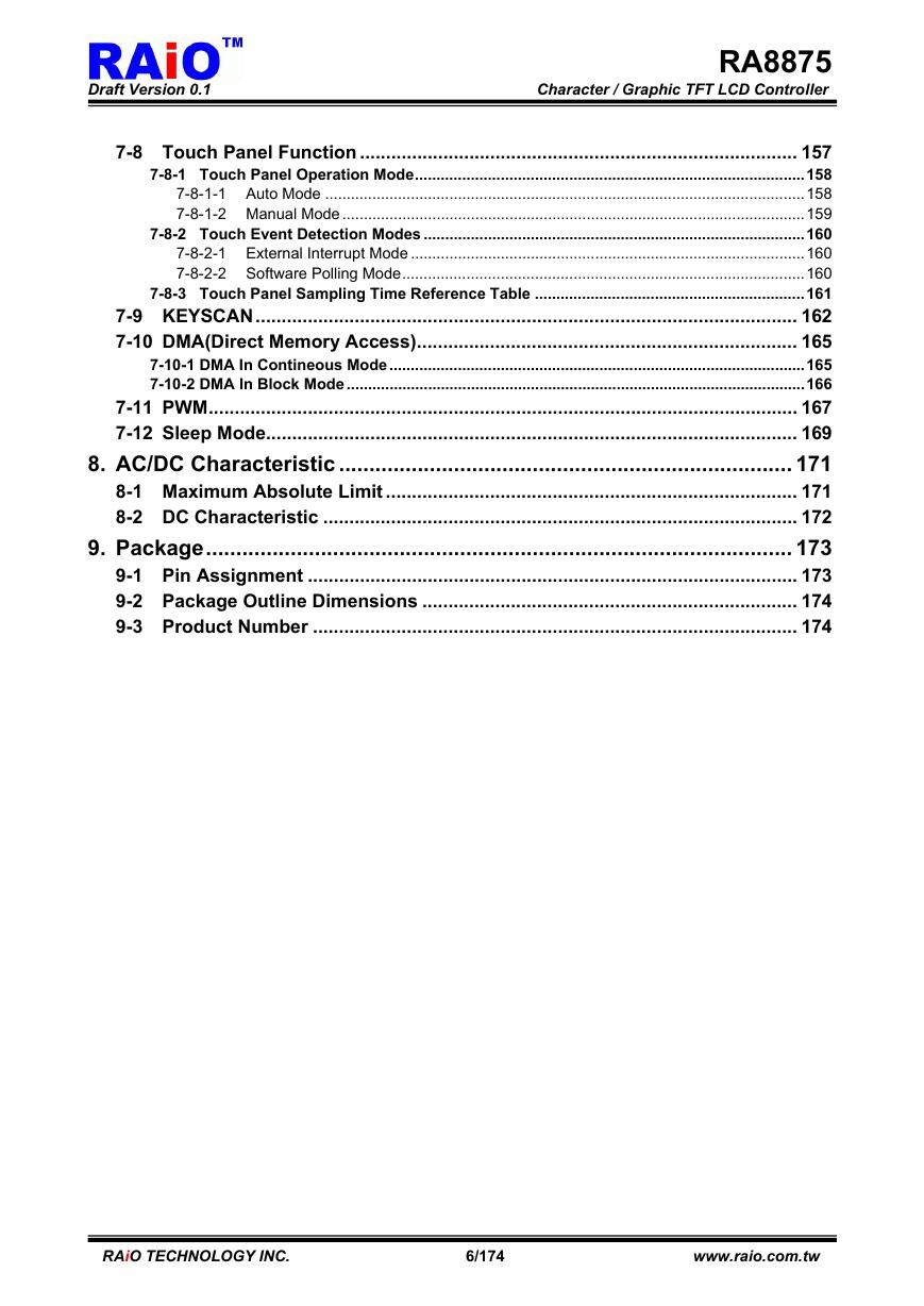
Draft Version 0.1 Character / Graphic TFT LCD Controller RA8875 Page Contents Chapter 1. Description................................................................................................ 7 2. Features .................................................................................................... 7 3. Block Diagram .......................................................................................... 8 3-1 Block Diagram .................................................................................................... 8 3-2 System Block Diagram....................................................................................... 8 4. Pin Description ......................................................................................... 9 4-1 MCU Interface ..................................................................................................... 9 4-2 Serial MCU Interface......................................................................................... 10 4-3 LCD Panel Interface.......................................................................................... 10 4-4 Serial Flash/ROM Interface .............................................................................. 11 4-5 Touch Interface................................................................................................. 11 4-6 KEYSCAN Interface .......................................................................................... 11 4-7 PWM Interface................................................................................................... 12 4-8 Clock and Power Interface............................................................................... 12 5. Register................................................................................................... 13 5-1 Status Register ................................................................................................. 14 5-2 System & Configuration Registers ................................................................. 14 5-3 LCD Display Control Registers ....................................................................... 19 5-4 Active Window & Scroll Window Setting Registers ...................................... 24 5-5 Cursor Setting Registers ................................................................................. 27 5-6 Block Transfer Engine(BTE) Control Registers............................................. 30 5-7 Touch Panel Control Registers ....................................................................... 36 5-8 Graphic Cursor Setting Registers................................................................... 38 5-9 PLL Setting Registers ...................................................................................... 39 5-10 PWM Control Registers.................................................................................... 40 5-11 Drawing Control Registers .............................................................................. 42 5-12 Drawing Control Registers .............................................................................. 47 5-13 Key & IO Control Registers.............................................................................. 50 5-14 Floating Window Control Registers................................................................ 51 5-15 Serial Flash Control Registers ........................................................................ 53 5-16 Interrupt Control Registers.............................................................................. 54 6. Hardware Interface ................................................................................. 56 6-1 MCU Interface ................................................................................................... 56 6-1-1 Protocol ................................................................................................................................57 6-1-1-1 Parallel I/F Protocol ....................................................................................................57 6-1-2 Serial I/F Protocol ................................................................................................................60 6-1-2-1 3-Wire SPI Interface ...................................................................................................60 6-1-2-2 4-Wire SPI Interface ...................................................................................................63 6-1-2-3 IIC I/F ..........................................................................................................................65 RAiO TECHNOLOGY INC. 3/174 www.raio.com.tw
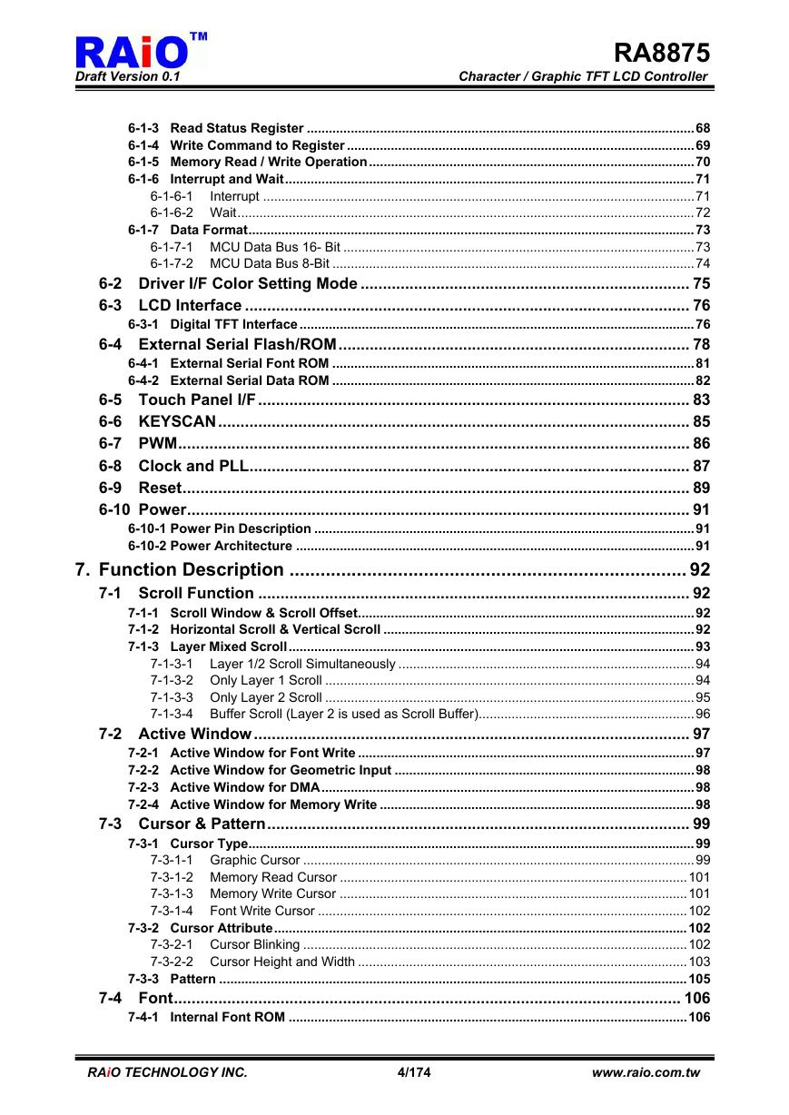
Draft Version 0.1 Character / Graphic TFT LCD Controller RA8875 6-1-3 Read Status Register ..........................................................................................................68 6-1-4 Write Command to Register ...............................................................................................69 6-1-5 Memory Read / Write Operation.........................................................................................70 6-1-6 Interrupt and Wait................................................................................................................71 6-1-6-1 Interrupt ......................................................................................................................71 6-1-6-2 Wait.............................................................................................................................72 6-1-7 Data Format..........................................................................................................................73 6-1-7-1 MCU Data Bus 16- Bit ................................................................................................73 6-1-7-2 MCU Data Bus 8-Bit ...................................................................................................74 6-2 Driver I/F Color Setting Mode .......................................................................... 75 6-3 LCD Interface .................................................................................................... 76 6-3-1 Digital TFT Interface............................................................................................................76 6-4 External Serial Flash/ROM............................................................................... 78 6-4-1 External Serial Font ROM ...................................................................................................81 6-4-2 External Serial Data ROM ...................................................................................................82 6-5 Touch Panel I/F................................................................................................. 83 6-6 KEYSCAN.......................................................................................................... 85 6-7 PWM................................................................................................................... 86 6-8 Clock and PLL................................................................................................... 87 6-9 Reset.................................................................................................................. 89 6-10 Power................................................................................................................. 91 6-10-1 Power Pin Description ........................................................................................................91 6-10-2 Power Architecture .............................................................................................................91 7. Function Description ............................................................................. 92 7-1 Scroll Function ................................................................................................. 92 7-1-1 Scroll Window & Scroll Offset............................................................................................92 7-1-2 Horizontal Scroll & Vertical Scroll .....................................................................................92 7-1-3 Layer Mixed Scroll...............................................................................................................93 7-1-3-1 Layer 1/2 Scroll Simultaneously .................................................................................94 7-1-3-2 Only Layer 1 Scroll .....................................................................................................94 7-1-3-3 Only Layer 2 Scroll .....................................................................................................95 7-1-3-4 Buffer Scroll (Layer 2 is used as Scroll Buffer)...........................................................96 7-2 Active Window.................................................................................................. 97 7-2-1 Active Window for Font Write ............................................................................................97 7-2-2 Active Window for Geometric Input ..................................................................................98 7-2-3 Active Window for DMA......................................................................................................98 7-2-4 Active Window for Memory Write ......................................................................................98 7-3 Cursor & Pattern............................................................................................... 99 7-3-1 Cursor Type..........................................................................................................................99 7-3-1-1 Graphic Cursor ...........................................................................................................99 7-3-1-2 Memory Read Cursor ...............................................................................................101 7-3-1-3 Memory Write Cursor ...............................................................................................101 7-3-1-4 Font Write Cursor .....................................................................................................102 7-3-2 Cursor Attribute.................................................................................................................102 7-3-2-1 Cursor Blinking .........................................................................................................102 7-3-2-2 Cursor Height and Width ..........................................................................................103 7-3-3 Pattern ................................................................................................................................105 7-4 Font.................................................................................................................. 106 7-4-1 Internal Font ROM .............................................................................................................106 RAiO TECHNOLOGY INC. 4/174 www.raio.com.tw
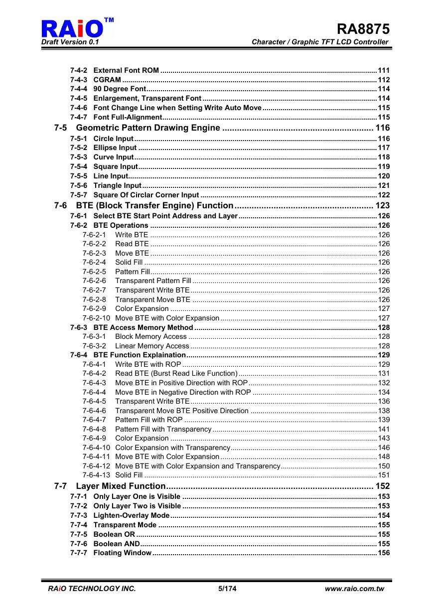
Draft Version 0.1 Character / Graphic TFT LCD Controller RA8875 7-4-2 External Font ROM ............................................................................................................111 7-4-3 CGRAM ...............................................................................................................................112 7-4-4 90 Degree Font...................................................................................................................114 7-4-5 Enlargement, Transparent Font .......................................................................................114 7-4-6 Font Change Line when Setting Write Auto Move.........................................................115 7-4-7 Font Full-Alignment...........................................................................................................115 7-5 Geometric Pattern Drawing Engine .............................................................. 116 7-5-1 Circle Input.........................................................................................................................116 7-5-2 Ellipse Input .......................................................................................................................117 7-5-3 Curve Input.........................................................................................................................118 7-5-4 Square Input.......................................................................................................................119 7-5-5 Line Input............................................................................................................................120 7-5-6 Triangle Input.....................................................................................................................121 7-5-7 Square Of Circlar Corner Input ........................................................................................122 7-6 BTE (Block Transfer Engine) Function......................................................... 123 7-6-1 Select BTE Start Point Address and Layer.....................................................................126 7-6-2 BTE Operations .................................................................................................................126 7-6-2-1 Write BTE .................................................................................................................126 7-6-2-2 Read BTE .................................................................................................................126 7-6-2-3 Move BTE .................................................................................................................126 7-6-2-4 Solid Fill ....................................................................................................................126 7-6-2-5 Pattern Fill.................................................................................................................126 7-6-2-6 Transparent Pattern Fill ............................................................................................126 7-6-2-7 Transparent Write BTE.............................................................................................126 7-6-2-8 Transparent Move BTE ............................................................................................126 7-6-2-9 Color Expansion .......................................................................................................127 7-6-2-10 Move BTE with Color Expansion..............................................................................127 7-6-3 BTE Access Memory Method ...........................................................................................128 7-6-3-1 Block Memory Access ..............................................................................................128 7-6-3-2 Linear Memory Access .............................................................................................128 7-6-4 BTE Function Explaination...............................................................................................129 7-6-4-1 Write BTE with ROP .................................................................................................129 7-6-4-2 Read BTE (Burst Read Like Function) .....................................................................131 7-6-4-3 Move BTE in Positive Direction with ROP................................................................132 7-6-4-4 Move BTE in Negative Direction with ROP ..............................................................134 7-6-4-5 Transparent Write BTE.............................................................................................136 7-6-4-6 Transparent Move BTE Positive Direction ...............................................................138 7-6-4-7 Pattern Fill with ROP ................................................................................................139 7-6-4-8 Pattern Fill with Transparency..................................................................................141 7-6-4-9 Color Expansion .......................................................................................................143 7-6-4-10 Color Expansion with Transparency.........................................................................146 7-6-4-11 Move BTE with Color Expansion..............................................................................148 7-6-4-12 Move BTE with Color Expansion and Transparency................................................150 7-6-4-13 Solid Fill ....................................................................................................................151 7-7 Layer Mixed Function..................................................................................... 152 7-7-1 Only Layer One is Visible .................................................................................................153 7-7-2 Only Layer Two is Visible .................................................................................................153 7-7-3 Lighten-Overlay Mode.......................................................................................................154 7-7-4 Transparent Mode .............................................................................................................155 7-7-5 Boolean OR ........................................................................................................................155 7-7-6 Boolean AND......................................................................................................................155 7-7-7 Floating Window................................................................................................................156 RAiO TECHNOLOGY INC. 5/174 www.raio.com.tw
Draft Version 0.1 Character / Graphic TFT LCD Controller RA8875 7-8 Touch Panel Function .................................................................................... 157 7-8-1 Touch Panel Operation Mode...........................................................................................158 7-8-1-1 Auto Mode ................................................................................................................158 7-8-1-2 Manual Mode ............................................................................................................159 7-8-2 Touch Event Detection Modes .........................................................................................160 7-8-2-1 External Interrupt Mode ............................................................................................160 7-8-2-2 Software Polling Mode..............................................................................................160 7-8-3 Touch Panel Sampling Time Reference Table ...............................................................161 7-9 KEYSCAN........................................................................................................ 162 7-10 DMA(Direct Memory Access)......................................................................... 165 7-10-1 DMA In Contineous Mode.................................................................................................165 7-10-2 DMA In Block Mode ...........................................................................................................166 7-11 PWM................................................................................................................. 167 7-12 Sleep Mode...................................................................................................... 169 8. AC/DC Characteristic ........................................................................... 171 8-1 Maximum Absolute Limit ............................................................................... 171 8-2 DC Characteristic ........................................................................................... 172 9. Package................................................................................................. 173 9-1 Pin Assignment .............................................................................................. 173 9-2 Package Outline Dimensions ........................................................................ 174 9-3 Product Number ............................................................................................. 174 RAiO TECHNOLOGY INC. 6/174 www.raio.com.tw
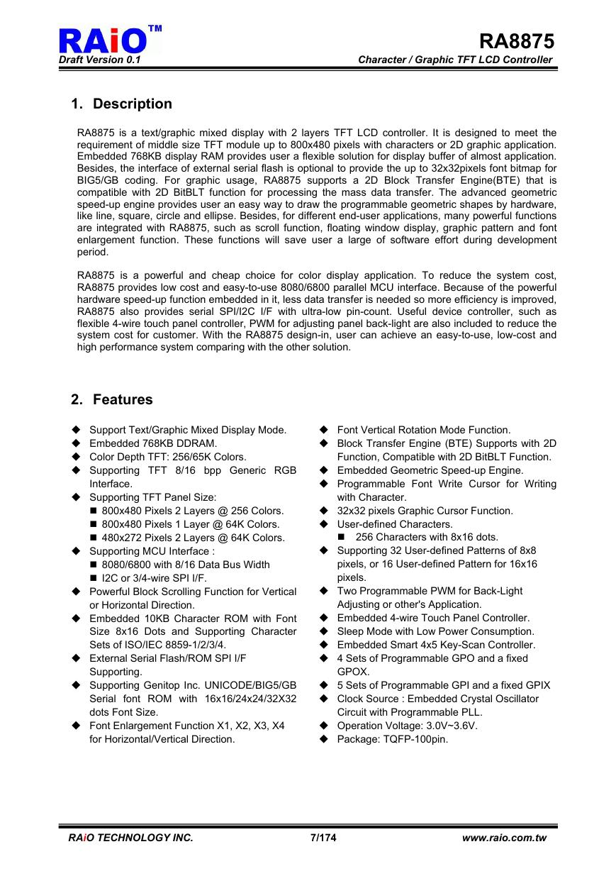
Draft Version 0.1 Character / Graphic TFT LCD Controller RA8875 1. Description RA8875 is a text/graphic mixed display with 2 layers TFT LCD controller. It is designed to meet the requirement of middle size TFT module up to 800x480 pixels with characters or 2D graphic application. Embedded 768KB display RAM provides user a flexible solution for display buffer of almost application. Besides, the interface of external serial flash is optional to provide the up to 32x32pixels font bitmap for BIG5/GB coding. For graphic usage, RA8875 supports a 2D Block Transfer Engine(BTE) that is compatible with 2D BitBLT function for processing the mass data transfer. The advanced geometric speed-up engine provides user an easy way to draw the programmable geometric shapes by hardware, like line, square, circle and ellipse. Besides, for different end-user applications, many powerful functions are integrated with RA8875, such as scroll function, floating window display, graphic pattern and font enlargement function. These functions will save user a large of software effort during development period. RA8875 is a powerful and cheap choice for color display application. To reduce the system cost, RA8875 provides low cost and easy-to-use 8080/6800 parallel MCU interface. Because of the powerful hardware speed-up function embedded in it, less data transfer is needed so more efficiency is improved, RA8875 also provides serial SPI/I2C I/F with ultra-low pin-count. Useful device controller, such as flexible 4-wire touch panel controller, PWM for adjusting panel back-light are also included to reduce the system cost for customer. With the RA8875 design-in, user can achieve an easy-to-use, low-cost and high performance system comparing with the other solution. 2. Features Support Text/Graphic Mixed Display Mode. Embedded 768KB DDRAM. Color Depth TFT: 256/65K Colors. Supporting TFT 8/16 bpp Generic RGB Interface. Supporting TFT Panel Size: 800x480 Pixels 2 Layers @ 256 Colors. 800x480 Pixels 1 Layer @ 64K Colors. 480x272 Pixels 2 Layers @ 64K Colors. Supporting MCU Interface : 8080/6800 with 8/16 Data Bus Width I2C or 3/4-wire SPI I/F. Powerful Block Scrolling Function for Vertical or Horizontal Direction. Embedded 10KB Character ROM with Font Size 8x16 Dots and Supporting Character Sets of ISO/IEC 8859-1/2/3/4. External Serial Flash/ROM SPI I/F Supporting. Supporting Genitop Inc. UNICODE/BIG5/GB Serial font ROM with 16x16/24x24/32X32 dots Font Size. Font Enlargement Function X1, X2, X3, X4 for Horizontal/Vertical Direction. Font Vertical Rotation Mode Function. Block Transfer Engine (BTE) Supports with 2D Function, Compatible with 2D BitBLT Function. Embedded Geometric Speed-up Engine. Programmable Font Write Cursor for Writing with Character. 32x32 pixels Graphic Cursor Function. User-defined Characters. 256 Characters with 8x16 dots. Supporting 32 User-defined Patterns of 8x8 pixels, or 16 User-defined Pattern for 16x16 pixels. Two Programmable PWM for Back-Light Adjusting or other's Application. Embedded 4-wire Touch Panel Controller. Sleep Mode with Low Power Consumption. Embedded Smart 4x5 Key-Scan Controller. 4 Sets of Programmable GPO and a fixed GPOX. 5 Sets of Programmable GPI and a fixed GPIX Clock Source : Embedded Crystal Oscillator Circuit with Programmable PLL. Operation Voltage: 3.0V~3.6V. Package: TQFP-100pin. RAiO TECHNOLOGY INC. 7/174 www.raio.com.tw
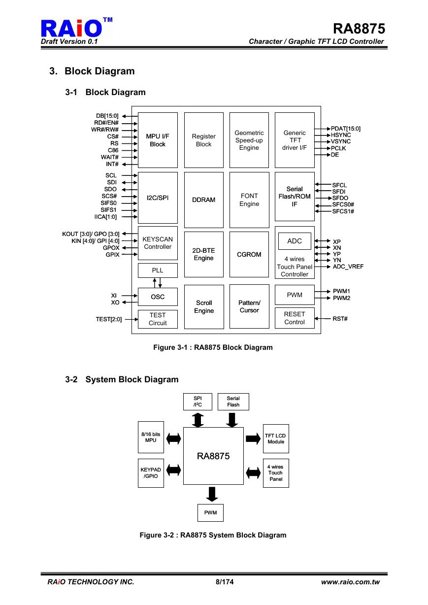
Draft Version 0.1 Character / Graphic TFT LCD Controller RA8875 PDAT[15:0] PDAT[15:0] HSYNC HSYNC VSYNC VSYNC PCLK PCLK DE DE SFCL SFCL SFDI SFDI SFDO SFDO SFCS0# SFCS0# SFCS1# SFCS1# XP XP XN XN YP YP YN YN ADC_VREF ADC_VREF PWM1 PWM1 PWM2 PWM2 RST# RST# 3. Block Diagram 3-1 Block Diagram DB[15:0] DB[15:0] RD#/EN# RD#/EN# WR#/RW# WR#/RW# CS# CS# RS RS C86 C86 WAIT# WAIT# INT# INT# SCL SCL SDI SDI SDO SDO SCS# SCS# SIFS0 SIFS0 SIFS1 SIFS1 IICA[1:0] IICA[1:0] MPU I/F MPU I/F Block Block Register Register Block Block Geometric Geometric Speed-up Speed-up Engine Engine Generic Generic TFT TFT driver I/F driver I/F I2C/SPI I2C/SPI DDRAM DDRAM FONT FONT Engine Engine Serial Serial Flash/ROM Flash/ROM IF IF KOUT [3:0]/ GPO [3:0] KOUT [3:0]/ GPO [3:0] KIN [4:0]/ GPI [4:0] KIN [4:0]/ GPI [4:0] GPOX GPOX GPIX GPIX KEYSCAN KEYSCAN Controller Controller 2D-BTE 2D-BTE Engine Engine CGROM CGROM PLL PLL OSC OSC TEST TEST Circuit Circuit XI XI XO XO TEST[2:0] TEST[2:0] Scroll Scroll Engine Engine Pattern/ Pattern/ Cursor Cursor ADC ADC 4 wires 4 wires Touch Panel Touch Panel Controller Controller PWM PWM RESET RESET Control Control Figure 3-1 : RA8875 Block Diagram 3-2 System Block Diagram SPI SPI /I2C /I2C Serial Serial Flash Flash RA8875 RA8875 TFT LCD TFT LCD Module Module 4 wires 4 wires Touch Touch Panel Panel 8/16 bits 8/16 bits MPU MPU KEYPAD KEYPAD /GPIO /GPIO PWM PWM Figure 3-2 : RA8875 System Block Diagram RAiO TECHNOLOGY INC. 8/174 www.raio.com.tw
分享到:
收藏