UM1872
User manual
Getting started with the Sub-1 GHz expansion board based on
SPSGRF-868 and SPSGRF-915 modules for STM32 Nucleo
Introduction
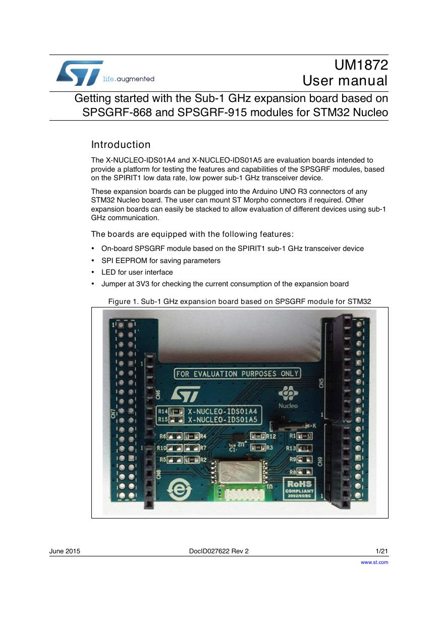
The X-NUCLEO-IDS01A4 and X-NUCLEO-IDS01A5 are evaluation boards intended to
provide a platform for testing the features and capabilities of the SPSGRF modules, based
on the SPIRIT1 low data rate, low power sub-1 GHz transceiver device.
These expansion boards can be plugged into the Arduino UNO R3 connectors of any
STM32 Nucleo board. The user can mount ST Morpho connectors if required. Other
expansion boards can easily be stacked to allow evaluation of different devices using sub-1
GHz communication.
The boards are equipped with the following features:
• On-board SPSGRF module based on the SPIRIT1 sub-1 GHz transceiver device
• SPI EEPROM for saving parameters
• LED for user interface
• Jumper at 3V3 for checking the current consumption of the expansion board
Figure 1. Sub-1 GHz expansion board based on SPSGRF module for STM32
June 2015
DocID027622 Rev 2
1/21
www.st.com
21
�
Contents
Contents
UM1872
1
2
3
4
5
6
7
8
9
Description . . . . . . . . . . . . . . . . . . . . . . . . . . . . . . . . . . . . . . . . . . . . . . . . . 3
Typical applications . . . . . . . . . . . . . . . . . . . . . . . . . . . . . . . . . . . . . . . . . . 3
1.1
1.2
Abbreviations . . . . . . . . . . . . . . . . . . . . . . . . . . . . . . . . . . . . . . . . . . . . . . . 4
Getting started . . . . . . . . . . . . . . . . . . . . . . . . . . . . . . . . . . . . . . . . . . . . . . 5
Hardware requirements . . . . . . . . . . . . . . . . . . . . . . . . . . . . . . . . . . . . . . . 5
2.1
2.2
2.3
System requirements . . . . . . . . . . . . . . . . . . . . . . . . . . . . . . . . . . . . . . . . . 6
Setting up the board . . . . . . . . . . . . . . . . . . . . . . . . . . . . . . . . . . . . . . . . . . 6
Hardware description . . . . . . . . . . . . . . . . . . . . . . . . . . . . . . . . . . . . . . . . 7
Interconnection details . . . . . . . . . . . . . . . . . . . . . . . . . . . . . . . . . . . . . . . . 7
3.1
3.2
3.3
3.4
SPI and GPIO connection options . . . . . . . . . . . . . . . . . . . . . . . . . . . . . . . 8
Current measurement . . . . . . . . . . . . . . . . . . . . . . . . . . . . . . . . . . . . . . . . 9
X-NUCLEO-IDS01Ax component placement details . . . . . . . . . . . . . . . . . 9
Component description . . . . . . . . . . . . . . . . . . . . . . . . . . . . . . . . . . . . . 11
SPSGRF-868 / SPSGRF-915 module . . . . . . . . . . . . . . . . . . . . . . . . . . . .11
4.1
4.2
SPI EEPROM . . . . . . . . . . . . . . . . . . . . . . . . . . . . . . . . . . . . . . . . . . . . . . .11
Formal Notices Required by the U.S. Federal
Communications Commission (“FCC”) . . . . . . . . . . . . . . . . . . . . . . . . 12
Formal Notices Required by the Industry Canada (“IC”) . . . . . . . . . . 13
Hardware schematic diagrams . . . . . . . . . . . . . . . . . . . . . . . . . . . . . . . 14
Bill of material . . . . . . . . . . . . . . . . . . . . . . . . . . . . . . . . . . . . . . . . . . . . . 18
Revision history . . . . . . . . . . . . . . . . . . . . . . . . . . . . . . . . . . . . . . . . . . . 20
2/21
DocID027622 Rev 2
�
UM1872
1
Description
Description
The X-NUCLEO-IDS01A4 and X-NUCLEO-IDS01A5 boards contain the module SPSGRF-
868 or SPSGRF-915 based on SPIRIT1 low data rate, low power sub-1 GHz transceiver.
The PCB layout is the same for both boards, with the only difference being the module used
with it.
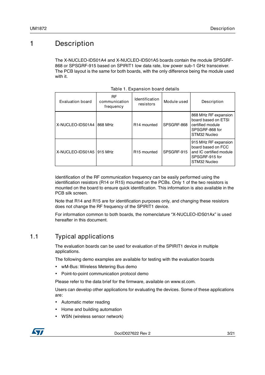
Table 1. Expansion board details
Evaluation board
communication
frequency
RF
Identification
resistors
Module used
Description
X-NUCLEO-IDS01A4 868 MHz
R14 mounted
SPSGRF-868
X-NUCLEO-IDS01A5 915 MHz
R15 mounted
SPSGRF-915
868 MHz RF expansion
board based on ETSI
certified module
SPSGRF-868 for
STM32 Nucleo
915 MHz RF expansion
board based on FCC
and IC certified module
SPSGRF-915 for
STM32 Nucleo
Identification of the RF communication frequency can be easily performed using the
identification resistors (R14 or R15) mounted on the PCBs. Only 1 of the two resistors is
mounted on the board to ensure quick identification. This information is also available in the
PCB silk screen.
Note that R14 and R15 are for identification purposes only, and changing these resistors
does not change the RF frequency of the SPIRIT1 device.
For information common to both boards, the nomenclature “X-NUCLEO-IDS01Ax” is used
hereafter in this document.
1.1
Typical applications
The evaluation boards can be used for evaluation of the SPIRIT1 device in multiple
applications.
The following demo examples are available for testing with the evaluation boards
• wM-Bus: Wireless Metering Bus demo
• Point-to-point communication protocol demo
Please refer to the data brief for the firmware, available on www.st.com.
Users can develop other applications for evaluating the devices. Some of these applications
are:
• Automatic meter reading
• Home and building automation
• WSN (wireless sensor network)
DocID027622 Rev 2
3/21
21
�
Description
UM1872
Industrial monitoring and control
•
• Wireless fire and security alarm systems
1.2
Abbreviations
Term
AMR
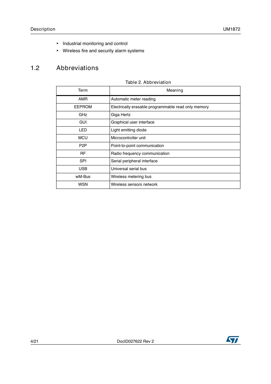
Table 2. Abbreviation
Meaning
Automatic meter reading
EEPROM
Electrically erasable programmable read only memory
GHz
GUI
LED
MCU
P2P
RF
SPI
USB
wM-Bus
WSN
Giga Hertz
Graphical user interface
Light emitting diode
Microcontroller unit
Point-to-point communication
Radio frequency communication
Serial peripheral interface
Universal serial bus
Wireless metering bus
Wireless sensors network
4/21
DocID027622 Rev 2
�
UM1872
Getting started
2
Getting started
This section describes the hardware requirements for the X-NUCLEO-IDS01Ax evaluation
boards.
2.1
Hardware requirements
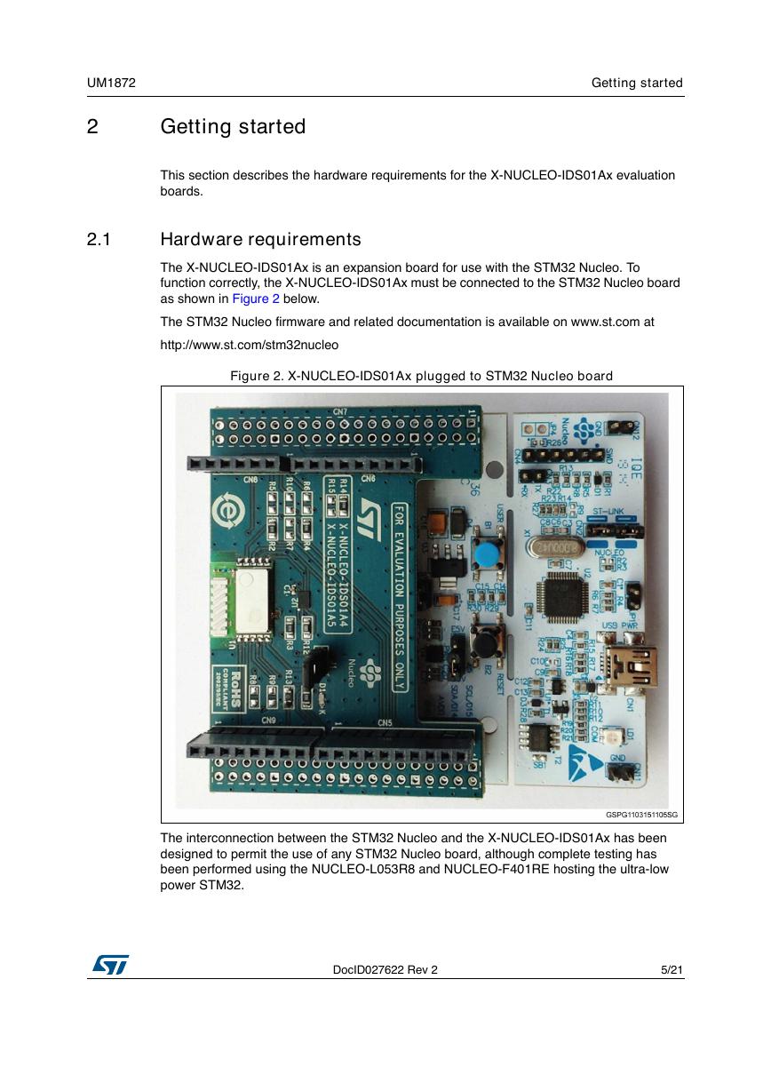
The X-NUCLEO-IDS01Ax is an expansion board for use with the STM32 Nucleo. To
function correctly, the X-NUCLEO-IDS01Ax must be connected to the STM32 Nucleo board
as shown in Figure 2 below.
The STM32 Nucleo firmware and related documentation is available on www.st.com at
http://www.st.com/stm32nucleo
Figure 2. X-NUCLEO-IDS01Ax plugged to STM32 Nucleo board
The interconnection between the STM32 Nucleo and the X-NUCLEO-IDS01Ax has been
designed to permit the use of any STM32 Nucleo board, although complete testing has
been performed using the NUCLEO-L053R8 and NUCLEO-F401RE hosting the ultra-low
power STM32.
DocID027622 Rev 2
5/21
21
�
Getting started
UM1872
2.2
System requirements
Using the Nucleo boards with the X-NUCLEO-IDS01Ax expansion board requires the
following software and hardware:
• Windows PC (XP, Vista, 7, 8) to install the firmware package
• USB type A to Mini-B USB cable to connect the Nucleo board to the PC
Installation of the board firmware package and the wM-Bus graphical user interface utility on
the user's PC requires the following:
• 128 MB of RAM
• Approximately 40 MB of hard disk space for the firmware
• Approximately 15 MB of hard disk space for the wM-Bus GUI
The use of the wM-Bus concentrator with the GUI requires additional boards to be
connected to the PC. The GUI can be used to check the wM-Bus communication example.
The Nucleo board acts as a meter and the STEVAL-IKR001Vx board connected to the PC
acts as a concentrator. Please note that the wM-Bus example is valid only for X-NUCLEO-
IDS01A4 (868 MHz version).
2.3
Setting up the board
Perform the following steps to set up the board:
1. Check that the jumper on the J1 connector is connected. This jumper provides the
required voltage to the devices on the board
2. Connect the X-NUCLEO-IDS01Ax to the Nucleo board from the top, as shown in
Figure 2.
3. Power the Nucleo board using the Mini-B USB cable
4. Program the firmware in the STM32 on the Nucleo board using the firmware example
provided
5. Reset the MCU board using the reset button on the Nucleo board
6. The evaluation kit is ready for use
6/21
DocID027622 Rev 2
�
UM1872
Hardware description
3
Hardware description
This section describes the X-NUCLEO-IDS01Ax features and provides information which
could be useful to understand the board schematics.
3.1
Interconnection details
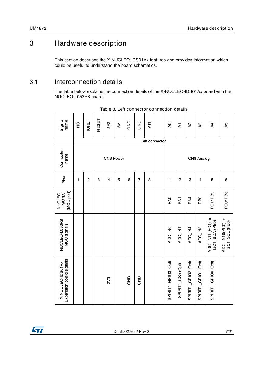
The table below explains the connection details of the X-NUCLEO-IDS01Ax board with the
NUCLEO-L053R8 board.
Table 3. Left connector connection details
l
a
n
g
S
i
e
m
a
n
C
N
F
E
R
O
I
T
E
S
E
R
3
V
3
V
5
D
N
G
D
N
G
N
V
I
0
A
1
A
2
A
3
A
4
A
5
A
Left connector
CN6 Power
CN8 Analog
1
2
3
4
5
6
7
8
1
2
3
4
5
6
0
A
P
1
A
P
4
A
P
0
B
P
9
B
P
/
1
C
P
r
o
)
1
C
P
(
1
1
N
I
_
C
D
A
)
9
B
P
(
A
D
S
_
1
C
2
I
8
B
P
/
0
C
P
r
o
)
0
C
P
(
0
1
N
I
_
C
D
A
)
8
B
P
(
L
C
S
_
1
C
2
I
0
N
I
_
C
D
A
)
t
p
O
(
I
3
O
P
G
_
1
T
R
P
S
I
I
1
N
I
_
C
D
A
)
t
p
O
(
n
S
C
_
1
T
R
P
S
I
I
3
V
3
D
N
G
D
N
G
4
N
I
_
C
D
A
8
N
I
_
C
D
A
)
t
p
O
(
)
t
p
O
(
)
t
p
O
(
I
2
O
P
G
_
1
T
R
P
S
I
I
I
1
O
P
G
_
1
T
R
P
S
I
I
I
0
O
P
G
_
1
T
R
P
S
I
I
r
o
t
c
e
n
n
o
C
e
m
a
n
#
n
P
i
-
O
E
L
C
U
N
8
R
3
5
0
L
)
t
r
o
p
U
C
M
(
8
R
3
5
0
L
-
O
E
L
C
U
N
x
A
1
0
S
D
I
-
O
E
L
C
U
N
X
-
l
i
s
a
n
g
s
U
C
M
l
i
s
a
n
g
s
d
r
a
o
b
i
n
o
s
n
a
p
x
E
DocID027622 Rev 2
7/21
21
�
Hardware description
UM1872
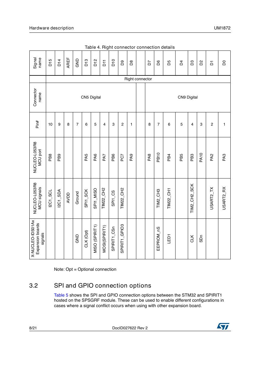
Table 4. Right connector connection details
l
a
n
g
S
i
e
m
a
n
5
1
D
4
1
D
F
E
R
A
D
N
G
3
1
D
2
1
D
1
1
D
0
1
D
9
D
8
D
7
D
6
D
5
D
4
D
3
D
2
D
1
D
0
D
Right connector
CN5 Digital
CN9 Digital
10
9
8
7
6
5
4
3
2
1
8
7
6
5
4
3
2
1
r
o
t
c
e
n
n
o
C
e
m
a
n
#
n
P
i
t
r
o
p
U
C
M
8
B
P
9
B
P
5
A
P
6
A
P
7
A
P
6
B
P
7
C
P
9
A
P
8
A
P
0
1
B
P
4
B
P
5
B
P
3
B
P
0
1
A
P
2
A
P
3
A
P
8
R
3
5
0
L
-
O
E
L
C
U
N
8
R
3
5
0
L
-
O
E
L
C
U
N
l
i
s
a
n
g
s
U
C
M
L
C
S
_
1
C
2
I
A
D
S
_
1
C
2
I
D
D
V
A
d
n
u
o
r
G
D
N
G
K
C
S
_
1
I
P
S
)
t
p
O
(
K
L
C
I
O
S
M
_
1
I
P
S
2
H
C
_
2
2
M
T
I
S
C
_
1
I
P
S
2
H
C
_
2
2
M
T
I
I
)
1
T
R
P
S
I
(
O
S
M
I
I
)
1
T
R
P
S
I
(
I
S
O
M
n
S
C
_
1
T
R
P
S
I
I
I
3
O
P
G
_
1
T
R
P
S
I
I
K
C
S
_
2
H
C
_
2
M
T
I
X
T
_
2
T
R
A
S
U
X
R
_
2
T
R
A
S
U
K
L
C
n
D
S
1
H
C
_
2
2
M
T
I
1
D
E
L
3
H
C
_
2
M
T
I
S
n
_
M
O
R
P
E
E
x
A
1
0
S
D
I
-
O
E
L
C
U
N
X
-
s
d
r
a
o
b
n
o
s
n
a
p
x
E
i
l
s
a
n
g
s
i
Note: Opt = Optional connection
3.2
SPI and GPIO connection options
Table 5 shows the SPI and GPIO connection options between the STM32 and SPIRIT1
hosted on the SPSGRF module. These can be used to enable different configurations in
cases where a signal conflict occurs when using with other expansion board.
8/21
DocID027622 Rev 2
�


 V2版本原理图(Capacitive-Fingerprint-Reader-Schematic_V2).pdf
 摄像头工作原理.doc
 VL53L0X简要说明(En.FLVL53L00216).pdf
 原理图(DVK720-Schematic).pdf
 原理图(Pico-Clock-Green-Schdoc).pdf
 原理图(RS485-CAN-HAT-B-schematic).pdf
 File:SIM7500_SIM7600_SIM7800 Series_SSL_Application Note_V2.00.pdf
 ADS1263(Ads1262).pdf
 原理图(Open429Z-D-Schematic).pdf
 用户手册(Capacitive_Fingerprint_Reader_User_Manual_CN).pdf
 CY7C68013A(英文版)(CY7C68013A).pdf
 TechnicalReference_Dem.pdf