logo资料库

ST25R3911数据手册(英文)(St25r3911b_EN).pdf

第1页 / 共114页
第2页 / 共114页
第3页 / 共114页
第4页 / 共114页
第5页 / 共114页
第6页 / 共114页
第7页 / 共114页
第8页 / 共114页
资料共114页,剩余部分请下载后查看
1 Functional overview
1.1 Block diagram
1.1.1 Transmitter
1.1.2 Receiver
1.1.3 Phase and amplitude detector
1.1.4 A/D converter
1.1.5 Capacitive sensor
1.1.6 External field detector
1.1.7 Quartz crystal oscillator
1.1.8 Power supply regulators
1.1.9 POR and Bias
1.1.10 RC oscillator and Wake-Up timer
1.1.11 ISO-14443 and NFCIP-1 framing
1.1.12 FIFO
1.1.13 Control logic
1.1.14 SPI
1.2 Application information
1.2.1 Operating modes
1.2.2 Transmitter
1.2.3 Receiver
1.2.4 Capacitive sensor
1.2.5 Wake-up mode
1.2.6 Quartz crystal oscillator
1.2.7 Timers
1.2.8 A/D converter
1.2.9 Phase and amplitude detector
1.2.10 External field detector
1.2.11 Power supply system
1.2.12 Communication with an external microcontroller
1.2.13 Direct commands
1.2.14 Start timers
1.2.15 Test access
1.2.16 Power-up sequence
1.2.17 Reader operation
1.2.18 FeliCa™ reader mode
1.2.19 NFCIP-1 operation
1.2.20 AM modulation depth: definition and calibration
1.2.21 Antenna tuning
1.2.22 Stream mode and transparent mode
1.3 Registers
1.3.1 IO configuration register 1
1.3.2 IO configuration register 2
1.3.3 Operation control register
1.3.4 Mode definition register
1.3.5 Bit rate definition register
1.3.6 ISO14443A and NFC 106kb/s settings register
1.3.7 ISO14443B settings register 1
1.3.8 ISO14443B and FeliCa settings register
1.3.9 Stream mode definition register
1.3.10 Auxiliary definition register
1.3.11 Receiver configuration register 1
1.3.12 Receiver configuration register 2
1.3.13 Receiver configuration register 3
1.3.14 Receiver configuration register 4
1.3.15 Mask receive timer register
1.3.16 No-response timer register 1
1.3.17 No-response timer register 2
1.3.18 General purpose and no-response timer control register
1.3.19 General purpose timer register 1
1.3.20 General purpose timer register 2
1.3.21 Mask main interrupt register
1.3.22 Mask timer and NFC interrupt register
1.3.23 Mask error and wake-up interrupt register
1.3.24 Main interrupt register
1.3.25 Timer and NFC interrupt register
1.3.26 Error and wake-up interrupt register
1.3.27 FIFO status register 1
1.3.28 FIFO status register 2
1.3.29 Collision display register
1.3.30 Number of transmitted bytes register 1
1.3.31 Number of transmitted bytes register 2
1.3.32 NFCIP bit rate detection display register
1.3.33 A/D converter output register
1.3.34 Antenna calibration control register
1.3.35 Antenna calibration target register
1.3.36 Antenna calibration display register
1.3.37 AM modulation depth control register
1.3.38 AM modulation depth display register
1.3.39 RFO AM modulated level definition register
1.3.40 RFO normal level definition register
1.3.41 External field detector threshold register
1.3.42 Regulator voltage control register
1.3.43 Regulator and timer display register
1.3.44 RSSI display register
1.3.45 Gain reduction state register
1.3.46 Capacitive sensor control register
1.3.47 Capacitive sensor display register
1.3.48 Auxiliary display register
1.3.49 Wake-up timer control register
1.3.50 Amplitude measurement configuration register
1.3.51 Amplitude measurement reference register
1.3.52 Amplitude measurement auto-averaging display register
1.3.53 Amplitude measurement display register
1.3.54 Phase measurement configuration register
1.3.55 Phase measurement reference register
1.3.56 Phase measurement auto-averaging display register
1.3.57 Phase measurement display register
1.3.58 Capacitance measurement configuration register
1.3.59 Capacitance measurement reference register
1.3.60 Capacitance measurement auto-averaging display register
1.3.61 Capacitance measurement display register
1.3.62 IC identity register
2 Pinouts and pin description
3 Electrical characteristics
3.1 Absolute maximum ratings
3.2 Operating conditions
3.3 DC/AC characteristics for digital inputs and outputs
3.3.1 CMOS inputs
3.3.2 CMOS outputs
3.4 Electrical specifications
3.5 Typical operating characteristics
3.5.1 Thermal resistance and maximum power dissipation
4 Package information
4.1 QFN32 package information
5 Ordering information
Revision history
Contents
List of tables
List of figures
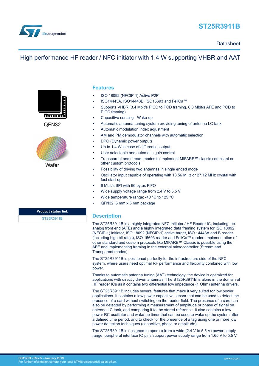
High performance HF reader / NFC initiator with 1.4 W supporting VHBR and AAT ST25R3911B Datasheet QFN32 Wafer Product status link ST25R3911B Features • • • ISO 18092 (NFCIP-1) Active P2P ISO14443A, ISO14443B, ISO15693 and FeliCa™ Supports VHBR (3.4 Mbit/s PICC to PCD framing, 6.8 Mbit/s AFE and PCD to PICC framing) Capacitive sensing - Wake-up Automatic antenna tuning system providing tuning of antenna LC tank Automatic modulation index adjustment AM and PM demodulator channels with automatic selection DPO (Dynamic power output) Up to 1.4 W in case of differential output User selectable and automatic gain control Transparent and stream modes to implement MIFARE™ classic compliant or other custom protocols Possibility of driving two antennas in single ended mode Oscillator input capable of operating with 13.56 MHz or 27.12 MHz crystal with fast start-up 6 Mbit/s SPI with 96 bytes FIFO • • • • • • • • • • • • Wide supply voltage range from 2.4 V to 5.5 V • Wide temperature range: -40 °C to 125 °C • QFN32, 5 mm x 5 mm package Description The ST25R3911B is a highly integrated NFC Initiator / HF Reader IC, including the analog front end (AFE) and a highly integrated data framing system for ISO 18092 (NFCIP-1) initiator, ISO 18092 (NFCIP-1) active target, ISO 14443A and B reader (including high bit rates), ISO 15693 reader and FeliCa™ reader. Implementation of other standard and custom protocols like MIFARE™ Classic is possible using the AFE and implementing framing in the external microcontroller (Stream and Transparent modes). The ST25R3911B is positioned perfectly for the infrastructure side of the NFC system, where users need optimal RF performance and flexibility combined with low power. Thanks to automatic antenna tuning (AAT) technology, the device is optimized for applications with directly driven antennas. The ST25R3911B is alone in the domain of HF reader ICs as it contains two differential low impedance (1 Ohm) antenna drivers. The ST25R3911B includes several features that make it very suited for low power applications. It contains a low power capacitive sensor that can be used to detect the presence of a card without switching on the reader field. The presence of a card can also be detected by performing a measurement of amplitude or phase of signal on antenna LC tank, and comparing it to the stored reference. It also contains a low power RC oscillator and wake-up timer that can be used to wake up the system after a defined time period, and to check for the presence of a tag using one or more low power detection techniques (capacitive, phase or amplitude). The ST25R3911B is designed to operate from a wide (2.4 V to 5.5 V) power supply range; peripheral interface IO pins support power supply range from 1.65 V to 5.5 V. DS11793 - Rev 5 - January 2019 For further information contact your local STMicroelectronics sales office. www.st.com
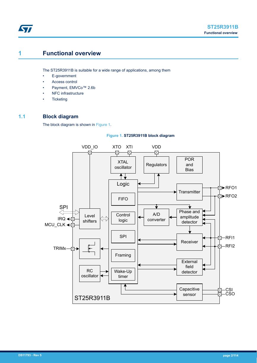
ST25R3911B Functional overview 1 Functional overview The ST25R3911B is suitable for a wide range of applications, among them • • • • • E-government Access control Payment, EMVCo™ 2.6b NFC infrastructure Ticketing 1.1 Block diagram The block diagram is shown in Figure 1. Figure 1. ST25R3911B block diagram VDD_IO XTO XTI VDD XTAL oscillator Logic FIFO Control logic SPI Framing Level shifters SPI IRQ MCU_CLK TRIMx RC oscillator Wake-Up timer ST25R3911B Regulators POR and Bias Transmitter A/D converter Phase and amplitude detector Receiver External field detector RFO1 RFO2 RFI1 RFI2 Capacitive sensor CSI CSO DS11793 - Rev 5 page 2/114
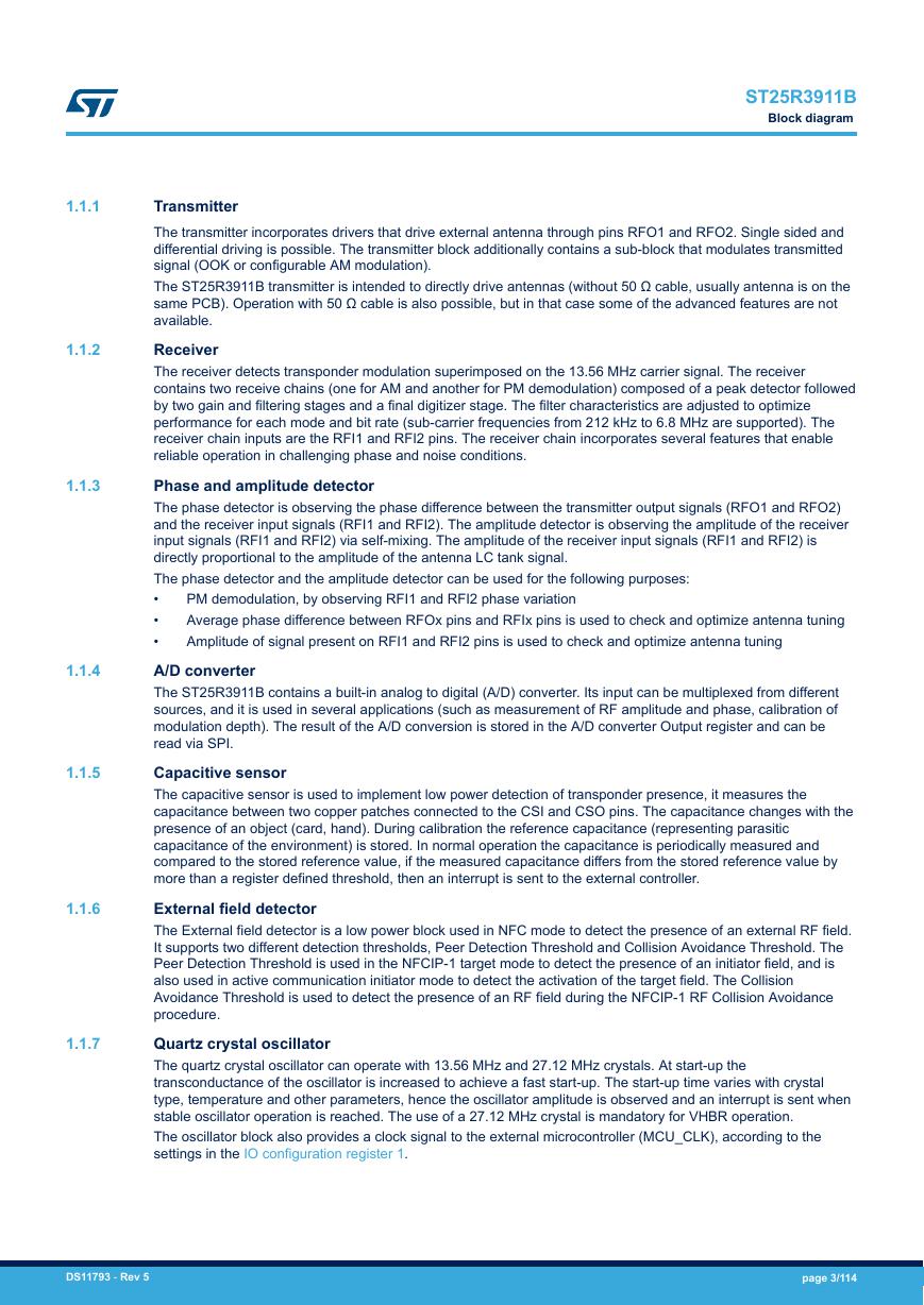
ST25R3911B Block diagram 1.1.1 1.1.2 1.1.3 1.1.4 1.1.5 1.1.6 1.1.7 PM demodulation, by observing RFI1 and RFI2 phase variation Average phase difference between RFOx pins and RFIx pins is used to check and optimize antenna tuning Amplitude of signal present on RFI1 and RFI2 pins is used to check and optimize antenna tuning Transmitter The transmitter incorporates drivers that drive external antenna through pins RFO1 and RFO2. Single sided and differential driving is possible. The transmitter block additionally contains a sub-block that modulates transmitted signal (OOK or configurable AM modulation). The ST25R3911B transmitter is intended to directly drive antennas (without 50 Ω cable, usually antenna is on the same PCB). Operation with 50 Ω cable is also possible, but in that case some of the advanced features are not available. Receiver The receiver detects transponder modulation superimposed on the 13.56 MHz carrier signal. The receiver contains two receive chains (one for AM and another for PM demodulation) composed of a peak detector followed by two gain and filtering stages and a final digitizer stage. The filter characteristics are adjusted to optimize performance for each mode and bit rate (sub-carrier frequencies from 212 kHz to 6.8 MHz are supported). The receiver chain inputs are the RFI1 and RFI2 pins. The receiver chain incorporates several features that enable reliable operation in challenging phase and noise conditions. Phase and amplitude detector The phase detector is observing the phase difference between the transmitter output signals (RFO1 and RFO2) and the receiver input signals (RFI1 and RFI2). The amplitude detector is observing the amplitude of the receiver input signals (RFI1 and RFI2) via self-mixing. The amplitude of the receiver input signals (RFI1 and RFI2) is directly proportional to the amplitude of the antenna LC tank signal. The phase detector and the amplitude detector can be used for the following purposes: • • • A/D converter The ST25R3911B contains a built-in analog to digital (A/D) converter. Its input can be multiplexed from different sources, and it is used in several applications (such as measurement of RF amplitude and phase, calibration of modulation depth). The result of the A/D conversion is stored in the A/D converter Output register and can be read via SPI. Capacitive sensor The capacitive sensor is used to implement low power detection of transponder presence, it measures the capacitance between two copper patches connected to the CSI and CSO pins. The capacitance changes with the presence of an object (card, hand). During calibration the reference capacitance (representing parasitic capacitance of the environment) is stored. In normal operation the capacitance is periodically measured and compared to the stored reference value, if the measured capacitance differs from the stored reference value by more than a register defined threshold, then an interrupt is sent to the external controller. External field detector The External field detector is a low power block used in NFC mode to detect the presence of an external RF field. It supports two different detection thresholds, Peer Detection Threshold and Collision Avoidance Threshold. The Peer Detection Threshold is used in the NFCIP-1 target mode to detect the presence of an initiator field, and is also used in active communication initiator mode to detect the activation of the target field. The Collision Avoidance Threshold is used to detect the presence of an RF field during the NFCIP-1 RF Collision Avoidance procedure. Quartz crystal oscillator The quartz crystal oscillator can operate with 13.56 MHz and 27.12 MHz crystals. At start-up the transconductance of the oscillator is increased to achieve a fast start-up. The start-up time varies with crystal type, temperature and other parameters, hence the oscillator amplitude is observed and an interrupt is sent when stable oscillator operation is reached. The use of a 27.12 MHz crystal is mandatory for VHBR operation. The oscillator block also provides a clock signal to the external microcontroller (MCU_CLK), according to the settings in the IO configuration register 1. DS11793 - Rev 5 page 3/114
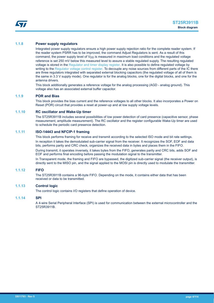
ST25R3911B Block diagram 1.1.8 1.1.9 1.1.10 1.1.11 1.1.12 1.1.13 1.1.14 Power supply regulators Integrated power supply regulators ensure a high power supply rejection ratio for the complete reader system. If the reader system PSRR has to be improved, the command Adjust Regulators is sent. As a result of this command, the power supply level of VDD is measured in maximum load conditions and the regulated voltage reference is set 250 mV below this measured level to assure a stable regulated supply. The resulting regulated voltage is stored in the Regulator and timer display register. It is also possible to define regulated voltage by writing to the Regulator voltage control register. To decouple any noise sources from different parts of the IC there are three regulators integrated with separated external blocking capacitors (the regulated voltage of all of them is the same in 3.3 V supply mode). One regulator is for the analog blocks, one for the digital blocks, and one for the antenna drivers. This block additionally generates a reference voltage for the analog processing (AGD - analog ground). This voltage also has an associated external buffer capacitor. POR and Bias This block provides the bias current and the reference voltages to all other blocks. It also incorporates a Power on Reset (POR) circuit that provides a reset at power-up and at low supply voltage levels. RC oscillator and Wake-Up timer The ST25R3911B includes several possibilities of low power detection of card presence (capacitive sensor, phase measurement, amplitude measurement). The RC oscillator and the register configurable Wake-Up timer are used to schedule the periodic card presence detection. ISO-14443 and NFCIP-1 framing This block performs framing for receive and transmit according to the selected ISO mode and bit rate settings. In reception it takes the demodulated sub-carrier signal from the receiver. It recognizes the SOF, EOF and data bits, performs parity and CRC check, organizes the received data in bytes and places them in the FIFO. During transmit, it operates inversely, it takes bytes from the FIFO, generates parity and CRC bits, adds SOF and EOF and performs final encoding before passing the modulation signal to the transmitter. In Transparent mode, the framing and FIFO are bypassed, the digitized sub-carrier signal (the receiver output), is directly sent to the MISO pin, and the signal applied to the MOSI pin is directly used to modulate the transmitter. FIFO The ST25R3911B contains a 96-byte FIFO. Depending on the mode, it contains either data that has been received or data to be transmitted. Control logic The control logic contains I/O registers that define operation of device. SPI A 4-wire Serial Peripheral Interface (SPI) is used for communication between the external microcontroller and the ST25R3911B. DS11793 - Rev 5 page 4/114
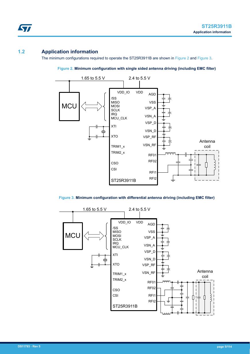
ST25R3911B Application information 1.2 Application information The minimum configurations required to operate the ST25R3911B are shown in Figure 2 and Figure 3. Figure 2. Minimum configuration with single sided antenna driving (including EMC filter) 1.65 to 5.5 V 2.4 to 5.5 V VDD_IO VDD AGD VSS VSP_A VSN_A VSP_D MCU /SS MISO MOSI SCLK IRQ MCU_CLK XTI XTO TRIM1_x TRIM2_x CSO CSI ST25R3911B Antenna coil VSN_D VSP_RF VSN_RF RF01 RF02 RFI1 RFI2 Figure 3. Minimum configuration with differential antenna driving (including EMC filter) 1.65 to 5.5 V 2.4 to 5.5 V VDD_IO VDD AGD VSS VSP_A VSN_A VSP_D MCU /SS MISO MOSI SCLK IRQ MCU_CLK XTI XTO TRIM1_x TRIM2_x CSO CSI ST25R3911B VSN_D VSP_RF VSN_RF RF01 RF02 RFI1 RFI2 Antenna coil DS11793 - Rev 5 page 5/114
1.2.1 1.2.2 ST25R3911B Application information Operating modes The ST25R3911B operating mode is defined by the contents of the Operation control register. At power-up all bits of the Operation control register are set to 0, the ST25R3911B is in Power-down mode. In this mode AFE static power consumption is minimized, only the POR and part of the bias are active, while the regulators are transparent and are not operating. The SPI is still functional in this mode so all settings of ISO mode definition and configuration registers can be done. Control bit en (bit 7 of the Operation control register) is controlling the quartz crystal oscillator and regulators. When this bit is set, the device enters in Ready mode. In this mode the quartz crystal oscillator and regulators are enabled. An interrupt is sent to inform the microcontroller when the oscillator frequency is stable. Enable of receiver and transmitter are separated so it is possible to operate one without switching on the other (control bits rx_en and tx_en). In some cases this may be useful, if the reader field has to be maintained and there is no transponder response expected, the receiver can be switched-off to save current. Another example is the NFCIP-1 active communication receive mode in which the RF field is generated by the initiator and only the receiver operates. Asserting the Operation control register bit wu while the other bits are set to 0 puts the ST25R3911B into the Wake-Up mode that is used to perform low power detection of card presence. In this mode the low power RC oscillator and register configurable Wake-Up timer are used to schedule periodic measurement(s). When a difference of the measured value vs. the predefined reference is detected an interrupt is sent to wake-up the microcontroller. Transmitter The transmitter contains two identical push-pull driver blocks connected to the pins RFO1 and RFO2. These drivers are differentially driving the external antenna LC tank. It is also possible to operate only one of the two drivers by setting the IO configuration register 1 bit single to 1. Each driver is composed of eight segments having binary weighted output resistance. The MSB segment typical ON resistance is 2 Ω, when all segments are turned on; the output resistance is typically 1 Ω. All segments are turned on to define the normal transmission (non- modulated) level. It is also possible to switch off certain segments when driving the non-modulated level to reduce the amplitude of the signal on the antenna and/or to reduce the antenna Q factor without making any hardware changes. The RFO normal level definition register defines which segments are turned on to define the normal transmission (non-modulated) level. Default setting is that all segments are turned on. Using the single driver mode the number of the antenna LC tank components (and therefore the cost) is halved, but also the output power is reduced. In single mode it is possible to connect two antenna LC tanks to the two RFO outputs and multiplex between them by controlling the IO configuration register 1 bit rfo2. In order to transmit the data the transmitter output level needs to be modulated. Both AM and OOK modulation are supported. The type of modulation is defined by setting the bit tr_am in the Auxiliary definition register. During the OOK modulation (for example ISO14443A) the transmitter drivers stop driving the carrier frequency. As consequence the amplitude of the antenna LC tank oscillation decays, the time constant of the decay is defined with the LC tank Q factor. The decay time in case of OOK modulation can be shortened by asserting the Auxiliary definition register bit ook_hr. When this bit is set to logic one the drivers are put in tristate during the OOK modulation. AM modulation (for example ISO14443B) is done by increasing the output driver impedance during the modulation time. This is done by reducing the number of driver segments that are turned on. The AM modulated level can be automatically adjusted to the target modulation depth by defining the target modulation depth in the AM modulation depth: definition and calibration and sending the Calibrate Modulation Depth direct command. Refer to Section 1.2.20 AM modulation depth: definition and calibration for further details. Slow transmitter ramping When the transmitter is enabled it starts to drive the antenna LC tank with full power, the ramping of the field emitted by antenna is defined by antenna LC tank Q factor. However there are some reader systems where the reader field has to ramp up with a longer transition time when it is enabled. The STIF (Syndicat des transports d'Ile de France) specification requires a transition time from 10% to 90% of field longer than or equal to 10 μs.The ST25R3911B supports that feature. It is realized by collapsing VSP_RF regulated voltage when transmitter is disabled and ramping it when transmitter is enabled. Typical transition time is 15 μs at 3 V supply and 20 μs at 5 V supply. Procedure to implement the slow transition: 1. When transmitter is disabled set IO configuration register 2 bit slow_up to 1. Keep this state for at least 2 ms to allow discharge of VSP_RF. DS11793 - Rev 5 page 6/114
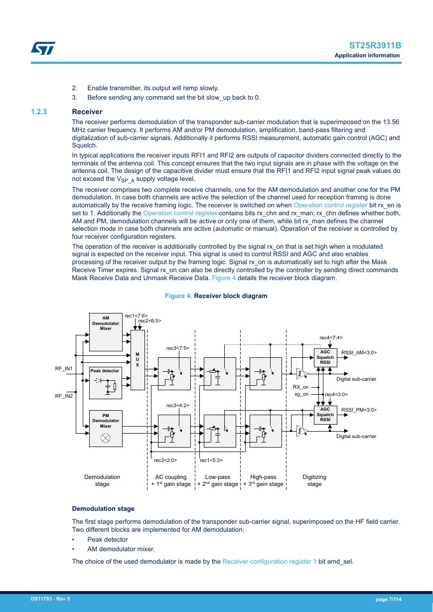
ST25R3911B Application information 1.2.3 Enable transmitter, its output will ramp slowly. Before sending any command set the bit slow_up back to 0. 2. 3. Receiver The receiver performs demodulation of the transponder sub-carrier modulation that is superimposed on the 13.56 MHz carrier frequency. It performs AM and/or PM demodulation, amplification, band-pass filtering and digitalization of sub-carrier signals. Additionally it performs RSSI measurement, automatic gain control (AGC) and Squelch. In typical applications the receiver inputs RFI1 and RFI2 are outputs of capacitor dividers connected directly to the terminals of the antenna coil. This concept ensures that the two input signals are in phase with the voltage on the antenna coil. The design of the capacitive divider must ensure that the RFI1 and RFI2 input signal peak values do not exceed the VSP_A supply voltage level. The receiver comprises two complete receive channels, one for the AM demodulation and another one for the PM demodulation. In case both channels are active the selection of the channel used for reception framing is done automatically by the receive framing logic. The receiver is switched on when Operation control register bit rx_en is set to 1. Additionally the Operation control register contains bits rx_chn and rx_man; rx_chn defines whether both, AM and PM, demodulation channels will be active or only one of them, while bit rx_man defines the channel selection mode in case both channels are active (automatic or manual). Operation of the receiver is controlled by four receiver configuration registers. The operation of the receiver is additionally controlled by the signal rx_on that is set high when a modulated signal is expected on the receiver input. This signal is used to control RSSI and AGC and also enables processing of the receiver output by the framing logic. Signal rx_on is automatically set to high after the Mask Receive Timer expires. Signal rx_on can also be directly controlled by the controller by sending direct commands Mask Receive Data and Unmask Receive Data. Figure 4 details the receiver block diagram. Figure 4. Receiver block diagram AM Demodulator Mixer RF_IN1 Peak detector RF_IN2 PM Demodulator Mixer rec1<7:6> rec2<6:5> rec3<7:5> M U X rec3<4:2> rec4<7:4> RSSI_AM<3:0> AGC Squelch RSSI Digital sub-carrier RX_on sg_on rec4<3:0> AGC Squelch RSSI RSSI_PM<3:0> Digital sub-carrier rec3<2:0> rec1<5:3> Demodulation stage AC coupling + 1st gain stage Low-pass + 2nd gain stage High-pass + 3rd gain stage Digitizing stage Demodulation stage The first stage performs demodulation of the transponder sub-carrier signal, superimposed on the HF field carrier. Two different blocks are implemented for AM demodulation: • • The choice of the used demodulator is made by the Receiver configuration register 1 bit amd_sel. Peak detector AM demodulator mixer. DS11793 - Rev 5 page 7/114
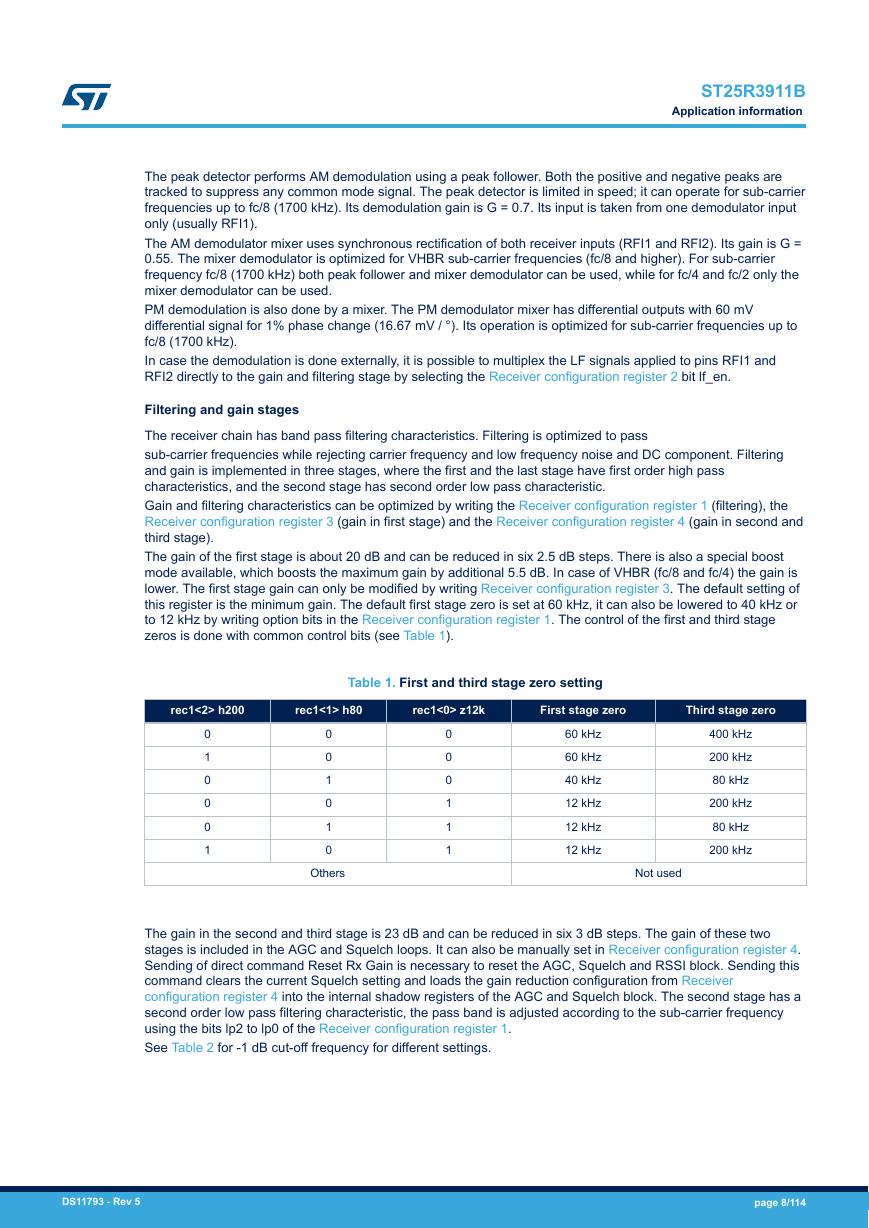
ST25R3911B Application information The peak detector performs AM demodulation using a peak follower. Both the positive and negative peaks are tracked to suppress any common mode signal. The peak detector is limited in speed; it can operate for sub-carrier frequencies up to fc/8 (1700 kHz). Its demodulation gain is G = 0.7. Its input is taken from one demodulator input only (usually RFI1). The AM demodulator mixer uses synchronous rectification of both receiver inputs (RFI1 and RFI2). Its gain is G = 0.55. The mixer demodulator is optimized for VHBR sub-carrier frequencies (fc/8 and higher). For sub-carrier frequency fc/8 (1700 kHz) both peak follower and mixer demodulator can be used, while for fc/4 and fc/2 only the mixer demodulator can be used. PM demodulation is also done by a mixer. The PM demodulator mixer has differential outputs with 60 mV differential signal for 1% phase change (16.67 mV / °). Its operation is optimized for sub-carrier frequencies up to fc/8 (1700 kHz). In case the demodulation is done externally, it is possible to multiplex the LF signals applied to pins RFI1 and RFI2 directly to the gain and filtering stage by selecting the Receiver configuration register 2 bit lf_en. Filtering and gain stages The receiver chain has band pass filtering characteristics. Filtering is optimized to pass sub-carrier frequencies while rejecting carrier frequency and low frequency noise and DC component. Filtering and gain is implemented in three stages, where the first and the last stage have first order high pass characteristics, and the second stage has second order low pass characteristic. Gain and filtering characteristics can be optimized by writing the Receiver configuration register 1 (filtering), the Receiver configuration register 3 (gain in first stage) and the Receiver configuration register 4 (gain in second and third stage). The gain of the first stage is about 20 dB and can be reduced in six 2.5 dB steps. There is also a special boost mode available, which boosts the maximum gain by additional 5.5 dB. In case of VHBR (fc/8 and fc/4) the gain is lower. The first stage gain can only be modified by writing Receiver configuration register 3. The default setting of this register is the minimum gain. The default first stage zero is set at 60 kHz, it can also be lowered to 40 kHz or to 12 kHz by writing option bits in the Receiver configuration register 1. The control of the first and third stage zeros is done with common control bits (see Table 1). rec1<2> h200 rec1<1> h80 rec1<0> z12k First stage zero Third stage zero Table 1. First and third stage zero setting 0 1 0 0 0 1 0 0 1 0 1 0 Others 0 0 0 1 1 1 60 kHz 60 kHz 40 kHz 12 kHz 12 kHz 12 kHz 400 kHz 200 kHz 80 kHz 200 kHz 80 kHz 200 kHz Not used The gain in the second and third stage is 23 dB and can be reduced in six 3 dB steps. The gain of these two stages is included in the AGC and Squelch loops. It can also be manually set in Receiver configuration register 4. Sending of direct command Reset Rx Gain is necessary to reset the AGC, Squelch and RSSI block. Sending this command clears the current Squelch setting and loads the gain reduction configuration from Receiver configuration register 4 into the internal shadow registers of the AGC and Squelch block. The second stage has a second order low pass filtering characteristic, the pass band is adjusted according to the sub-carrier frequency using the bits lp2 to lp0 of the Receiver configuration register 1. See Table 2 for -1 dB cut-off frequency for different settings. DS11793 - Rev 5 page 8/114
分享到:
收藏