Data sheet
BMP280
Digital Pressure Sensor
Bosch Sensortec
BMP280: Data sheet
Document revision
1.12
Document release date
July 11th, 2014
Document number
BST-BMP280-DS001-10
Technical reference code(s)
0 273 300 354
Notes
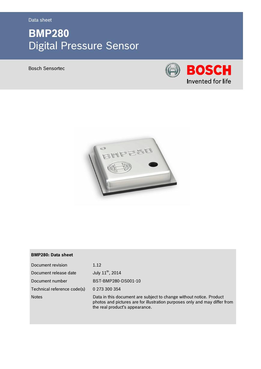
Data in this document are subject to change without notice. Product
photos and pictures are for illustration purposes only and may differ from
the real product’s appearance.
�
Datasheet
BMP280 Digital Pressure Sensor
Page 2
BMP280
DIGITAL PRESSURE SENSOR
Key parameters
Pressure range
Package
300 … 1100 hPa
(equiv. to +9000…-500 m above/below sea level)
8-pin LGA metal-lid
Footprint : 2.0 × 2.5 mm², height: 0.95 mm
Relative accuracy
(950 … 1050hPa @25°C)
±0.12 hPa, equiv. to ±1 m
Absolute accuracy
(950 ...1050 hPa, 0 ...+40 °C)
typ. ±1 hPa
Temperature coefficient offset 1.5 Pa/K, equiv. to 12.6 cm/K
(25 ... 40°C @900hPa)
Digital interfaces
I²C (up to 3.4 MHz)
SPI (3 and 4 wire, up to 10 MHz)
Current consumption
2.7µA @ 1 Hz sampling rate
Temperature range
-40 … +85 °C
RoHS compliant, halogen-free
MSL 1
Typical applications
Enhancement of GPS navigation
(e.g. time-to-first-fix improvement, dead-reckoning, slope detection)
Indoor navigation (floor detection, elevator detection)
Outdoor navigation, leisure and sports applications
Weather forecast
Health care applications (e.g. spirometry)
Vertical velocity indication (e.g. rise/sink speed)
Target devices
Handsets such as mobile phones, tablet PCs, GPS devices
Navigation systems
Portable health care devices
Home weather stations
Flying toys
Watches
BST-BMP280-DS001-10 | Revision 1.12 | July 2014
Bosch Sensortec
© Bosch Sensortec GmbH reserves all rights even in the event of industrial property rights. We reserve all rights of disposal such as copying and passing on to
third parties. BOSCH and the symbol are registered trademarks of Robert Bosch GmbH, Germany.
Note: Specifications within this document are subject to change without notice. Not intended for publication.
�
Datasheet
BMP280 Digital Pressure Sensor
Page 3
General Description
Robert Bosch is the world market leader for pressure sensors in automotive and consumer
applications. Bosch’s proprietary APSM (Advanced Porous Silicon Membrane) MEMS
manufacturing process is fully CMOS compatible and allows a hermetic sealing of the cavity in
an all silicon process. The BMP280 is based on Bosch’s proven Piezo-resistive pressure sensor
technology featuring high EMC robustness, high accuracy and linearity and long term stability.
The BMP280 is an absolute barometric pressure sensor especially designed for mobile
applications. The sensor module is housed in an extremely compact 8-pin metal-lid LGA
package with a footprint of only 2.0 × 2.5 mm2 and 0.95 mm package height. Its small
dimensions and its low power consumption of 2.7 µA @1Hz allow the implementation in battery
driven devices such as mobile phones, GPS modules or watches.
As the successor to the widely adopted BMP180, the BMP280 delivers high performance in all
applications that require precise pressure measurement. The BMP280 operates at lower noise,
supports new filter modes and an SPI interface within a footprint 63% smaller than the BMP180.
The emerging applications of in-door navigation, health care as well as GPS refinement require
a high relative accuracy and a low TCO at the same time. BMP180 and BMP280 are perfectly
suitable for applications like floor detection since both sensors feature excellent relative
accuracy is ±0.12 hPa, which is equivalent to ±1 m difference in altitude. The very low offset
temperature coefficient (TCO) of 1.5 Pa/K translates to a temperature drift of only 12.6 cm/K.
Please contact your regional Bosch Sensortec partner for more information about software
packages enhancing the calculation of the altitude given by the BMP280 pressure reading.
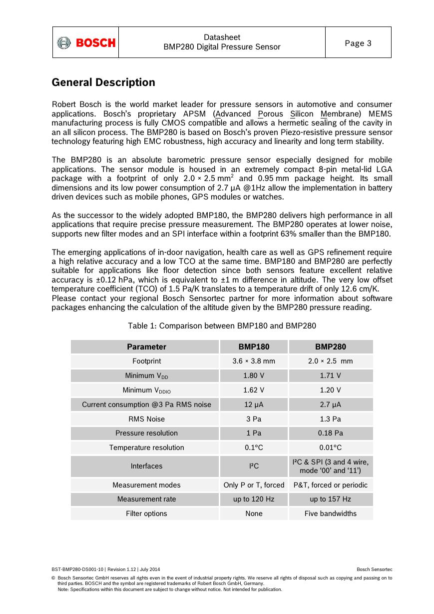
Table 1: Comparison between BMP180 and BMP280
Parameter
Footprint
Minimum VDD
Minimum VDDIO
Current consumption @3 Pa RMS noise
RMS Noise
Pressure resolution
Temperature resolution
Interfaces
BMP180
BMP280
3.6 × 3.8 mm
2.0 × 2.5 mm
1.80 V
1.62 V
12 µA
3 Pa
1 Pa
0.1°C
I²C
1.71 V
1.20 V
2.7 µA
1.3 Pa
0.18 Pa
0.01°C
I²C & SPI (3 and 4 wire,
mode ‘00’ and ‘11’)
Measurement modes
Only P or T, forced P&T, forced or periodic
Measurement rate
up to 120 Hz
up to 157 Hz
Filter options
None
Five bandwidths
BST-BMP280-DS001-10 | Revision 1.12 | July 2014
Bosch Sensortec
© Bosch Sensortec GmbH reserves all rights even in the event of industrial property rights. We reserve all rights of disposal such as copying and passing on to
third parties. BOSCH and the symbol are registered trademarks of Robert Bosch GmbH, Germany.
Note: Specifications within this document are subject to change without notice. Not intended for publication.
�
Datasheet
BMP280 Digital Pressure Sensor
Page 4
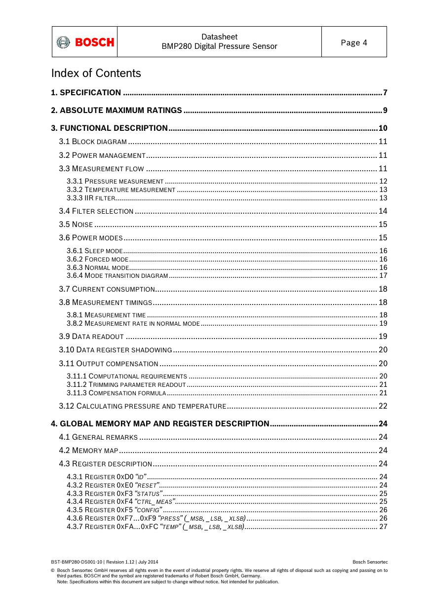
Index of Contents
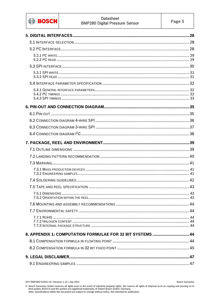
1. SPECIFICATION ........................................................................................................................ 7
2. ABSOLUTE MAXIMUM RATINGS ............................................................................................ 9
3. FUNCTIONAL DESCRIPTION ................................................................................................. 10
3.1 BLOCK DIAGRAM ............................................................................................................... 11
3.2 POWER MANAGEMENT ....................................................................................................... 11
3.3 MEASUREMENT FLOW ....................................................................................................... 11
3.3.1 PRESSURE MEASUREMENT ........................................................................................................... 12
3.3.2 TEMPERATURE MEASUREMENT ..................................................................................................... 13
3.3.3 IIR FILTER .................................................................................................................................... 13
3.4 FILTER SELECTION ............................................................................................................ 14
3.5 NOISE .............................................................................................................................. 15
3.6 POWER MODES ................................................................................................................. 15
3.6.1 SLEEP MODE ................................................................................................................................ 16
3.6.2 FORCED MODE ............................................................................................................................. 16
3.6.3 NORMAL MODE ............................................................................................................................. 16
3.6.4 MODE TRANSITION DIAGRAM ......................................................................................................... 17
3.7 CURRENT CONSUMPTION................................................................................................... 18
3.8 MEASUREMENT TIMINGS .................................................................................................... 18
3.8.1 MEASUREMENT TIME .................................................................................................................... 18
3.8.2 MEASUREMENT RATE IN NORMAL MODE ......................................................................................... 19
3.9 DATA READOUT ................................................................................................................ 19
3.10 DATA REGISTER SHADOWING ........................................................................................... 20
3.11 OUTPUT COMPENSATION ................................................................................................. 20
3.11.1 COMPUTATIONAL REQUIREMENTS ............................................................................................... 20
3.11.2 TRIMMING PARAMETER READOUT ................................................................................................ 21
3.11.3 COMPENSATION FORMULA .......................................................................................................... 21
3.12 CALCULATING PRESSURE AND TEMPERATURE ................................................................... 22
4. GLOBAL MEMORY MAP AND REGISTER DESCRIPTION .................................................. 24
4.1 GENERAL REMARKS .......................................................................................................... 24
4.2 MEMORY MAP ................................................................................................................... 24
4.3 REGISTER DESCRIPTION .................................................................................................... 24
4.3.1 REGISTER 0XD0 “ID” .................................................................................................................... 24
4.3.2 REGISTER 0XE0 “RESET” .............................................................................................................. 24
4.3.3 REGISTER 0XF3 “STATUS” ............................................................................................................ 25
4.3.4 REGISTER 0XF4 “CTRL_MEAS” ...................................................................................................... 25
4.3.5 REGISTER 0XF5 “CONFIG” ............................................................................................................ 26
4.3.6 REGISTER 0XF7…0XF9 “PRESS” (_MSB, _LSB, _XLSB) .................................................................. 26
4.3.7 REGISTER 0XFA…0XFC “TEMP” (_MSB, _LSB, _XLSB)................................................................... 27
BST-BMP280-DS001-10 | Revision 1.12 | July 2014
Bosch Sensortec
© Bosch Sensortec GmbH reserves all rights even in the event of industrial property rights. We reserve all rights of disposal such as copying and passing on to
third parties. BOSCH and the symbol are registered trademarks of Robert Bosch GmbH, Germany.
Note: Specifications within this document are subject to change without notice. Not intended for publication.
�
Datasheet
BMP280 Digital Pressure Sensor
Page 5
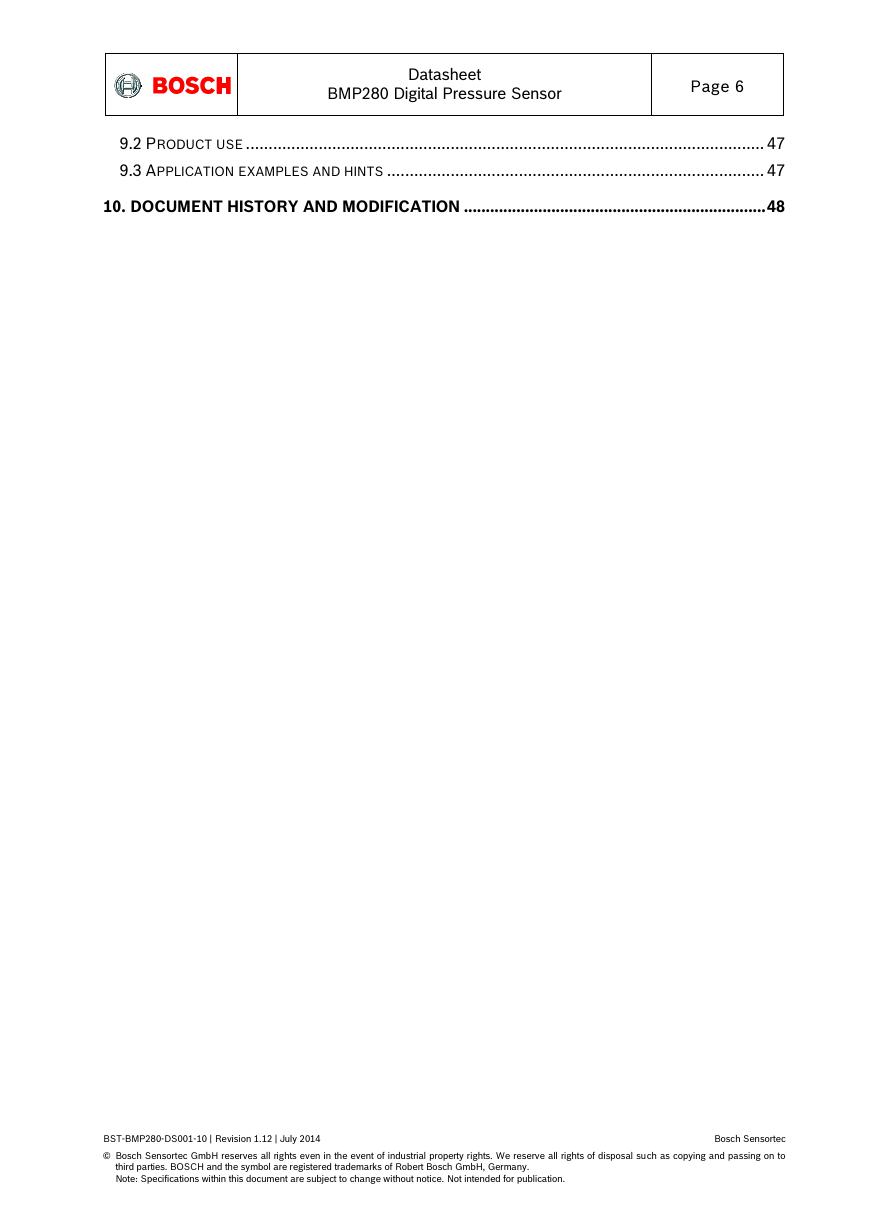
5. DIGITAL INTERFACES ............................................................................................................ 28
5.1 INTERFACE SELECTION ...................................................................................................... 28
5.2 I²C INTERFACE.................................................................................................................. 28
5.2.1 I²C WRITE .................................................................................................................................... 29
5.2.2 I²C READ ..................................................................................................................................... 29
5.3 SPI INTERFACE ................................................................................................................. 30
5.3.1 SPI WRITE ................................................................................................................................... 31
5.3.2 SPI READ .................................................................................................................................... 31
5.4 INTERFACE PARAMETER SPECIFICATION ............................................................................. 32
5.4.1 GENERAL INTERFACE PARAMETERS ............................................................................................... 32
5.4.2 I²C TIMINGS ................................................................................................................................. 32
5.4.3 SPI TIMINGS ................................................................................................................................ 33
6. PIN-OUT AND CONNECTION DIAGRAM ............................................................................... 35
6.1 PIN-OUT ........................................................................................................................... 35
6.2 CONNECTION DIAGRAM 4-WIRE SPI ................................................................................... 36
6.3 CONNECTION DIAGRAM 3-WIRE SPI ................................................................................... 37
6.4 CONNECTION DIAGRAM I2C ................................................................................................ 38
7. PACKAGE, REEL AND ENVIRONMENT ................................................................................ 39
7.1 OUTLINE DIMENSIONS ....................................................................................................... 39
7.2 LANDING PATTERN RECOMMENDATION ............................................................................... 40
7.3 MARKING .......................................................................................................................... 41
7.3.1 MASS PRODUCTION DEVICES ........................................................................................................ 41
7.3.2 ENGINEERING SAMPLES ................................................................................................................ 41
7.4 SOLDERING GUIDELINES .................................................................................................... 42
7.5 TAPE AND REEL SPECIFICATION ......................................................................................... 43
7.5.1 DIMENSIONS ................................................................................................................................ 43
7.5.2 ORIENTATION WITHIN THE REEL ..................................................................................................... 43
7.6 MOUNTING AND ASSEMBLY RECOMMENDATIONS ................................................................. 44
7.7 ENVIRONMENTAL SAFETY .................................................................................................. 44
7.7.1 ROHS ......................................................................................................................................... 44
7.7.2 HALOGEN CONTENT ..................................................................................................................... 44
7.7.3 INTERNAL PACKAGE STRUCTURE ................................................................................................... 44
8. APPENDIX 1: COMPUTATION FORMULAE FOR 32 BIT SYSTEMS .................................. 44
8.1 COMPENSATION FORMULA IN FLOATING POINT .................................................................... 44
8.2 COMPENSATION FORMULA IN 32 BIT FIXED POINT ................................................................ 45
9. LEGAL DISCLAIMER ............................................................................................................... 47
9.1 ENGINEERING SAMPLES .................................................................................................... 47
BST-BMP280-DS001-10 | Revision 1.12 | July 2014
Bosch Sensortec
© Bosch Sensortec GmbH reserves all rights even in the event of industrial property rights. We reserve all rights of disposal such as copying and passing on to
third parties. BOSCH and the symbol are registered trademarks of Robert Bosch GmbH, Germany.
Note: Specifications within this document are subject to change without notice. Not intended for publication.
�
Datasheet
BMP280 Digital Pressure Sensor
Page 6
9.2 PRODUCT USE .................................................................................................................. 47
9.3 APPLICATION EXAMPLES AND HINTS ................................................................................... 47
10. DOCUMENT HISTORY AND MODIFICATION ..................................................................... 48
BST-BMP280-DS001-10 | Revision 1.12 | July 2014
Bosch Sensortec
© Bosch Sensortec GmbH reserves all rights even in the event of industrial property rights. We reserve all rights of disposal such as copying and passing on to
third parties. BOSCH and the symbol are registered trademarks of Robert Bosch GmbH, Germany.
Note: Specifications within this document are subject to change without notice. Not intended for publication.
�
Datasheet
BMP280 Digital Pressure Sensor
Page 7
1. Specification
If not stated otherwise,
All values are valid over the full voltage range
All minimum/maximum values are given for the full accuracy temperature range
Minimum/maximum values of drifts, offsets and temperature coefficients are ±3 values
over lifetime
Typical values of currents and state machine timings are determined at 25 °C
Minimum/maximum values of currents are determined using corner lots over complete
temperature range
Minimum/maximum values of state machine timings are determined using corner lots
over 0…+65 °C temperature range
The specification tables are split into pressure and temperature part of BMP280
Table 2: Parameter specification
Parameter
Symbol
Condition
operational
full accuracy
Min
-40
0
full accuracy
300
Operating temperature
range
Operating pressure
range
TA
P
Sensor supply voltage
VDD
ripple max. 50mVpp
1.71
Interface supply voltage
VDDIO
1.2
Supply current
IDD,LP
Peak current
Current at temperature
measurement
Ipeak
IDDT
1 Hz forced mode,
pressure and
temperature, lowest
power
during pressure
measurement
Sleep current1
IDDSL
25 °C
Standby current
(inactive period of
normal mode) 2
Relative accuracy
pressure3
VDD = 3.3V
IDDSB
25 °C
Arel
700 … 900hPa
25 . . . 40 °C
1 Typical value at VDD = VDDIO = 1.8 V, maximal value at VDD = VDDIO = 3.6 V.
2 Typical value at VDD = VDDIO = 1.8 V, maximal value at VDD = VDDIO = 3.6 V.
3 Target values
Typ
Max
Units
25
1.8
1.8
+85
+65
°C
1100
hPa
3.6
3.6
V
V
2.8
4.2
µA
720
1120
µA
325
µA
0.1
0.3
µA
0.2
0.5
µA
±0.12
±1.0
hPa
m
BST-BMP280-DS001-10 | Revision 1.12 | July 2014
Bosch Sensortec
© Bosch Sensortec GmbH reserves all rights even in the event of industrial property rights. We reserve all rights of disposal such as copying and passing on to
third parties. BOSCH and the symbol are registered trademarks of Robert Bosch GmbH, Germany.
Note: Specifications within this document are subject to change without notice. Not intended for publication.
�
Datasheet
BMP280 Digital Pressure Sensor
Page 8
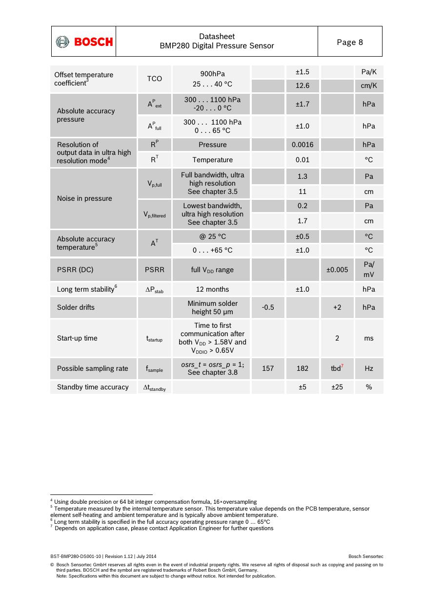
Offset temperature
coefficient3
Absolute accuracy
pressure
Resolution of
output data in ultra high
resolution mode4
Noise in pressure
TCO
AP
ext
AP
full
RP
RT
Vp,full
Vp,filtered
Absolute accuracy
temperature5
AT
900hPa
25 . . . 40 °C
300 . . . 1100 hPa
-20 . . . 0 °C
300 . . . 1100 hPa
0 . . . 65 °C
Pressure
Temperature
Full bandwidth, ultra
high resolution
See chapter 3.5
Lowest bandwidth,
ultra high resolution
See chapter 3.5
@ 25 °C
0 . . . +65 °C
PSRR (DC)
PSRR
full VDD range
Long term stability6
Pstab
12 months
±1.5
12.6
±1.7
±1.0
0.0016
0.01
1.3
11
0.2
1.7
±0.5
±1.0
±0.005
±1.0
Pa/K
cm/K
hPa
hPa
hPa
°C
Pa
cm
Pa
cm
°C
°C
Pa/
mV
hPa
Solder drifts
Start-up time
tstartup
Possible sampling rate
fsample
Minimum solder
height 50 µm
Time to first
communication after
both VDD > 1.58V and
VDDIO > 0.65V
osrs_t = osrs_p = 1;
See chapter 3.8
-0.5
+2
hPa
2
ms
157
182
tbd7
Hz
Standby time accuracy
tstandby
±5
±25
%
4 Using double precision or 64 bit integer compensation formula, 16×oversampling
5 Temperature measured by the internal temperature sensor. This temperature value depends on the PCB temperature, sensor
element self-heating and ambient temperature and is typically above ambient temperature.
6 Long term stability is specified in the full accuracy operating pressure range 0 … 65°C
7 Depends on application case, please contact Application Engineer for further questions
BST-BMP280-DS001-10 | Revision 1.12 | July 2014
Bosch Sensortec
© Bosch Sensortec GmbH reserves all rights even in the event of industrial property rights. We reserve all rights of disposal such as copying and passing on to
third parties. BOSCH and the symbol are registered trademarks of Robert Bosch GmbH, Germany.
Note: Specifications within this document are subject to change without notice. Not intended for publication.
�



 V2版本原理图(Capacitive-Fingerprint-Reader-Schematic_V2).pdf
 摄像头工作原理.doc
 VL53L0X简要说明(En.FLVL53L00216).pdf
 原理图(DVK720-Schematic).pdf
 原理图(Pico-Clock-Green-Schdoc).pdf
 原理图(RS485-CAN-HAT-B-schematic).pdf
 File:SIM7500_SIM7600_SIM7800 Series_SSL_Application Note_V2.00.pdf
 ADS1263(Ads1262).pdf
 原理图(Open429Z-D-Schematic).pdf
 用户手册(Capacitive_Fingerprint_Reader_User_Manual_CN).pdf
 CY7C68013A(英文版)(CY7C68013A).pdf
 TechnicalReference_Dem.pdf