Core1081
Data Sheet
Embedded Wi-Fi module
2.2
Date:2014-02-13
Data Sheet
Overview
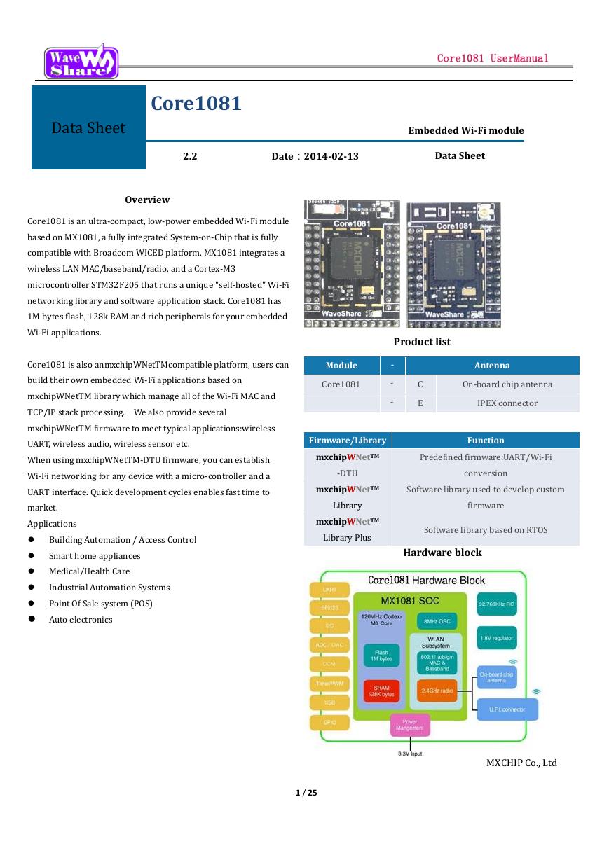
Core1081 is an ultra-compact, low-power embedded Wi-Fi module
based on MX1081, a fully integrated System-on-Chip that is fully
compatible with Broadcom WICED platform. MX1081 integrates a
wireless LAN MAC/baseband/radio, and a Cortex-M3
microcontroller STM32F205 that runs a unique "self-hosted" Wi-Fi
networking library and software application stack. Core1081 has
1M bytes flash, 128k RAM and rich peripherals for your embedded
Wi-Fi applications.
Core1081 is also anmxchipWNetTMcompatible platform, users can
build their own embedded Wi-Fi applications based on
mxchipWNetTM library which manage all of the Wi-Fi MAC and
TCP/IP stack processing. We also provide several
mxchipWNetTM firmware to meet typical applications:wireless
UART, wireless audio, wireless sensor etc.
When using mxchipWNetTM-DTU firmware, you can establish
Wi-Fi networking for any device with a micro-controller and a
UART interface. Quick development cycles enables fast time to
market.
Applications
Building Automation / Access Control
Smart home appliances
Medical/Health Care
Industrial Automation Systems
Point Of Sale system (POS)
Auto electronics
Product list
Module
Core1081
-
-
-
Antenna
C
E
On-board chip antenna
IPEX connector
Firmware/Library
Function
mxchipWNetTM
Predefined firmware:UART/Wi-Fi
-DTU
conversion
mxchipWNetTM
Software library used to develop custom
Library
mxchipWNetTM
Library Plus
firmware
Software library based on RTOS
Hardware block
1 / 25
MXCHIP Co., Ltd
�
contents
1.
2.
Introduction .................................................................................................................................................................... 3
Interface .......................................................................................................................................................................... 5
2.1. Pinouts .................................................................................................................................................................. 5
2.2. Pin Arrangement ................................................................................................................................................... 6
2.3. Pin Arrangement for peripherals ........................................................................................................................ 10
3. Electrical Parameters ................................................................................................................................................... 12
3.1. Absolute maximum ratings: ................................................................................................................................ 12
3.1.1. Voltage & Current................................................................................................................................................................................................... 12
3.2. Operating conditions .......................................................................................................................................... 12
3.2.1. Voltage & Current................................................................................................................................................................................................... 12
3.3. Digital I/O port characteristics ............................................................................................................................ 15
3.3.1. Output voltage levels ............................................................................................................................................................................................. 15
3.3.2. Output voltage levels ............................................................................................................................................................................................. 16
3.3.3. nRESET pin characteristics ................................................................................................................................................................................... 16
3.4. Other MCU electrical parameters ...................................................................................................................... 16
3.5. Temperature andHumidity ................................................................................................................................. 16
3.6. ESD ...................................................................................................................................................................... 17
3.7.
Static latch-up ..................................................................................................................................................... 17
3.8. RF characteristics ................................................................................................................................................ 17
3.8.1. Basic RF characteristics......................................................................................................................................................................................... 17
3.8.2. IEEE802.11bmode ................................................................................................................................................................................................. 18
3.8.3. IEEE802.11gmode ................................................................................................................................................................................................. 18
3.8.4. IEEE802.11n 20MHz bandwidth mode ............................................................................................................................................................... 20
3.9. Mechanical Dimensions ...................................................................................................................................... 22
3.9.1. Core1081 Mechanical Dimensions ....................................................................................................................................................................... 22
4. Minimizing radio interference .................................................................................................................................... 23
4.1. U.F.L RF Connector .............................................................................................................................................. 23
5. U.F.L RF Connector ....................................................................................................................................................... 24
5.1. Recommended Reflow Profile ............................................................................................................................ 24
5.2. MSL/Storage Condition ....................................................................................................................................... 25
2 / 25
�
1. Introduction
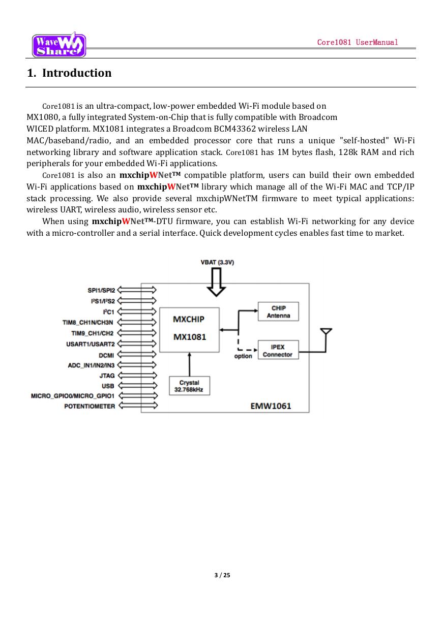
Core1081 is an ultra-compact, low-power embedded Wi-Fi module based on
MX1080, a fully integrated System-on-Chip that is fully compatible with Broadcom
WICED platform. MX1081 integrates a Broadcom BCM43362 wireless LAN
MAC/baseband/radio, and an embedded processor core that runs a unique "self-hosted" Wi-Fi
networking library and software application stack. Core1081 has 1M bytes flash, 128k RAM and rich
peripherals for your embedded Wi-Fi applications.
Core1081 is also an mxchipWNetTM compatible platform, users can build their own embedded
Wi-Fi applications based on mxchipWNetTM library which manage all of the Wi-Fi MAC and TCP/IP
stack processing. We also provide several mxchipWNetTM firmware to meet typical applications:
wireless UART, wireless audio, wireless sensor etc.
When using mxchipWNetTM-DTU firmware, you can establish Wi-Fi networking for any device
with a micro-controller and a serial interface. Quick development cycles enables fast time to market.
3 / 25
�
1.1. Features
Single operation voltage:3.3V
Power consumption:
Only ~7mA while module is connected to access point and no data is transmitting,
Only ~24mA while sending data under 20kbps,
Only 8μA under standby mode.
STM32F2 MCU frequency: 120MHz,flash size: 1M bytes,RAM size: 128k bytes.
On-chip functionality Single-chip: MAC/BB/RF
Peripherals:
42 x GPIOs
3 x UARTs,UART2 include hardware flow control
2 x SPI, 1xIIS
8 x ADC input channels,2 DAC output channel
1 x USB device, 1 x CAN
2 x I2C
PWM/Timer input/output
DCMI
SWD debug interface
Wi-Fi connectivity
802.11b, 802.11g, 802.11n (single stream) on channel 1-14@2.4GHz
WEP, WPA/WPA2 PSK/Enterprise
Transmit power:18.5dBm@11b,15.5dBm@11g,14.5dBm@11n
MIN Receiver Sensitivity: -96 dBm
Max Data rate:11Mbps@11b,54Mbps@11g,72Mbps@11n HT20
Wi-Fi modes:Station, Soft AP and Wi-Fi direct
Advanced 1x1 802.11n features
Full/Half Guard Interval
Frame Aggregation
Space Time Block Coding (STBC)
Low Density Parity Check (LDPC) Encoding
Hardware Encryption: WEP, WPA/WPA2
WPS 2.0
Multiple power save modes
On-board chip antenna,IPEX connector for external antenna
CE,FCC compliant
Operating Temperature: -40℃ to 85℃
MSL level 3
4 / 25
�
2. Interface
2.1. Pinouts
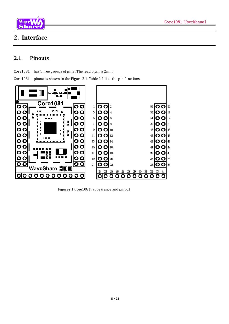
Core1081 has Three groups of pins . The lead pitch is 2mm.
Core1081 pinout is shown in the Figure 2.1. Table 2.2 lists the pin functions.
Figure2.1 Core1081: appearance and pinout
5 / 25
�
2.2. Pin Arrangement
Figure 2.2 Core1081 pin arrangement
Pins
Number
Pin Name Type
IO
Main function
level
(after reset)
1
PA6
I/O
FT
PA6
2
PA7
I/O
FT
PA7
3
PB15
I/O
FT
PB15
4
PB14
I/O
FT
PB14
5
PB12
I/O
FT
PB12
PH8
I/O
FT
PH9
I/O
FT
PH8
PH9
PH10
I/O
FT
PH10
PH11
I/O
FT
PH11
6
7
8
9
Alternate functions
Other functions
SPI1_MISO /
TIM8_BKIN/TIM13_CH1 /
DCMI_PIXCLK / TIM3_CH1
/ TIM1_BKIN/ EVENTOUT
SPI1_MOSI/ TIM8_CH1N /
TIM14_CH1
TIM3_CH2/
ETH_MII_RX_DV /
TIM1_CH1N /
RMII_CRS_DV /
EVENTOUT
SPI2_MOSI / I2S2_SD /
TIM1_CH3N / TIM8_CH3N
/ TIM12_CH2 /
OTG_HS_DP / RTC_50Hz/
EVENTOUT
SPI2_MISO/ TIM1_CH2N /
TIM12_CH1 / OTG_HS_DM
USART3_RTS/
TIM8_CH2N/ EVENTOUT
SPI2_NSS/I2S2_WS/
I2C2_SMBA/
USART3_CK/ TIM1_BKIN /
CAN2_RX /
OTG_HS_ULPI_D5/
ETH_RMII_TXD0 /
ETH_MII_TXD0/
OTG_HS_ID/ EVENTOUT
I2C3_SDA / DCMI_HSYNC/
EVENTOUT
I2C3_SMBA / TIM12_CH2/
DCMI_D0/ EVENTOUT
TIM5_CH1 / DCMI_D1/
EVENTOUT
TIM5_CH2 / DCMI_D2/
EVENTOUT
6 / 25
ADC12_IN6
ADC12_IN7
�
Pins
Number
Pin Name Type
IO
Main function
level
(after reset)
10
11
PH12
I/O
FT
PH12
PH14
I/O
FT
PH14
12
PA9
I/O
FT
PA9
13
PA10
I/O
FT
PA10
14
15
16
17
18
19
20
PD0
I/O
FT
PD1
I/O
FT
PD5
I/O
FT
PD6
PA13
PA14
I/O
I/O
I/O
FT
FT
FT
PD0
PD1
PD5
PD6
PA13
PA14
PA15
I/O
FT
PA15
21
PB3
I/O
FT
PB3
22
23
24
25
26
27
PB4
I/O
FT
PB4
GND
3.3V
GND
3.3V
PH13
I/O
FT
PH13
PH15
I/O
FT
PH15
PI2
I/O
FT
PI2
28
PI0
I/O
FT
PI0
Alternate functions
Other functions
TIM5_CH3 / DCMI_D3/
EVENTOUT
TIM8_CH2N / DCMI_D4/
EVENTOUT
USART1_TX/ TIM1_CH2 /
I2C3_SMBA / DCMI_D0/
EVENTOUT
USART1_RX/ TIM1_CH3/
OTG_FS_ID/DCMI_D1/
EVENTOUT
FSMC_D2/CAN1_RX/
EVENTOUT
FSMC_D3 / CAN1_TX/
EVENTOUT
FSMC_NWE/USART2_TX/
EVENTOUT
FSMC_NWAIT/
USART2_RX/ EVENTOUT
JTMS-SWDIO/ EVENTOUT
JTCK-SWCLK/ EVENTOUT
JTDI/ SPI3_NSS/
I2S3_WS/TIM2_CH1_ETR
/ SPI1_NSS/ EVENTOUT
JTDO/ TRACESWO/
SPI3_SCK / I2S3_SCK /
TIM2_CH2 / SPI1_SCK/
EVENTOUT
NJTRST/ SPI3_MISO /
TIM3_CH1 / SPI1_MISO/
EVENTOUT
TIM8_CH1N / CAN1_TX/
EVENTOUT
TIM8_CH3N / DCMI_D11/
EVENTOUT
TIM8_CH4 /SPI2_MISO /
DCMI_D9/ EVENTOUT
TIM5_CH4 / SPI2_NSS /
I2S2_WS / DCMI_D13/
EVENTOUT
OTG_FS_
VBUS
7 / 25
�
Pins
Number
Pin Name Type
IO
Main function
level
(after reset)
Alternate functions
Other functions
29
PB7
I/O
FT
PB7
30
PB6
I/O
FT
PB6
31
PC6
I/O
FT
PC6
32
33
34
35
36
37
38
3.3V
GND
PI1
BOOT0
PI6
I/O
I/O
I/O
FT
FT
PI4
I/O
FT
3.3V
GND
PI1
BOOT0
PI6
PI4
39
PI3
I/O
FT
PI3
40
PI5
I/O
FT
PI5
41
PI7
I/O
FT
PI7
42
PE5
I/O
FT
PE5
43
PE6
I/O
FT
PE6
44
PF9
I/O
FT
PF9
I2C1_SDA / FSMC_NL(8)/
DCMI_VSYNC /
USART1_RX/ TIM4_CH2/
EVENTOUT
I2C1_SCL/ TIM4_CH1 /
CAN2_TX /
DCMI_D5/USART1_TX/
EVENTOUT
I2S2_MCK /
TIM8_CH1/SDIO_D6 /
USART6_TX /
DCMI_D0/TIM3_CH1/
EVENTOUT
SPI2_SCK / I2S2_SCK /
DCMI_D8/ EVENTOUT
TIM8_CH2 / DCMI_D6/
EVENTOUT
TIM8_BKIN / DCMI_D5/
EVENTOUT
TIM8_ETR / SPI2_MOSI /
I2S2_SD / DCMI_D10/
EVENTOUT
TIM8_CH1 /
DCMI_VSYNC/
EVENTOUT
TIM8_CH3 / DCMI_D7/
EVENTOUT
TRACED2 / FSMC_A21 /
TIM9_CH1 / DCMI_D6/
EVENTOUT
TRACED3 / FSMC_A22 /
TIM9_CH2 / DCMI_D7/
EVENTOUT
TIM14_CH1 / FSMC_CD/
EVENTOUT
8 / 25
ADC3_IN7
�


 V2版本原理图(Capacitive-Fingerprint-Reader-Schematic_V2).pdf
 摄像头工作原理.doc
 VL53L0X简要说明(En.FLVL53L00216).pdf
 原理图(DVK720-Schematic).pdf
 原理图(Pico-Clock-Green-Schdoc).pdf
 原理图(RS485-CAN-HAT-B-schematic).pdf
 File:SIM7500_SIM7600_SIM7800 Series_SSL_Application Note_V2.00.pdf
 ADS1263(Ads1262).pdf
 原理图(Open429Z-D-Schematic).pdf
 用户手册(Capacitive_Fingerprint_Reader_User_Manual_CN).pdf
 CY7C68013A(英文版)(CY7C68013A).pdf
 TechnicalReference_Dem.pdf