WiFi MCU Module Specification
Nov.2012
WiFi MCU Module
Embedded Wireless LAN Controller SIP Module
The Specification maybe changed.
.
1
�
REVISION HISTORY
Version No. Revised Date Revised by
Description
Notes
1.0
2012-03-28
Ken
Preliminary specification released
Proposal
1.1
2012-04-09
James
1. Add Revision History information
2. Modify Pin Description of the Pin24,
Proposal
1.2
2012-04-20
James
1.3
2012-06-27
James
1.4
2012-07-19
James
1.5
2012-08-08
James
Pin25, &Pin26
1. Update Block diagram (add DCMI
Interface)
2. Modify Pin Out Counts (change
from 51 to 58), Pin Description
3. Add DCMI Interface Characteristics
4. Modify Mechanical Dimension
1. Update Block Diagram
2. Update Pin out counts & Pin
Description
3. Update Mechanical Dimension
1. Update Block Diagram (add Timer
Function)
2. Update Pin out counts & Pin
Description
3. Add TIM timer Interface
Characteristics
4. Add pin definition Mapping to
STM32F20x LQFP176 information.
1. Update Block Diagram (add
I2S/USB, Potentiometer Function)
2. Update Pin out counts & Pin
Description
3. Add I2S Interface Characteristics
4. Modify Mechanical Dimension
5. Update Module Recommend
Footprint & Stencil information
Proposal
Proposal
Proposal
Proposal
1.6
2012-08-14
James
1. Update Module Recommend
Footprint & Stencil information
Proposal
1.7
2012-11-05
James
Recommend Stencil
Proposal
1. Modify the Recommend footprint &
1.8
2012-11-23
James
2. Add Alternate function mapping Table
1. Modify current Consumption data of TX
mode & RX mode.
Proposal
The Specification maybe changed.
.
2
�
TABLE OF CONTENTS
7.3 Mechanical Dimension ................................... 29
8. Recommend Footprint ..................... 30
9. Recommend Stencil ......................... 31
10. Recommended Reflow Profile ....... 32
11. Package and Storage Condition .... 32
11.1 Package Dimension ..................................... 32
11.2 Laser Mark ................................................... 33
11.3 Pin 1 Location in the Tape/Reel ................... 33
11.4 Ordering Information .................................... 33
11.5 MSL & Moisture Sensitive LEVEL ................ 34
12. Application Reference Design ....... 35
Revision History ........................................... 2
1.
Introduction ........................................ 4
1.1
1.2
Description ................................................ 4
Features .................................................... 5
2. Block Diagram .................................... 6
3. Electrical Specification ...................... 7
3.1 Absolute Maximum Rating ............................... 7
3.2 Recommendable Operation Condition ............. 7
3.2.1 Temperature, Humidity ............................. 7
3.2.2 Voltage ...................................................... 8
3.3 Current Consumption ....................................... 8
3.3.1 WLAN ....................................................... 8
4. RF Specification ................................. 9
4.1 wireless Specification ....................................... 9
4.2 WiFi RF Transmitter Specification ................. 10
4.3 WIFi RF Receiver Specification ..................... 12
5. Pin Definition .................................... 14
5.1 The detail pin definition information ............... 14
5.2 Alternate function mapping Table ......... 18
6. Addition Information ........................ 21
6.1 Low Speed External Clock Source
Characteristics ..................................................... 21
6.2 Communications Interfaces ........................... 23
6.2.1 I2C Interface Characteristics....................... 23
6.2.2 SPI Interface Characteristics ...................... 25
6.2.3 DCMI Interface Characteristics ................... 25
6.2.4 TIM timer Interface Characteristics ............. 26
6.2.5 I2S timer Interface Characteristics .............. 27
6.2.5 USB HS characteristics ............................... 28
7. Mechanical & Weight Specification 29
7.1 Size of the Module ......................................... 29
7.2 Weight of the Module ..................................... 29
The Specification maybe changed.
.
3
�
1. Introduction
1.1 Description
This is a complete WiFi MCU module which is designed for embedded wireless solution and a
cost-effective, low power capabilities high performance MCU in M2M applications. It includes
standards-based wired and wireless technologies to enable IP infrastructures for smart grid, smart
home, security, building automation, toys, robots, remote health and wellness monitoring and other
M2M applications.
The module integrates ARM CortexTM-M3 MCU, clock, WIFi and front end into a smallest form
factor LGA package. It is based on Broadcom IEEE802.11 b/g/n antenna diversity single-stream
Broadcom align technology. Thus, it can be used to enable wireless connectivity to the simplest
existing sensor products with minimal engineering effort.
The solution is provided as a module to reduce development time, lower manufacturing costs, save
board space, ease certification, and minimize RF expertise required. Additionally it is provided as a
complete platform solution including software drivers, sample applications, API guide, user
documentation and a world-class support community.
The Specification maybe changed.
.
4
�
1.2
Features
MCU STM32 ARM 32-bit CortexTM-M3 Frequency up to 120 MHz
Diverse serial interface SPI, USART
Sensor applications support ADC, I2C, I2S,GPIO, CAN bus, 8-bit parallel camera interface,
Timers,USB
Debug interface support JTAG
On-chip functionality Single-chip MAC/BB/RF
Frequency Band 2.4 GHz
Transmit Power +17 dBm @b mode/11 Mbps
MIN Receiver Sensitivity -96 dBm
Network Standard 802.11b, 802.11g, 802.11n (single stream)
Modulation Modes CCK and OFDM with BPSK, QPSK, 16 QAM, 64QAM
Hardware Encryption WEP, WPA/WPA2
Supported Data Rates IEEE 802.11b 1 – 11 Mbps
IEEE 802.11g 6 – 54 Mbps
Advanced 1x1 802.11n features Full/Half Guard Interval
IEEE 802.11n (2.4 GHz) 7.2 – 72.2 Mbps
Frame Aggregation
Space Time Block Coding (STBC)
Low Density Parity Check (LDPC) Encoding
Two antenna configurations Supported antenna diversity
Operating Temperature -40℃ to 85℃
MSL level 3
Certification FCC and CE compliant
The Specification maybe changed.
.
5
�
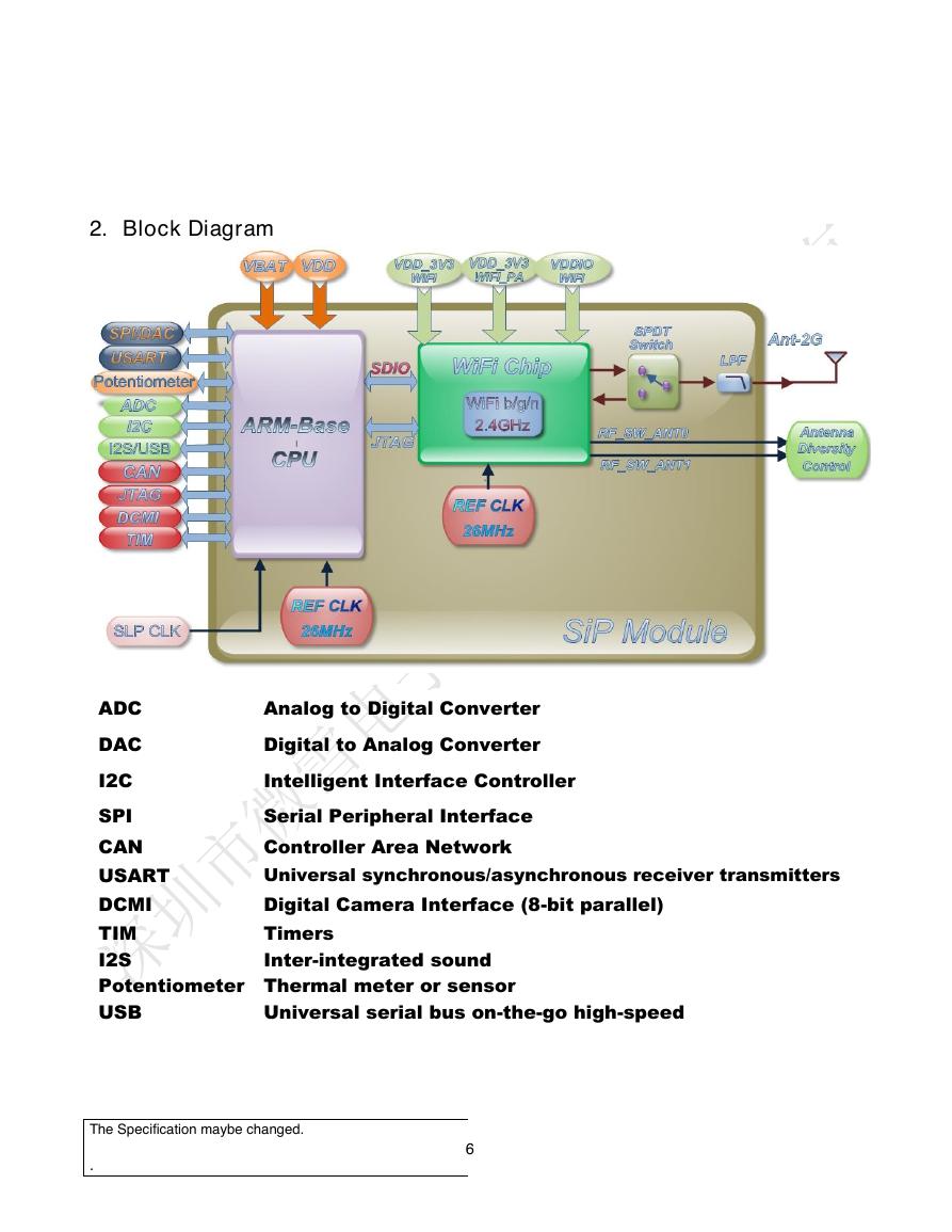
2. Block Diagram
ADC
DAC
I2C
SPI
CAN
USART
DCMI
TIM
I2S
Analog to Digital Converter
Digital to Analog Converter
Intelligent Interface Controller
Serial Peripheral Interface
Controller Area Network
Universal synchronous/asynchronous receiver transmitters
Digital Camera Interface (8-bit parallel)
Timers
Inter-integrated sound
Potentiometer Thermal meter or sensor
USB
Universal serial bus on-the-go high-speed
The Specification maybe changed.
.
6
�
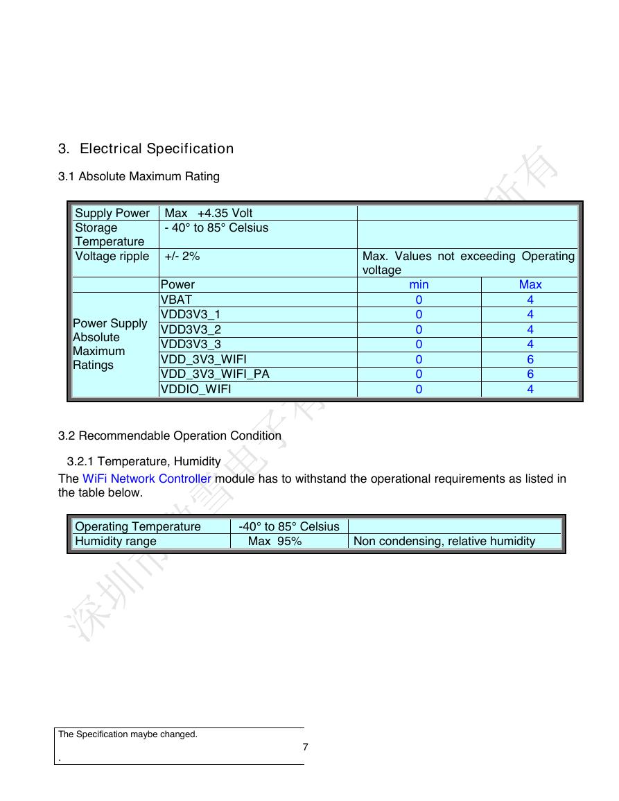
3. Electrical Specification
3.1 Absolute Maximum Rating
Supply Power Max +4.35 Volt
Storage
Temperature
Voltage ripple +/- 2%
- 40° to 85° Celsius
Power Supply
Absolute
Maximum
Ratings
Power
VBAT
VDD3V3_1
VDD3V3_2
VDD3V3_3
VDD_3V3_WIFI
VDD_3V3_WIFI_PA
VDDIO_WIFI
3.2 Recommendable Operation Condition
3.2.1 Temperature, Humidity
Max. Values not exceeding Operating
voltage
min
Max
0
0
0
0
0
0
0
4
4
4
4
6
6
4
The WiFi Network Controller module has to withstand the operational requirements as listed in
the table below.
Operating Temperature
Humidity range
-40° to 85° Celsius
Max 95%
Non condensing, relative humidity
The Specification maybe changed.
.
7
�
3.2.2 Voltage
Power supply for the WiFi Network Controller module will be provided by the host via the power
pins
Parameter
MCU VBAT Voltage
GPIO I/O Supply
GPIO I/O Supply
GPIO I/O Supply
WiFi Voltage
WiFi PA Voltage
MCU With WiFi
Min
2.0
2.4
2.4
2.4
Only WiFi Function
1.8
Typ
3.3
3.3
3.3
3.3
3.3
3.3
3.3
3.3
Max
3.6
3.6
3.6
3.6
3.6
3.6
3.6
3.6
Unit
V
V
V
V
V
V
V
V
Symbol
VBAT
VDD3V3_1
VDD3V3_2
VDD3V3_3
VDD_3V3_WIFI
VDD_3V3_WIFI_PA
VDDIO_WIFI
3.3 Current Consumption
3.3.1 WLAN
Condition: Condition: 25deg.C, includes Both WiFi and Micro-Controller
Item
Condition
Min
Nom
Max
Unit
Tx mode(11b Max current)
Tx mode(11g Max current)
Tx mode(11n Max current)
Rx mode
11Mbps
54Mbps
MCS7
11b (11Mbps)
11g (54Mbps)
11n (MCS7)
345
250
210
115
115
115
150
150
150
mA
mA
mA
mA
mA
mA
The Specification maybe changed.
.
8
�




 V2版本原理图(Capacitive-Fingerprint-Reader-Schematic_V2).pdf
 摄像头工作原理.doc
 VL53L0X简要说明(En.FLVL53L00216).pdf
 原理图(DVK720-Schematic).pdf
 原理图(Pico-Clock-Green-Schdoc).pdf
 原理图(RS485-CAN-HAT-B-schematic).pdf
 File:SIM7500_SIM7600_SIM7800 Series_SSL_Application Note_V2.00.pdf
 ADS1263(Ads1262).pdf
 原理图(Open429Z-D-Schematic).pdf
 用户手册(Capacitive_Fingerprint_Reader_User_Manual_CN).pdf
 CY7C68013A(英文版)(CY7C68013A).pdf
 TechnicalReference_Dem.pdf