TFT LCD MODULE
0.96 inch 80RGB*160DOTS
MODULE NUMBER:
REVISION:
Customer:
Approved by
From:
Approved by
�
Contents
Revision History Contents
1. General Description
2. Mechanical Drawing
3. Pin Description
4. Electrical Characteristics
5. Optical characteristics
6. Reliability
7. Package Specifications
8.Precautions When Using These TFT Display
Modules
9. Warranty
10. Notice
�
1. General Description
1.1 Description
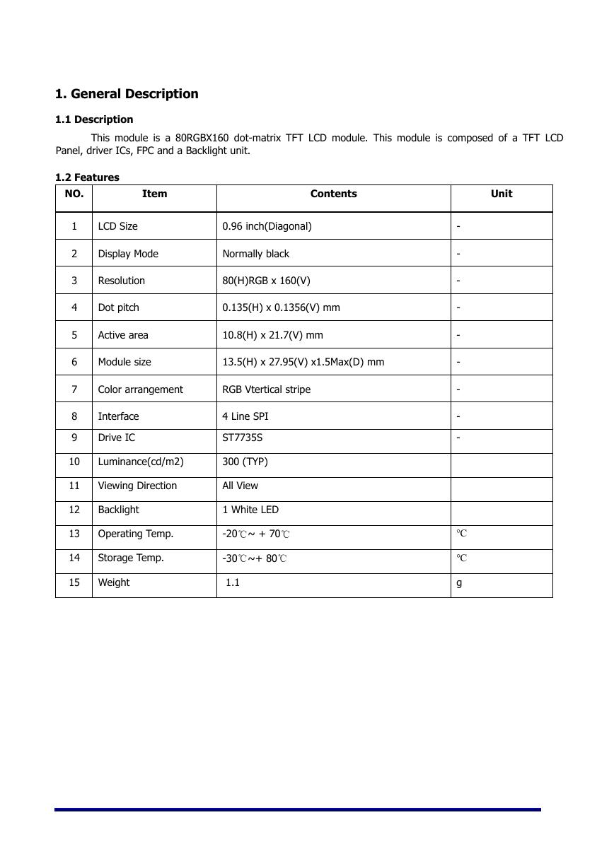
This module is a 80RGBX160 dot-matrix TFT LCD module. This module is composed of a TFT LCD
Panel, driver ICs, FPC and a Backlight unit.
1.2 Features
NO.
Item
Contents
Unit
1
2
3
4
5
6
7
8
9
10
11
12
13
14
Interface
Drive IC
Luminance(cd/m2)
Viewing Direction
Backlight
Operating Temp.
Storage Temp.
15 Weight
LCD Size
0.96 inch(Diagonal)
Display Mode
Normally black
Resolution
Dot pitch
Active area
Module size
80(H)RGB x 160(V)
0.135(H) x 0.1356(V) mm
10.8(H) x 21.7(V) mm
13.5(H) x 27.95(V) x1.5Max(D) mm
Color arrangement
RGB Vtertical stripe
4 Line SPI
ST7735S
300 (TYP)
All View
1 White LED
-20℃~ + 70℃
-30℃~+ 80℃
1.1
-
-
-
-
-
-
-
-
-
℃
℃
g
�
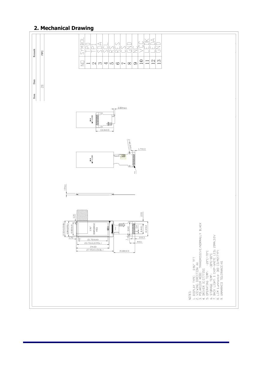
2. Mechanical Drawing
�
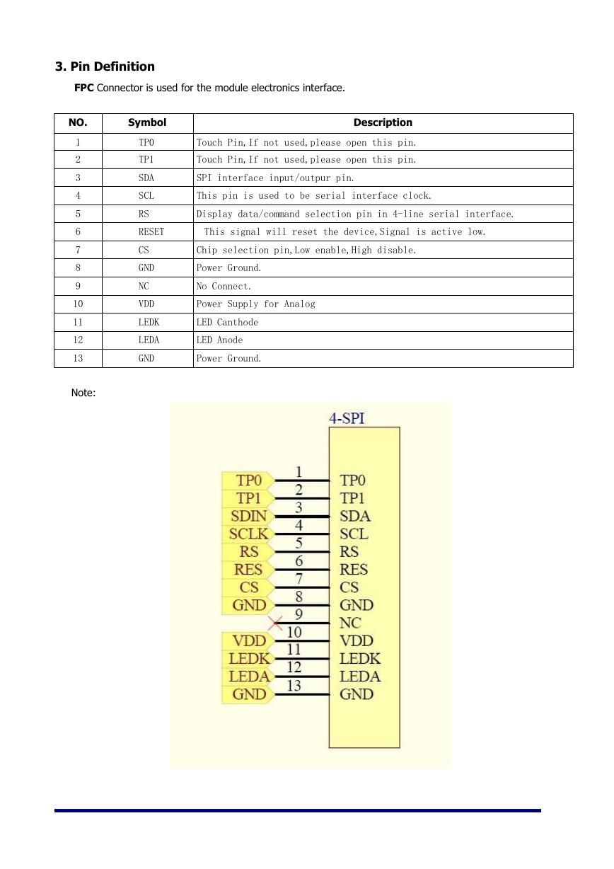
3. Pin Definition
FPC Connector is used for the module electronics interface.
Symbol
TP0
TP1
SDA
SCL
RS
Description
Touch Pin,If not used,please open this pin.
Touch Pin,If not used,please open this pin.
SPI interface input/outpur pin.
This pin is used to be serial interface clock.
Display data/command selection pin in 4-line serial interface.
RESET
This signal will reset the device,Signal is active low.
CS
GND
NC
VDD
LEDK
LEDA
GND
Chip selection pin,Low enable,High disable.
Power Ground.
No Connect.
Power Supply for Analog
LED Canthode
LED Anode
Power Ground.
NO.
1
2
3
4
5
6
7
8
9
10
11
12
13
Note:
�
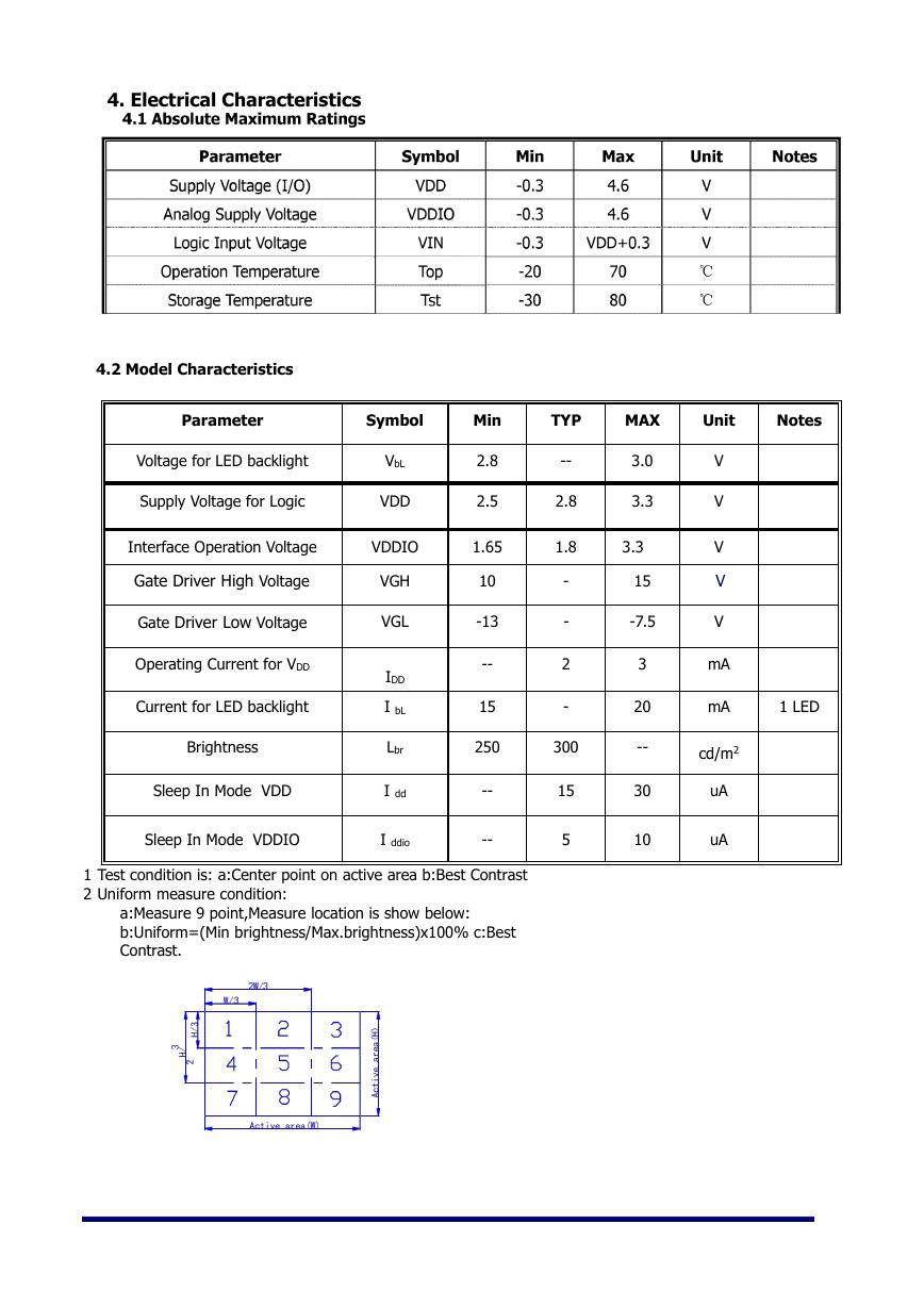
4. Electrical Characteristics
4.2 Model Characteristics
Parameter
Symbol
Voltage for LED backlight
Supply Voltage for Logic
Interface Operation Voltage
Gate Driver High Voltage
Gate Driver Low Voltage
Operating Current for VDD
Current for LED backlight
Brightness
Sleep In Mode VDD
VbL
VDD
VDDIO
VGH
VGL
IDD
I bL
Lbr
I dd
Sleep In Mode VDDIO
I ddio
Min
2.8
2.5
1.65
10
-13
--
15
250
--
--
1 Test condition is: a:Center point on active area b:Best Contrast
2 Uniform measure condition:
a:Measure 9 point,Measure location is show below:
b:Uniform=(Min brightness/Max.brightness)x100% c:Best
Contrast.
TYP
MAX
Unit
Notes
--
2.8
1.8
-
-
2
-
300
15
5
3.0
3.3
3.3
15
-7.5
3
20
--
30
10
V
V
V
V
V
mA
mA
cd/m2
uA
uA
1 LED
�
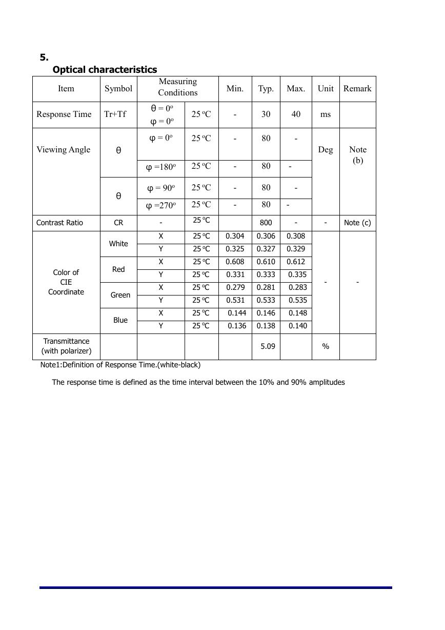
5.
Optical characteristics
Item
Symbol
Response Time
Tr+Tf
Viewing Angle
Contrast Ratio
Color of
CIE
Coordinate
θ
θ
CR
White
Red
Green
Blue
Measuring
Conditions
θ = 0o
φ = 0o
φ = 0o
φ =180o
φ = 90o
φ =270o
-
X
Y
X
Y
X
Y
X
Y
25 oC
25 oC
25 oC
25 oC
25 oC
25 oC
25 oC
25 oC
25 oC
25 oC
25 oC
25 oC
25 oC
25 oC
Min.
Typ. Max. Unit Remark
-
-
-
-
-
0.304
0.325
0.608
0.331
0.279
0.531
0.144
0.136
30
80
80
80
80
800
0.306
0.327
0.610
0.333
0.281
0.533
0.146
0.138
5.09
40
ms
-
-
-
-
-
0.308
0.329
0.612
0.335
0.283
0.535
0.148
0.140
Deg
Note
(b)
Note (c)
-
-
-
%
Transmittance
(with polarizer)
Note1:Definition of Response Time.(white-black)
The response time is defined as the time interval between the 10% and 90% amplitudes
�
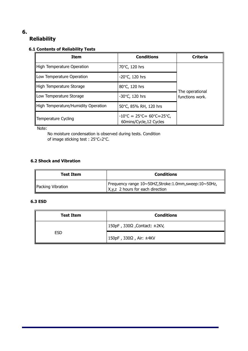
6.
Reliability
6.1 Contents of Reliability Tests
Item
Conditions
Criteria
High Temperature Operation
Low Temperature Operation
High Temperature Storage
Low Temperature Storage
High Temperature/Humidity Operation
Temperature Cycling
70°C, 120 hrs
-20°C, 120 hrs
80°C, 120 hrs
-30°C, 120 hrs
50°C, 85% RH, 120 hrs
-10°C ⇔ 25°C⇔ 60°C⇔25°C,
60mins/Cycle,12 Cycles
Note:
No moisture condensation is observed during tests. Condition
of image sticking test : 25°C±2°C.
The operational
functions work.
6.2 Shock and Vibration
Test Item
Conditions
Packing Vibration
6.3 ESD
Frequency range 10~50HZ,Stroke:1.0mm,sweep:10~50Hz,
X,y,z 2 hours for each direction
Test Item
ESD
Conditions
150pF , 330Ω ,Contact: ±2KV,
150pF , 330Ω , Air: ±4KV
�


 V2版本原理图(Capacitive-Fingerprint-Reader-Schematic_V2).pdf
 摄像头工作原理.doc
 VL53L0X简要说明(En.FLVL53L00216).pdf
 原理图(DVK720-Schematic).pdf
 原理图(Pico-Clock-Green-Schdoc).pdf
 原理图(RS485-CAN-HAT-B-schematic).pdf
 File:SIM7500_SIM7600_SIM7800 Series_SSL_Application Note_V2.00.pdf
 ADS1263(Ads1262).pdf
 原理图(Open429Z-D-Schematic).pdf
 用户手册(Capacitive_Fingerprint_Reader_User_Manual_CN).pdf
 CY7C68013A(英文版)(CY7C68013A).pdf
 TechnicalReference_Dem.pdf