logo资料库

SSD1331 手册(SSD1331-Revision_1.2).pdf

第1页 / 共68页
第2页 / 共68页
第3页 / 共68页
第4页 / 共68页
第5页 / 共68页
第6页 / 共68页
第7页 / 共68页
第8页 / 共68页
资料共68页,剩余部分请下载后查看
1 GERENAL INFORMATION
2 FEATURES
3 ORDERING INFORMATION
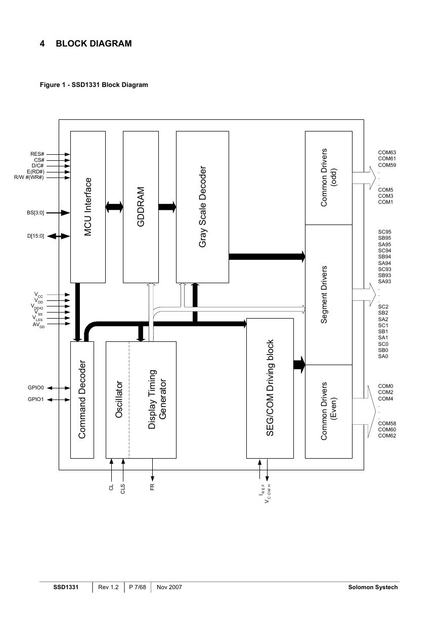
4 BLOCK DIAGRAM
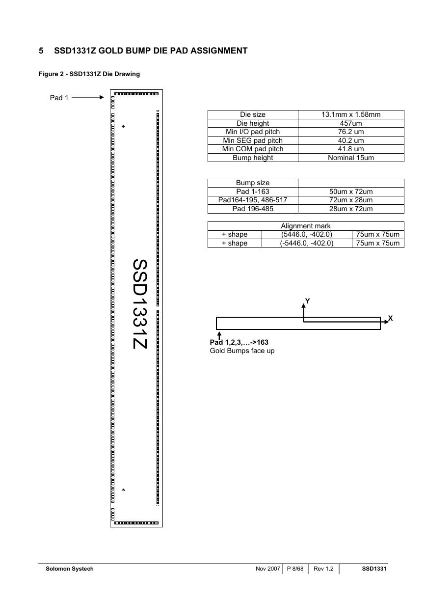
5 SSD1331Z GOLD BUMP DIE PAD ASSIGNMENT
6 PIN DESCRIPTION
7 FUNCTIONAL BLOCK DESCRIPTIONS
7.1 MCU Interface Selection
7.1.1 6800-series Parallel Interface
7.1.2 8080-series Parallel Interface
7.1.3 Serial Interface
7.2 Command Decoder
7.3 Oscillator Circuit and Display Time Generator
7.3.1 Oscillator
7.3.2 FR synchronization
7.4 Reset Circuit
7.5 Graphic Display Data RAM (GDDRAM)
7.5.1 GDDRAM structure
7.5.2 Data bus to RAM mapping under different input mode
7.5.3 RAM mapping and Different color depth mode
7.6 Gray Scale Decoder
7.7 SEG / COM Driving block
7.8 Common and Segment Drivers
7.9 Power ON and OFF sequence
8 COMMAND TABLE
8.1 Data Read / Write
9 COMMAND DESCRIPTIONS
9.1 Fundamental Command
9.1.1 Set Column Address (15h)
9.1.2 Set Row Address (75h)
9.1.3 Set Contrast for Color A, B, C (81h, 82h, 83h)
9.1.4 Master Current Control (87h)
9.1.5 Set Second Pre-charge Speed for Color A, B, C (8Ah)
9.1.6 Set Re-map & Data Format (A0h)
9.1.7 Set Display Start Line (A1h)
9.1.8 Set Display Offset (A2h)
9.1.9 Set Display Mode (A4h ~ A7h)
9.1.10 Set Multiplex Ratio (A8h)
9.1.11 Dim mode setting (ABh)
9.1.12 Set Master Configuration (ADh)
9.1.13 Set Display ON/OFF (ACh / AEh / AFh)
9.1.14 Power Save Mode (B0h)
9.1.15 Phase 1 and 2 Period Adjustment (B1h)
9.1.16 Set Display Clock Divide Ratio/ Oscillator Frequency (B3h)
9.1.17 Set Gray Scale Table (B8h)
9.1.18 Enable Linear Gray Scale Table (B9h)
9.1.19 Set Pre-charge voltage (BBh)
9.1.20 Set VCOMH Voltage (BEh)
9.1.21 NOP (BCh, BDh, E3h)
9.1.22 Set Command Lock (FDh)
9.2 GRAPHIC ACCELERATION COMMAND SET DESCRIPTION
9.2.1 Draw Line (21h)
9.2.2 Draw Rectangle (22h)
9.2.3 Copy (23h)
9.2.4 Dim Window (24h)
9.2.5 Clear Window (25h)
9.2.6 Fill Enable/Disable (26h)
9.2.7 Continuous Horizontal & Vertical Scrolling Setup (27h)
9.2.8 Deactivate scrolling (2Eh)
9.2.9 Activate scrolling (2Fh)
10 MAXIMUM RATINGS
11 DC CHARACTERISTICS
12 AC CHARACTERISTICS
13 APPLICATION EXAMPLE
14 PACKAGE OPTIONS
14.1 SSD1331Z Die Tray Information
14.2 SSD1331U1R1 COF PACKAGE DIMENSIONS
14.3 SSD1331U1R1 COF PACKAGE PIN ASSIGNMENT
14.4 SSD1331U3R1 COF PACKAGE DIMENSIONS
14.5 SSD1331U3R1 COF PACKAGE PIN ASSIGNMENT
SOLOMON SYSTECH SEMICONDUCTOR TECHNICAL DATA SSD1331 Advance Information 96RGB x 64 Dot Matrix OLED/PLED Segment/Common Driver with Controller This document contains information on a new product. Specifications and information herein are subject to change without notice. http://www.solomon-systech.com SSD1331 Copyright © 2007 Solomon Systech Limited P 1/68 Nov 2007 Rev 1.2
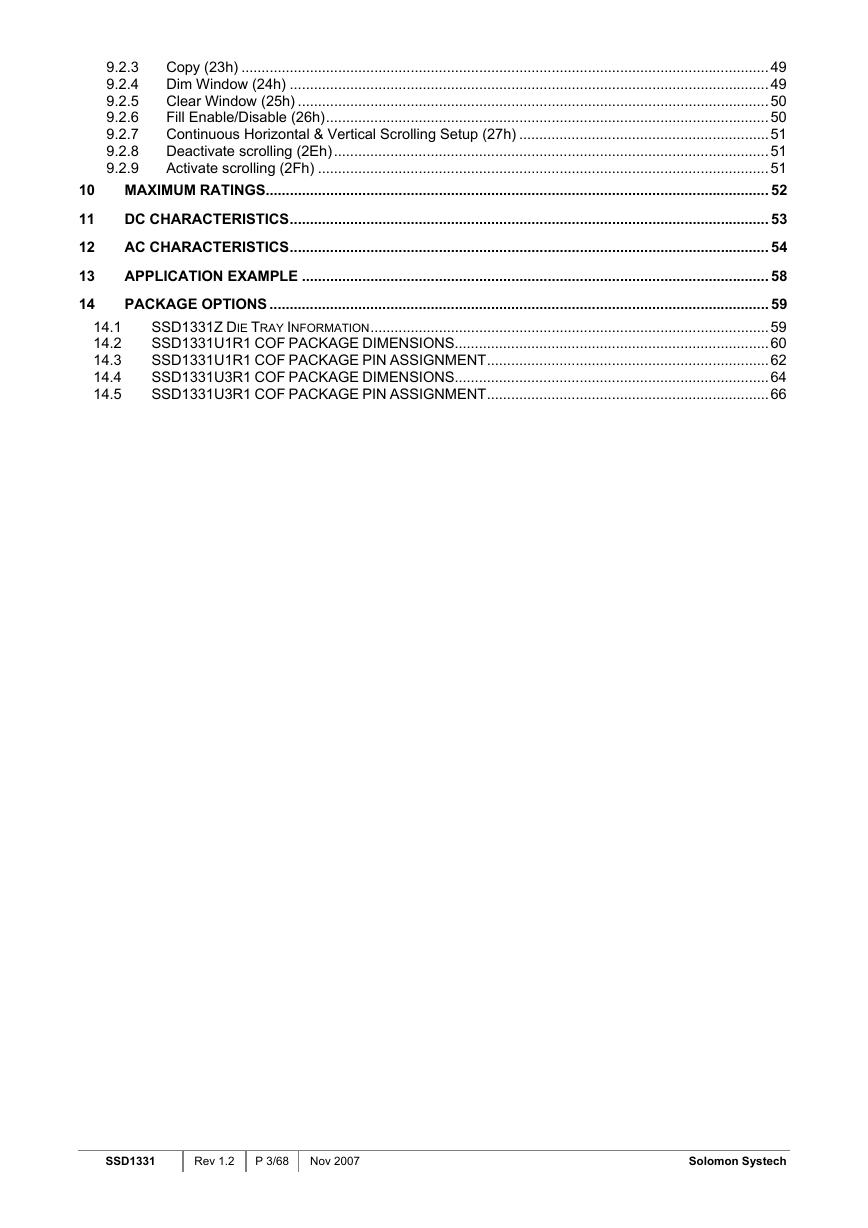
7.3.1 7.3.2 7.1.1 7.1.2 7.1.3 7.5.1 7.5.2 7.5.3 CONTENTS CONTENTS......................................................................................................................................................... 2 GERENAL INFORMATION ..................................................................................................................... 6 1 FEATURES.............................................................................................................................................. 6 2 3 ORDERING INFORMATION ................................................................................................................... 6 BLOCK DIAGRAM .................................................................................................................................. 7 4 5 SSD1331Z GOLD BUMP DIE PAD ASSIGNMENT................................................................................ 8 PIN DESCRIPTION................................................................................................................................ 12 6 FUNCTIONAL BLOCK DESCRIPTIONS.............................................................................................. 15 7 7.1 MCU INTERFACE SELECTION .................................................................................................................15 6800-series Parallel Interface ......................................................................................................15 8080-series Parallel Interface ......................................................................................................16 Serial Interface.............................................................................................................................17 7.2 COMMAND DECODER.............................................................................................................................18 7.3 OSCILLATOR CIRCUIT AND DISPLAY TIME GENERATOR ............................................................................18 Oscillator ......................................................................................................................................18 FR synchronization ......................................................................................................................19 7.4 RESET CIRCUIT .....................................................................................................................................19 7.5 GRAPHIC DISPLAY DATA RAM (GDDRAM)............................................................................................20 GDDRAM structure......................................................................................................................20 Data bus to RAM mapping under different input mode ...............................................................20 RAM mapping and Different color depth mode............................................................................21 7.6 GRAY SCALE DECODER .........................................................................................................................21 7.7 SEG / COM DRIVING BLOCK..................................................................................................................23 7.8 COMMON AND SEGMENT DRIVERS..........................................................................................................24 7.9 POWER ON AND OFF SEQUENCE...........................................................................................................27 COMMAND TABLE ............................................................................................................................... 28 8.1 DATA READ / WRITE ..............................................................................................................................34 COMMAND DESCRIPTIONS................................................................................................................ 35 FUNDAMENTAL COMMAND......................................................................................................................35 Set Column Address (15h)...........................................................................................................35 9.1.1 9.1.2 Set Row Address (75h)................................................................................................................35 Set Contrast for Color A, B, C (81h, 82h, 83h) ...........................................................................36 9.1.3 9.1.4 Master Current Control (87h).......................................................................................................36 9.1.5 Set Second Pre-charge Speed for Color A, B, C (8Ah)...............................................................37 Set Re-map & Data Format (A0h) ...............................................................................................37 9.1.6 Set Display Start Line (A1h).........................................................................................................42 9.1.7 9.1.8 Set Display Offset (A2h) ..............................................................................................................42 9.1.9 Set Display Mode (A4h ~ A7h) ....................................................................................................45 9.1.10 Set Multiplex Ratio (A8h) .............................................................................................................45 9.1.11 Dim mode setting (ABh)...............................................................................................................45 9.1.12 Set Master Configuration (ADh)...................................................................................................45 9.1.13 Set Display ON/OFF (ACh / AEh / AFh) ......................................................................................45 9.1.14 Power Save Mode (B0h)..............................................................................................................46 9.1.15 Phase 1 and 2 Period Adjustment (B1h) .....................................................................................46 9.1.16 Set Display Clock Divide Ratio/ Oscillator Frequency (B3h) .......................................................46 9.1.17 Set Gray Scale Table (B8h).........................................................................................................46 9.1.18 Enable Linear Gray Scale Table (B9h)........................................................................................47 9.1.19 Set Pre-charge voltage (BBh)......................................................................................................47 9.1.20 Set VCOMH Voltage (BEh)..............................................................................................................47 9.1.21 NOP (BCh, BDh, E3h) .................................................................................................................47 9.1.22 Set Command Lock (FDh) ...........................................................................................................47 9.2 GRAPHIC ACCELERATION COMMAND SET DESCRIPTION..........................................................48 Draw Line (21h) ...........................................................................................................................48 9.2.1 Draw Rectangle (22h)..................................................................................................................48 9.2.2 8 9 9.1 Solomon Systech Nov 2007 P 2/68 Rev 1.2 SSD1331
10 11 12 13 14 9.2.3 9.2.4 9.2.5 9.2.6 9.2.7 9.2.8 9.2.9 Copy (23h) ...................................................................................................................................49 Dim Window (24h) .......................................................................................................................49 Clear Window (25h) .....................................................................................................................50 Fill Enable/Disable (26h)..............................................................................................................50 Continuous Horizontal & Vertical Scrolling Setup (27h) ..............................................................51 Deactivate scrolling (2Eh)............................................................................................................51 Activate scrolling (2Fh) ................................................................................................................51 MAXIMUM RATINGS............................................................................................................................. 52 DC CHARACTERISTICS....................................................................................................................... 53 AC CHARACTERISTICS....................................................................................................................... 54 APPLICATION EXAMPLE .................................................................................................................... 58 PACKAGE OPTIONS ............................................................................................................................ 59 SSD1331Z DIE TRAY INFORMATION...................................................................................................59 SSD1331U1R1 COF PACKAGE DIMENSIONS..............................................................................60 SSD1331U1R1 COF PACKAGE PIN ASSIGNMENT......................................................................62 SSD1331U3R1 COF PACKAGE DIMENSIONS..............................................................................64 SSD1331U3R1 COF PACKAGE PIN ASSIGNMENT......................................................................66 14.1 14.2 14.3 14.4 14.5 SSD1331 Rev 1.2 P 3/68 Nov 2007 Solomon Systech
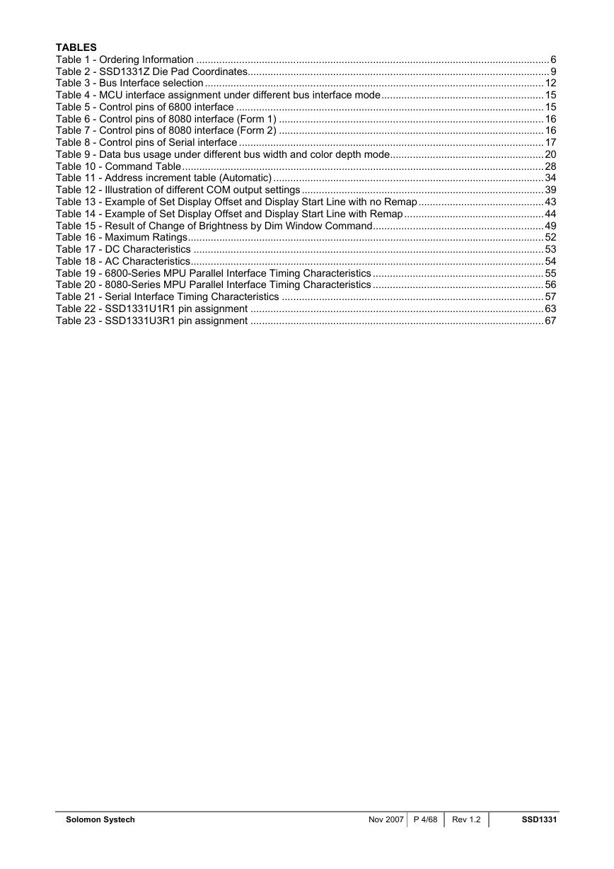
TABLES Table 1 - Ordering Information ............................................................................................................................6 Table 2 - SSD1331Z Die Pad Coordinates..........................................................................................................9 Table 3 - Bus Interface selection.......................................................................................................................12 Table 4 - MCU interface assignment under different bus interface mode.........................................................15 Table 5 - Control pins of 6800 interface ............................................................................................................15 Table 6 - Control pins of 8080 interface (Form 1) .............................................................................................16 Table 7 - Control pins of 8080 interface (Form 2) .............................................................................................16 Table 8 - Control pins of Serial interface ...........................................................................................................17 Table 9 - Data bus usage under different bus width and color depth mode......................................................20 Table 10 - Command Table...............................................................................................................................28 Table 11 - Address increment table (Automatic) ...............................................................................................34 Table 12 - Illustration of different COM output settings.....................................................................................39 Table 13 - Example of Set Display Offset and Display Start Line with no Remap............................................43 Table 14 - Example of Set Display Offset and Display Start Line with Remap.................................................44 Table 15 - Result of Change of Brightness by Dim Window Command............................................................49 Table 16 - Maximum Ratings.............................................................................................................................52 Table 17 - DC Characteristics ...........................................................................................................................53 Table 18 - AC Characteristics............................................................................................................................54 Table 19 - 6800-Series MPU Parallel Interface Timing Characteristics ............................................................55 Table 20 - 8080-Series MPU Parallel Interface Timing Characteristics ............................................................56 Table 21 - Serial Interface Timing Characteristics ............................................................................................57 Table 22 - SSD1331U1R1 pin assignment .......................................................................................................63 Table 23 - SSD1331U3R1 pin assignment .......................................................................................................67 Solomon Systech Nov 2007 P 4/68 Rev 1.2 SSD1331
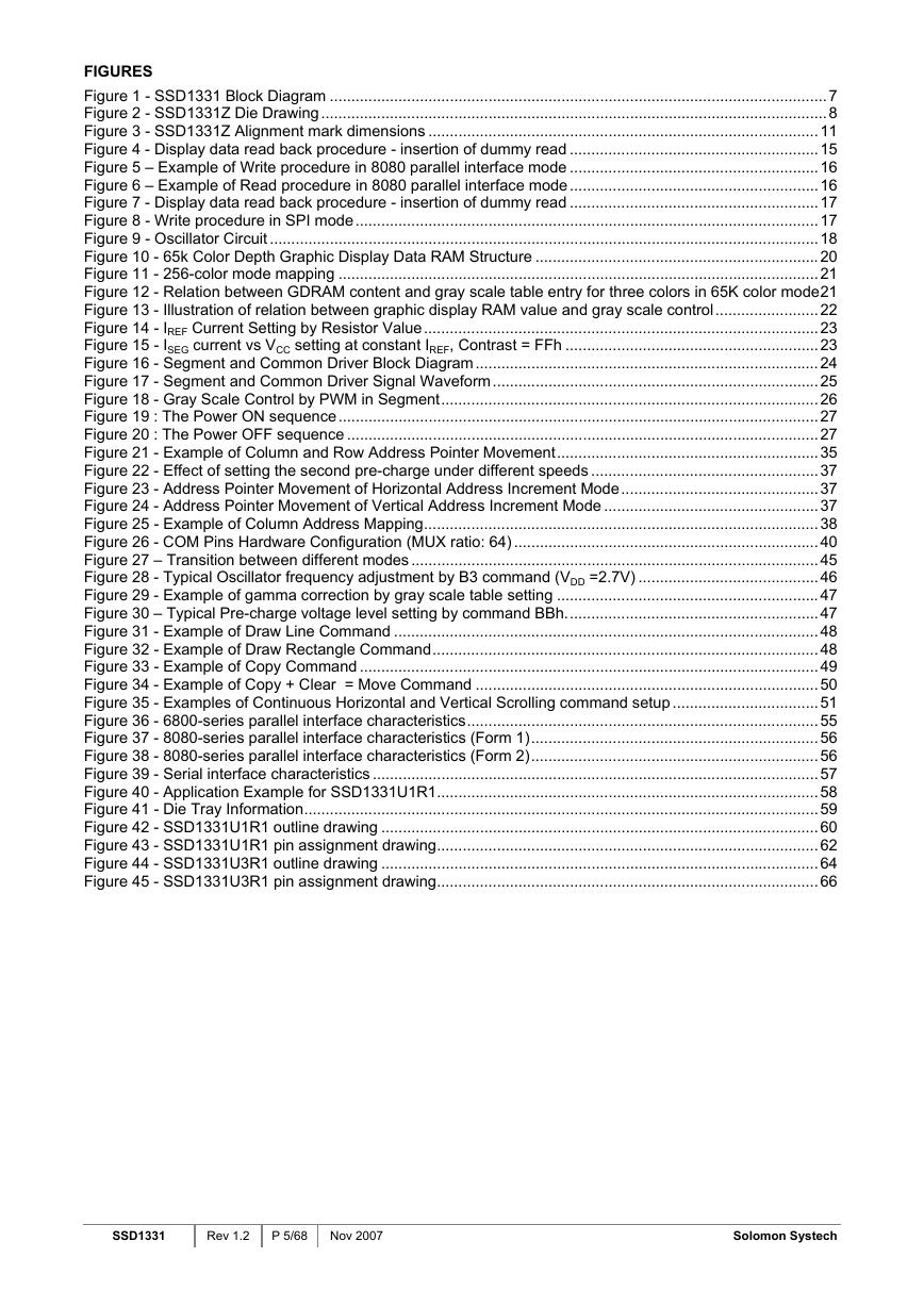
FIGURES Figure 1 - SSD1331 Block Diagram ....................................................................................................................7 Figure 2 - SSD1331Z Die Drawing......................................................................................................................8 Figure 3 - SSD1331Z Alignment mark dimensions ...........................................................................................11 Figure 4 - Display data read back procedure - insertion of dummy read ..........................................................15 Figure 5 – Example of Write procedure in 8080 parallel interface mode ..........................................................16 Figure 6 – Example of Read procedure in 8080 parallel interface mode..........................................................16 Figure 7 - Display data read back procedure - insertion of dummy read ..........................................................17 Figure 8 - Write procedure in SPI mode............................................................................................................17 Figure 9 - Oscillator Circuit ................................................................................................................................18 Figure 10 - 65k Color Depth Graphic Display Data RAM Structure ..................................................................20 Figure 11 - 256-color mode mapping ................................................................................................................21 Figure 12 - Relation between GDRAM content and gray scale table entry for three colors in 65K color mode21 Figure 13 - Illustration of relation between graphic display RAM value and gray scale control........................22 Figure 14 - IREF Current Setting by Resistor Value............................................................................................23 Figure 15 - ISEG current vs VCC setting at constant IREF, Contrast = FFh ...........................................................23 Figure 16 - Segment and Common Driver Block Diagram................................................................................24 Figure 17 - Segment and Common Driver Signal Waveform............................................................................25 Figure 18 - Gray Scale Control by PWM in Segment........................................................................................26 Figure 19 : The Power ON sequence................................................................................................................27 Figure 20 : The Power OFF sequence ..............................................................................................................27 Figure 21 - Example of Column and Row Address Pointer Movement.............................................................35 Figure 22 - Effect of setting the second pre-charge under different speeds .....................................................37 Figure 23 - Address Pointer Movement of Horizontal Address Increment Mode..............................................37 Figure 24 - Address Pointer Movement of Vertical Address Increment Mode ..................................................37 Figure 25 - Example of Column Address Mapping............................................................................................38 Figure 26 - COM Pins Hardware Configuration (MUX ratio: 64) .......................................................................40 Figure 27 – Transition between different modes ...............................................................................................45 Figure 28 - Typical Oscillator frequency adjustment by B3 command (VDD =2.7V) ..........................................46 Figure 29 - Example of gamma correction by gray scale table setting .............................................................47 Figure 30 – Typical Pre-charge voltage level setting by command BBh...........................................................47 Figure 31 - Example of Draw Line Command ...................................................................................................48 Figure 32 - Example of Draw Rectangle Command..........................................................................................48 Figure 33 - Example of Copy Command ...........................................................................................................49 Figure 34 - Example of Copy + Clear = Move Command ................................................................................50 Figure 35 - Examples of Continuous Horizontal and Vertical Scrolling command setup ..................................51 Figure 36 - 6800-series parallel interface characteristics..................................................................................55 Figure 37 - 8080-series parallel interface characteristics (Form 1)...................................................................56 Figure 38 - 8080-series parallel interface characteristics (Form 2)...................................................................56 Figure 39 - Serial interface characteristics ........................................................................................................57 Figure 40 - Application Example for SSD1331U1R1.........................................................................................58 Figure 41 - Die Tray Information........................................................................................................................59 Figure 42 - SSD1331U1R1 outline drawing ......................................................................................................60 Figure 43 - SSD1331U1R1 pin assignment drawing.........................................................................................62 Figure 44 - SSD1331U3R1 outline drawing ......................................................................................................64 Figure 45 - SSD1331U3R1 pin assignment drawing.........................................................................................66 SSD1331 Rev 1.2 P 5/68 Nov 2007 Solomon Systech
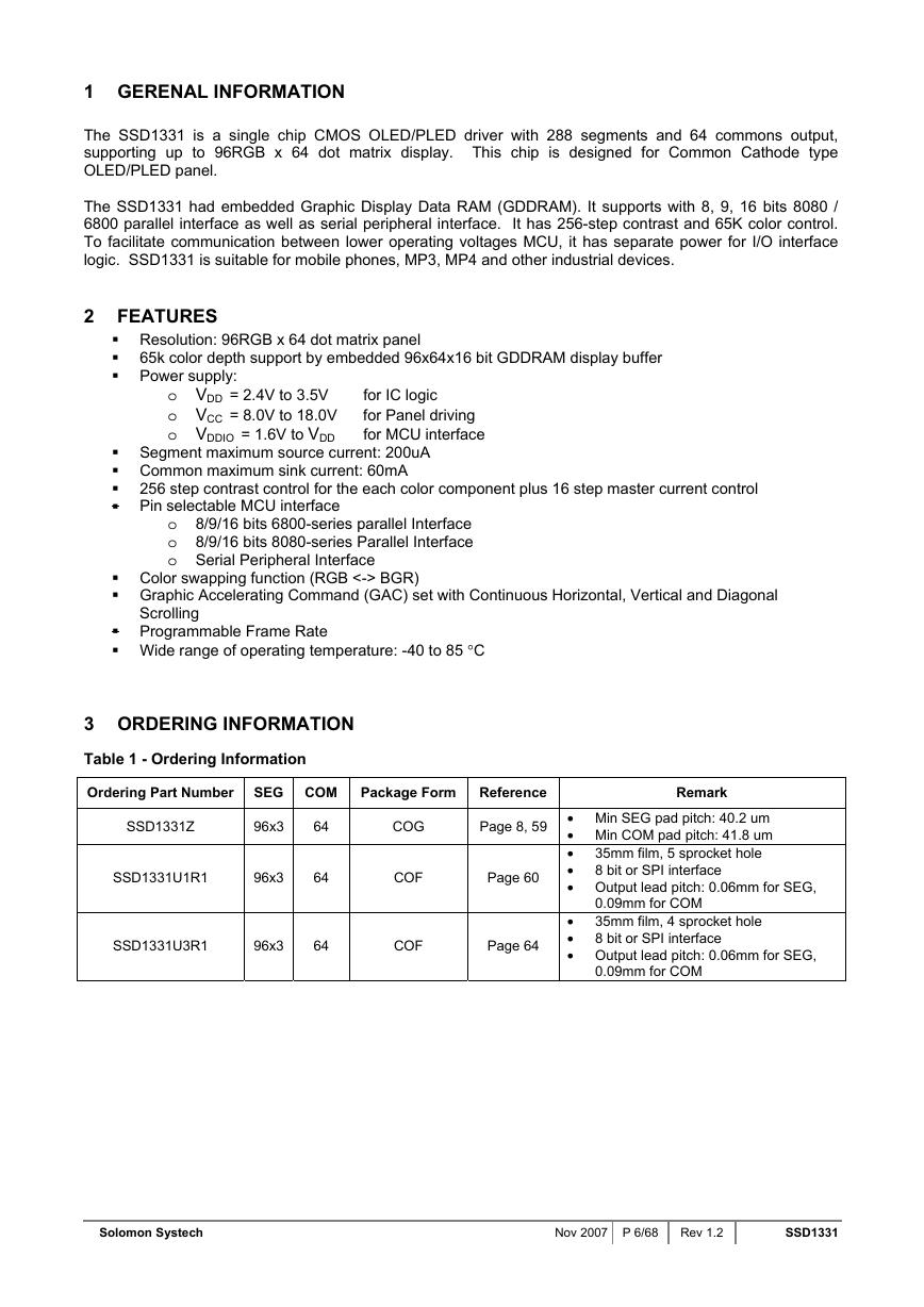
1 GERENAL INFORMATION The SSD1331 is a single chip CMOS OLED/PLED driver with 288 segments and 64 commons output, supporting up to 96RGB x 64 dot matrix display. This chip is designed for Common Cathode type OLED/PLED panel. The SSD1331 had embedded Graphic Display Data RAM (GDDRAM). It supports with 8, 9, 16 bits 8080 / 6800 parallel interface as well as serial peripheral interface. It has 256-step contrast and 65K color control. To facilitate communication between lower operating voltages MCU, it has separate power for I/O interface logic. SSD1331 is suitable for mobile phones, MP3, MP4 and other industrial devices. 2 FEATURES Resolution: 96RGB x 64 dot matrix panel 65k color depth support by embedded 96x64x16 bit GDDRAM display buffer Power supply: o VDD = 2.4V to 3.5V o VCC = 8.0V to 18.0V o VDDIO = 1.6V to VDD for IC logic for Panel driving for MCU interface Segment maximum source current: 200uA Common maximum sink current: 60mA 256 step contrast control for the each color component plus 16 step master current control Pin selectable MCU interface Color swapping function (RGB <-> BGR) Graphic Accelerating Command (GAC) set with Continuous Horizontal, Vertical and Diagonal o 8/9/16 bits 6800-series parallel Interface o 8/9/16 bits 8080-series Parallel Interface o Serial Peripheral Interface Scrolling Programmable Frame Rate Wide range of operating temperature: -40 to 85 °C 3 ORDERING INFORMATION Table 1 - Ordering Information Ordering Part Number SEG COM Package Form Reference Remark SSD1331Z 96x3 64 COG Page 8, 59 SSD1331U1R1 96x3 64 COF Page 60 SSD1331U3R1 96x3 64 COF Page 64 • Min SEG pad pitch: 40.2 um • Min COM pad pitch: 41.8 um • • • Output lead pitch: 0.06mm for SEG, 35mm film, 5 sprocket hole 8 bit or SPI interface 0.09mm for COM 35mm film, 4 sprocket hole 8 bit or SPI interface • • • Output lead pitch: 0.06mm for SEG, 0.09mm for COM Solomon Systech Nov 2007 P 6/68 Rev 1.2 SSD1331
4 BLOCK DIAGRAM Figure 1 - SSD1331 Block Diagram RES# CS# D/C# E(RD#) R/W #(WR#) BS[3:0] D[15:0] VCCVDD VDDIO VSSVLSS AVDD GPIO0 GPIO1 e c a f r e n t I U C M M A R D D G r e d o c e D e a c S y a r G l s r e v i r ) d d o ( D n o m m o C s r e v i r D t n e m g e S r e d o c e D d n a m m o C r o t a l l i c s O i i g n m T y a p s D i l r o t a r e n e G L C S L C R F k c o b l g n v i r i D M O C G E S / F E R H M O C V I ) n e v E ( s r e v i r D n o m m o C COM63 COM61 COM59 . . . COM5 COM3 COM1 SC95 SB95 SA95 SC94 SB94 SA94 SC93 SB93 SA93 . . . SC2 SB2 SA2 SC1 SB1 SA1 SC0 SB0 SA0 COM0 COM2 COM4 . . . COM58 COM60 COM62 SSD1331 Rev 1.2 P 7/68 Nov 2007 Solomon Systech
5 SSD1331Z GOLD BUMP DIE PAD ASSIGNMENT Figure 2 - SSD1331Z Die Drawing Pad 1 Die size Die height Min I/O pad pitch Min SEG pad pitch Min COM pad pitch Bump height 13.1mm x 1.58mm 457um 76.2 um 40.2 um 41.8 um Nominal 15um Bump size Pad 1-163 Pad164-195, 486-517 Pad 196-485 50um x 72um 72um x 28um 28um x 72um + shape + shape Alignment mark (5446.0, -402.0) (-5446.0, -402.0) 75um x 75um 75um x 75um S S D 1 3 3 1 Z Y X Pad 1,2,3,…->163 Gold Bumps face up Solomon Systech Nov 2007 P 8/68 Rev 1.2 SSD1331
分享到:
收藏