Toshiba Bi-CD Integrated Circuit Silicon Monolithic
TB6612FNG
TB6612FNG
Driver IC for Dual DC motor
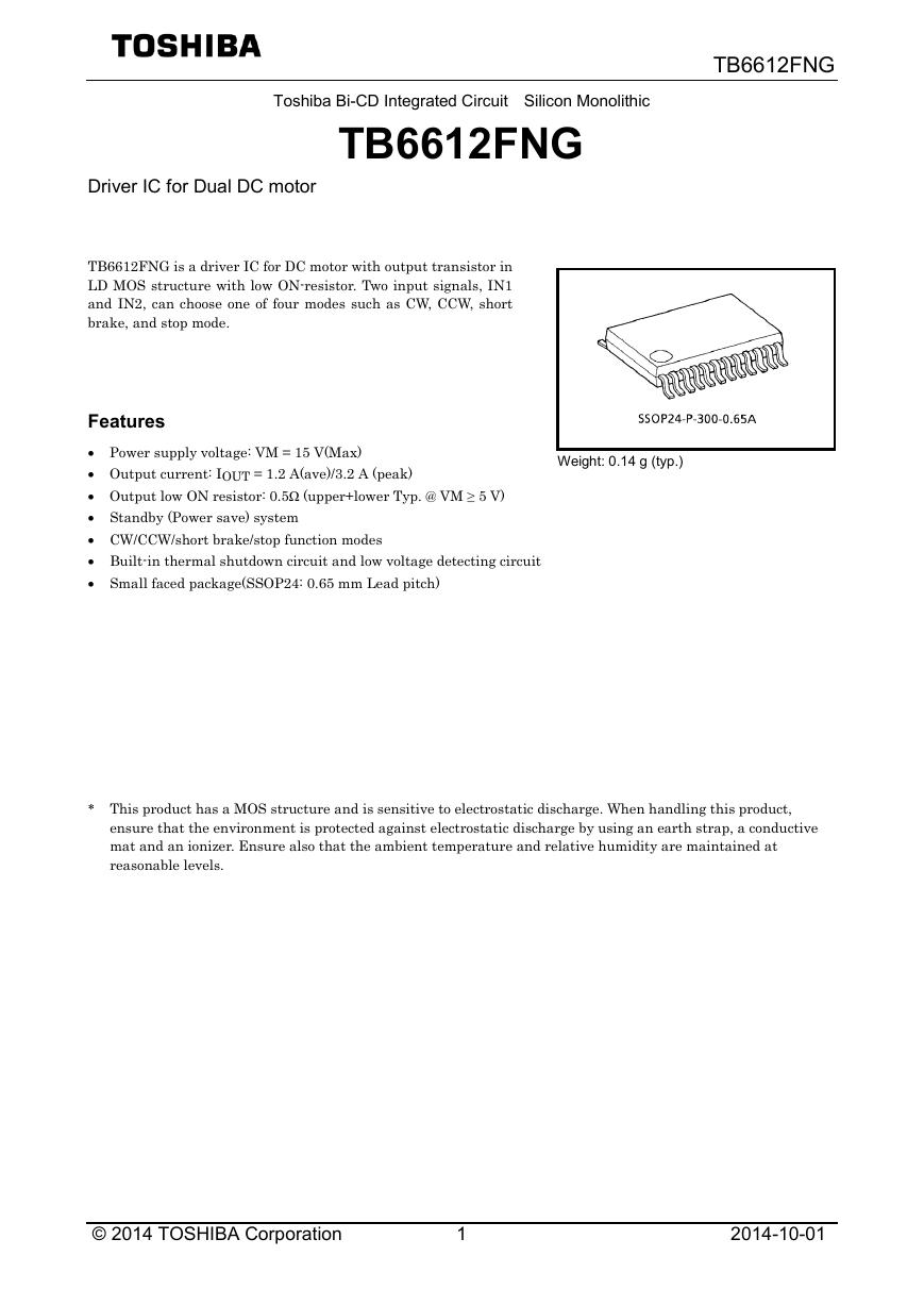
TB6612FNG is a driver IC for DC motor with output transistor in
LD MOS structure with low ON-resistor. Two input signals, IN1
and IN2, can choose one of four modes such as CW, CCW, short
brake, and stop mode.
Features
• Power supply voltage: VM = 15 V(Max)
• Output current: IOUT = 1.2 A(ave)/3.2 A (peak)
• Output low ON resistor: 0.5Ω (upper+lower Typ. @ VM ≥ 5 V)
• Standby (Power save) system
• CW/CCW/short brake/stop function modes
• Built-in thermal shutdown circuit and low voltage detecting circuit
• Small faced package(SSOP24: 0.65 mm Lead pitch)
* This product has a MOS structure and is sensitive to electrostatic discharge. When handling this product,
Weight: 0.14 g (typ.)
ensure that the environment is protected against electrostatic discharge by using an earth strap, a conductive
mat and an ionizer. Ensure also that the ambient temperature and relative humidity are maintained at
reasonable levels.
© 2014 TOSHIBA Corporation
1
2014-10-01
�
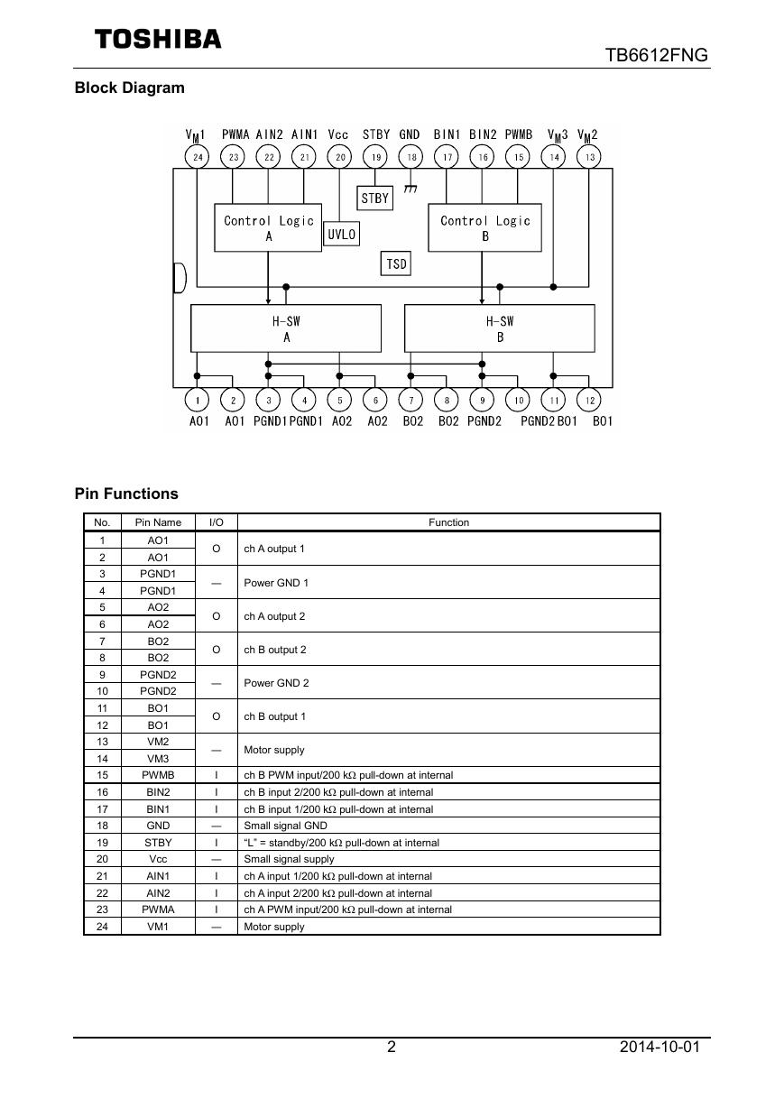
Block Diagram
TB6612FNG
Pin Functions
Pin Name
No.
1
2
3
4
5
6
7
8
9
10
11
12
13
14
15
16
17
18
19
20
21
22
23
24
AO1
AO1
PGND1
PGND1
AO2
AO2
BO2
BO2
PGND2
PGND2
BO1
BO1
VM2
VM3
PWMB
BIN2
BIN1
GND
STBY
Vcc
AIN1
AIN2
PWMA
VM1
Function
I/O
O
ch A output 1
―
Power GND 1
O
O
ch A output 2
ch B output 2
―
Power GND 2
O
ch B output 1
―
I
I
I
―
I
―
I
I
I
―
Motor supply
ch B PWM input/200 kΩ pull-down at internal
ch B input 2/200 kΩ pull-down at internal
ch B input 1/200 kΩ pull-down at internal
Small signal GND
“L” = standby/200 kΩ pull-down at internal
Small signal supply
ch A input 1/200 kΩ pull-down at internal
ch A input 2/200 kΩ pull-down at internal
ch A PWM input/200 kΩ pull-down at internal
Motor supply
2
2014-10-01
�
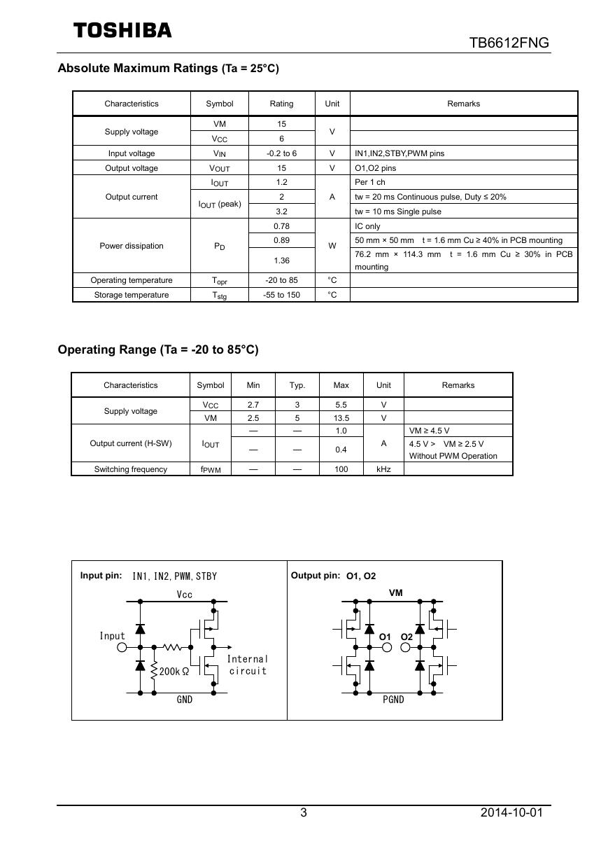
Absolute Maximum Ratings (Ta = 25°C)
Characteristics
Symbol
Rating
Unit
Remarks
TB6612FNG
Supply voltage
Input voltage
Output voltage
Output current
VM
VCC
VIN
VOUT
IOUT
IOUT (peak)
Power dissipation
Operating temperature
Storage temperature
PD
Topr
Tstg
Operating Range (Ta = -20 to 85°C)
15
6
-0.2 to 6
15
1.2
2
3.2
0.78
0.89
1.36
-20 to 85
-55 to 150
V
V
V
A
W
°C
°C
IN1,IN2,STBY,PWM pins
O1,O2 pins
Per 1 ch
tw = 20 ms Continuous pulse, Duty ≤ 20%
tw = 10 ms Single pulse
IC only
50 mm × 50 mm t = 1.6 mm Cu ≥ 40% in PCB mounting
76.2 mm × 114.3 mm t = 1.6 mm Cu ≥ 30% in PCB
mounting
Characteristics
Symbol
Min
Typ.
Supply voltage
Output current (H-SW)
VCC
VM
IOUT
Switching frequency
fPWM
2.7
2.5
―
―
―
3
5
―
―
―
Max
5.5
13.5
1.0
0.4
100
Unit
Remarks
V
V
A
kHz
VM ≥ 4.5 V
4.5 V > VM ≥ 2.5 V
Without PWM Operation
Input pin:
入力端子; IN1,IN2,PWM,STBY
Output pin: O1, O2
出力端子; O1,O2
Input
Vcc
200kΩ
GND
Internal
circuit
VM
VM
O1 O2
O1 O2
PGND
3
2014-10-01
�
TB6612FNG
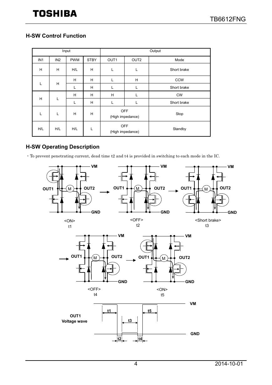
H-SW Control Function
Input
IN1
IN2
PWM
STBY
OUT1
OUT2
H
L
H
L
H
H
L
L
H/L
H
L
H
L
H
H/L
H/L
H/L
H
H
H
H
H
H
L
L
L
L
H
L
L
H
L
L
L
OFF
(High impedance)
OFF
(High impedance)
Output
Mode
Short brake
CCW
Short brake
CW
Short brake
Stop
Standby
VM
VM
M
OUT2
GND
t3
GND
GND
VM
OUT2
OUT1
M
OUT1
M
OUT2
OUT1
t2
t1
H-SW Operating Description
・To prevent penetrating current, dead time t2 and t4 is provided in switching to each mode in the IC.
Voltage wave
t4
t5
t2
t4
OUT2
OUT1
M
OUT2
OUT1
M
t1
t5
GND
VM
OUT1
VM
VM
GND
GND
t3
4
2014-10-01
�
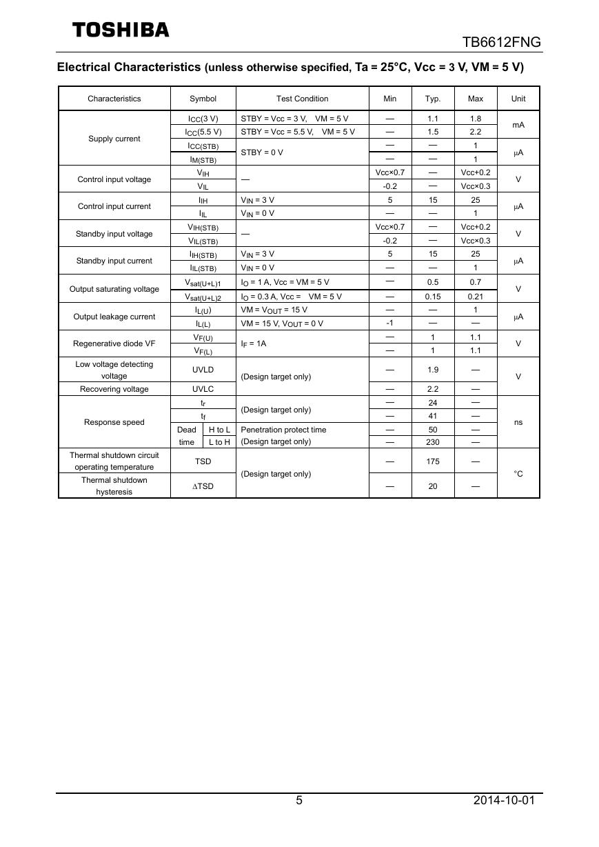
Electrical Characteristics (unless otherwise specified, Ta = 25°C, Vcc = 3 V, VM = 5 V)
TB6612FNG
Characteristics
Supply current
Control input voltage
Control input current
Standby input voltage
Standby input current
Output saturating voltage
Output leakage current
Regenerative diode VF
Low voltage detecting
voltage
Recovering voltage
Response speed
Symbol
ICC(3 V)
ICC(5.5 V)
ICC(STB)
IM(STB)
VIH
VIL
IIH
IIL
VIH(STB)
VIL(STB)
IIH(STB)
IIL(STB)
Vsat(U+L)1
Vsat(U+L)2
IL(U)
IL(L)
VF(U)
VF(L)
UVLD
UVLC
tr
tf
Test Condition
STBY = Vcc = 3 V, VM = 5 V
STBY = Vcc = 5.5 V, VM = 5 V
STBY = 0 V
―
VIN = 3 V
VIN = 0 V
―
VIN = 3 V
VIN = 0 V
IO = 1 A, Vcc = VM = 5 V
IO = 0.3 A, Vcc = VM = 5 V
VM = VOUT = 15 V
VM = 15 V, VOUT = 0 V
IF = 1A
(Design target only)
(Design target only)
Dead
time
H to L Penetration protect time
L to H
(Design target only)
Thermal shutdown circuit
operating temperature
Thermal shutdown
hysteresis
TSD
∆TSD
(Design target only)
Min
―
―
―
―
Vcc×0.7
-0.2
5
―
Vcc×0.7
-0.2
5
―
―
―
―
-1
―
―
―
―
―
―
―
―
―
―
Typ.
1.1
1.5
―
―
―
―
15
―
―
―
15
―
0.5
0.15
―
―
1
1
1.9
2.2
24
41
50
230
175
20
Max
Unit
1.8
2.2
1
1
Vcc+0.2
Vcc×0.3
25
1
Vcc+0.2
Vcc×0.3
25
1
0.7
0.21
1
―
1.1
1.1
―
―
―
―
―
―
―
―
mA
μA
V
μA
V
μA
V
μA
V
V
ns
°C
5
2014-10-01
�
D
P
n
o
i
t
a
p
s
s
d
r
e
w
o
P
i
i
③
②
(w)
1.50
1.00
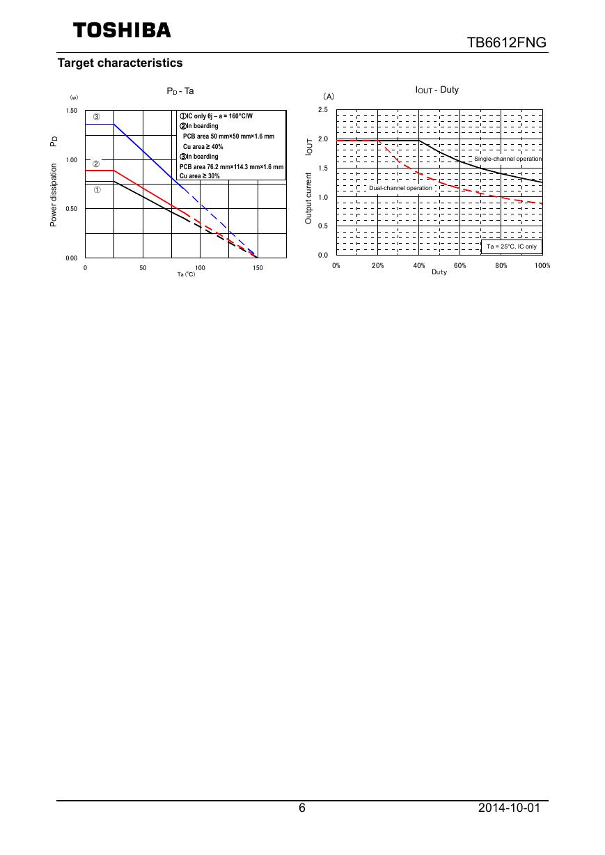
Target characteristics
0.00
0.50
①
50
TB6612FNG
Iout - Duty
IOUT - Duty
Dual-channel operation
2ch動作時
2 ch driving
Single-channel operation
1 ch driving
1ch動作時
Ta = 25°C, IC only
Ta = 25°C, IC only
Ta=25℃,IC単体
100%
PD - Ta
PD - Ta
①IC only θj – a = 160°C/W
①IC単体θj-a=160℃/W
②基板実装時
②In boarding
PCB面積 50×50×1.6mm
PCB area 50 mm×50 mm×1.6 mm
Cu箔面積≧40%
Cu area ≥ 40%
③基板実装時
③In boarding
PCB面積 76.2×114.3×1.6mm
PCB area 76.2 mm×114.3 mm×1.6 mm
Cu箔面積≧30%
Cu area ≥ 30%
(A)
2.5
T
U
O
I
t
n
e
r
r
u
c
t
u
p
t
u
O
2.0
1.5
1.0
0.5
0.0
0
100
Ta (℃)
150
0%
20%
40%
60%
80%
Duty
6
2014-10-01
�
10uF
M C U
TB6612FNG
C2
+ C1
0.1uF
10uF
+4.5 V
+4.5V
to 13.5 V
~13.5V
UVLO
STBY
Control
Logic
A
H-SW
Driver
A
TSD
Control
Logic
B
H-SW
Driver
B
VM1
AO1
AO1
AO2
AO2
PGND1
PGND1
VM2
VM3
BO1
BO1
BO2
BO2
PGND2
PGND2
24
1
2
5
6
3
4
13
14
11
12
7
8
9
10
M
M
BIN2
PWMB
GND
AIN2
Vcc
STBY
PWMA
23
17
16
15
18
BIN1
AIN1
21
22
20
19
+ C3
C4
0.1uF
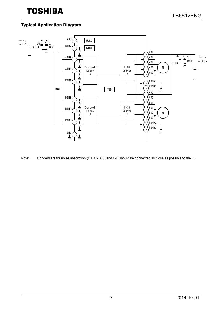
Typical Application Diagram
+2.7 V
+2.7V
to 5.5 V
~5.5V
Note:
Condensers for noise absorption (C1, C2, C3, and C4) should be connected as close as possible to the IC.
7
2014-10-01
�
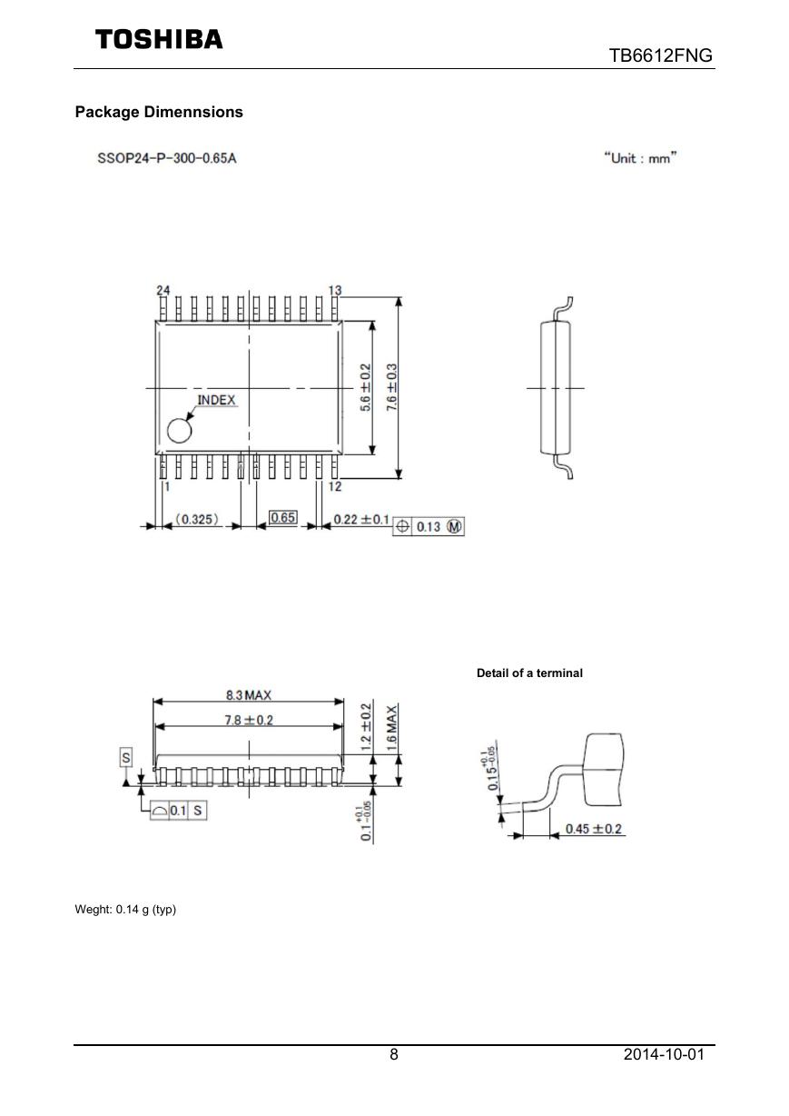
Package Dimennsions
TB6612FNG
Weght: 0.14 g (typ)
Detail of a terminal
8
2014-10-01
�


 V2版本原理图(Capacitive-Fingerprint-Reader-Schematic_V2).pdf
 摄像头工作原理.doc
 VL53L0X简要说明(En.FLVL53L00216).pdf
 原理图(DVK720-Schematic).pdf
 原理图(Pico-Clock-Green-Schdoc).pdf
 原理图(RS485-CAN-HAT-B-schematic).pdf
 File:SIM7500_SIM7600_SIM7800 Series_SSL_Application Note_V2.00.pdf
 ADS1263(Ads1262).pdf
 原理图(Open429Z-D-Schematic).pdf
 用户手册(Capacitive_Fingerprint_Reader_User_Manual_CN).pdf
 CY7C68013A(英文版)(CY7C68013A).pdf
 TechnicalReference_Dem.pdf