logo资料库

ESP32-S3数据手册(英文)(文件:Esp32-s3_datasheet_en).pdf

第1页 / 共75页
第2页 / 共75页
第3页 / 共75页
第4页 / 共75页
第5页 / 共75页
第6页 / 共75页
第7页 / 共75页
第8页 / 共75页
资料共75页,剩余部分请下载后查看
Product Overview
Features
Applications
1 ESP32-S3 Series Comparison
1.1 Nomenclature
1.2 Comparison
2 Pins
2.1 Pin Layout
2.2 Pin Overview
2.3 IO Pins
2.3.1 IO MUX and GPIO Pin Functions
2.3.2 RTC and Analog Pin Functions
2.3.3 Restrictions for GPIOs and RTC_GPIOs
2.4 Analog Pins
2.5 Power Supply
2.5.1 Power Pins
2.5.2 Power Scheme
2.5.3 Chip Power-up and Reset
2.6 Strapping Pins
2.6.1 Chip Boot Mode Control
2.6.2 VDD_SPI Voltage Control
2.6.3 ROM Messages Printing Control
2.6.4 JTAG Signal Source Control
2.7 Pin Mapping Between Chip and Flash/PSRAM
3 Functional Description
3.1 CPU and Memory
3.1.1 CPU
3.1.2 Internal Memory
3.1.3 External Flash and RAM
3.1.4 Address Mapping Structure
3.1.5 Cache
3.1.6 eFuse Controller
3.1.7 Processor Instruction Extensions
3.2 RTC and Low-Power Management
3.2.1 Power Management Unit (PMU)
3.2.2 Ultra-Low-Power Coprocessor
3.3 Analog Peripherals
3.3.1 Analog-to-Digital Converter (ADC)
3.3.2 Temperature Sensor
3.3.3 Touch Sensor
3.4 System Components
3.4.1 Reset and Clock
3.4.2 Interrupt Matrix
3.4.3 Permission Control
3.4.4 System Registers
3.4.5 GDMA Controller
3.4.6 CPU Clock
3.4.7 RTC Clock
3.4.8 Clock Glitch Detection
3.5 Digital Peripherals
3.5.1 IO MUX and GPIO Matrix
3.5.2 Serial Peripheral Interface (SPI)
3.5.3 LCD Interface
3.5.4 Camera Interface
3.5.5 UART Controller
3.5.6 I2C Interface
3.5.7 I2S Interface
3.5.8 Remote Control Peripheral
3.5.9 Pulse Count Controller
3.5.10 LED PWM Controller
3.5.11 USB 2.0 OTG Full-Speed Interface
3.5.12 USB Serial/JTAG Controller
3.5.13 Motor Control PWM (MCPWM)
3.5.14 SD/MMC Host Controller
3.5.15
3.6 Radio and Wi-Fi
3.6.1 2.4 GHz Receiver
3.6.2 2.4 GHz Transmitter
3.6.3 Clock Generator
3.6.4 Wi-Fi Radio and Baseband
3.6.5 Wi-Fi MAC
3.6.6 Networking Features
3.7 Bluetooth LE
3.7.1 Bluetooth LE Radio and PHY
3.7.2 Bluetooth LE Link Layer Controller
3.8 Timers and Watchdogs
3.8.1 General Purpose Timers
3.8.2 System Timer
3.8.3 Watchdog Timers
3.8.4 XTAL32K Watchdog Timers
3.9 Cryptography/Security Components
3.9.1 External Memory Encryption and Decryption
3.9.2 Secure Boot
3.9.3 HMAC Accelerator
3.9.4 Digital Signature
3.9.5 World Controller
3.9.6 SHA Accelerator
3.9.7 AES Accelerator
3.9.8 RSA Accelerator
3.9.9 Random Number Generator
3.10 Peripheral Pin Configurations
4 Electrical Characteristics
4.1 Absolute Maximum Ratings
4.2 Recommended Power Supply Characteristics
4.3 VDD_SPI Output Characteristics
4.4 DC Characteristics (3.3 V, 25 °C)
4.5 ADC Characteristics
4.6 Current Consumption
4.6.1 RF Current Consumption in Active Mode
4.6.2 Current Consumption in Other Modes
4.7 Reliability
4.8 Wi-Fi Radio
4.8.1 Wi-Fi RF Transmitter (TX) Specifications
4.8.2 Wi-Fi RF Receiver (RX) Specifications
4.9 Bluetooth LE Radio
4.9.1 Bluetooth LE RF Transmitter (TX) Specifications
4.9.2 Bluetooth LE RF Receiver (RX) Specifications
5 Packaging
6 Related Documentation and Resources
Appendix A – ESP32-S3 Consolidated Pin Overview
Revision History
ESP32-S3 Series Datasheet 2.4 GHz Wi-Fi + Bluetooth® LE SoC Supporting IEEE 802.11 b/g/n (2.4 GHz Wi-Fi) and Bluetooth® 5 (LE) Including: ESP32-S3 ESP32-S3FN8 ESP32-S3R2 ESP32-S3R8 ESP32-S3R8V ESP32-S3FH4R2 Version 1.6 Espressif Systems Copyright © 2023 www.espressif.com
Product Overview ESP32-S3 is a low-power MCU-based system on a chip (SoC) with integrated 2.4 GHz Wi-Fi and Bluetooth® Low Energy (Bluetooth LE). It consists of high-performance dual-core microprocessor (Xtensa® 32-bit LX7), a low power coprocessor, a Wi-Fi baseband, a Bluetooth LE baseband, RF module, and numerous peripherals. The functional block diagram of the SoC is shown below. ESP32-S3 Functional Block Diagram For more information on power consumption, see Section 3.2.1 Power Management Unit (PMU). Espressif Systems 2 ESP32-S3 Series Datasheet v1.6 Submit Documentation Feedback Espressif ESP32-S3 Wi-Fi + Bluetooth® Low Energy SoCPower consumptionNormalLow power consumption componentsWireless Digital CircuitsWi-Fi MAC Wi-Fi BasebandBluetooth LE Link ControllerBluetooth LE BasebandCPU and MemoryXtensa® Dual-core 32-bit LX7 MicroprocessorJTAGCacheROMSRAMSecurityFlash EncryptionRSARNGDigital SignatureSHAAESHMACSecure BootRTCRTC MemoryPMUULP CoprocessorPeripheralsUSB Serial/JTAGGPIOUARTTWAI®General-purpose TimersI2SI2CPulse CounterLED PWMCamera InterfaceSPI0/1RMTSPI2/3DIG ADCSystem TimersRTC GPIOTemperature SensorRTC Watchdog TimerGDMALCD InterfaceWatchdog TimersRTC ADCSDIO HostMCPWMUSB OTGeFuse ControllerTouchSensorRTC I2CRF2.4 GHz Balun + Switch2.4 GHz Receiver2.4 GHz TransmitterRF SynthesizerFast RC OscillatorExternal Main ClockPhase Lock Loop
Features Wi-Fi • IEEE 802.11 b/g/n-compliant • Supports 20 MHz, 40 MHz bandwidth in 2.4 GHz band • 1T1R mode with data rate up to 150 Mbps • Wi-Fi Multimedia (WMM) • TX/RX A-MPDU, TX/RX A-MSDU • Immediate Block ACK • Fragmentation and defragmentation • Automatic Beacon monitoring (hardware TSF) • 4 × virtual Wi-Fi interfaces • Simultaneous support for Infrastructure BSS in Station, SoftAP, or Station + SoftAP modes Note that when ESP32-S3 scans in Station mode, the SoftAP channel will change along with the Station channel • Antenna diversity • 802.11mc FTM Bluetooth • Bluetooth LE: Bluetooth 5, Bluetooth mesh • High power mode (20 dBm) • Speed: 125 Kbps, 500 Kbps, 1 Mbps, 2 Mbps • Advertising extensions • Multiple advertisement sets • Channel selection algorithm #2 • Internal co-existence mechanism between Wi-Fi and Bluetooth to share the same antenna CPU and Memory • Xtensa® dual-core 32-bit LX7 microprocessor, up to 240 MHz • CoreMark® score: – 1 core at 240 MHz: 613.86 CoreMark; 2.56 CoreMark/MHz – 2 cores at 240 MHz: 1181.60 CoreMark; 4.92 CoreMark/MHz • 128-bit data bus and SIMD commands • 384 KB ROM • 512 KB SRAM • 16 KB SRAM in RTC • SPI, Dual SPI, Quad SPI, Octal SPI, QPI and OPI interfaces that allow connection to multiple flash and external RAM • Flash controller with cache is supported • Flash in-Circuit Programming (ICP) is supported Advanced Peripheral Interfaces • 45 × programmable GPIOs • Digital interfaces: – 4 × SPI – 1 × LCD interface (8-bit ~16-bit parallel RGB, I8080 and MOTO6800), supporting conversion between RGB565, YUV422, YUV420 and YUV411 – 1 × DVP 8-bit ~16-bit camera interface – 3 × UART – 2 × I2C – 2 × I2S – 1 × RMT (TX/RX) – 1 × pulse counter – LED PWM controller, up to 8 channels – 1 × full-speed USB OTG – 1 × USB Serial/JTAG controller – 2 × MCPWM – 1 × SDIO host controller with 2 slots – General DMA controller (GDMA), with 5 transmit channels and 5 receive channels Espressif Systems 3 ESP32-S3 Series Datasheet v1.6 Submit Documentation Feedback
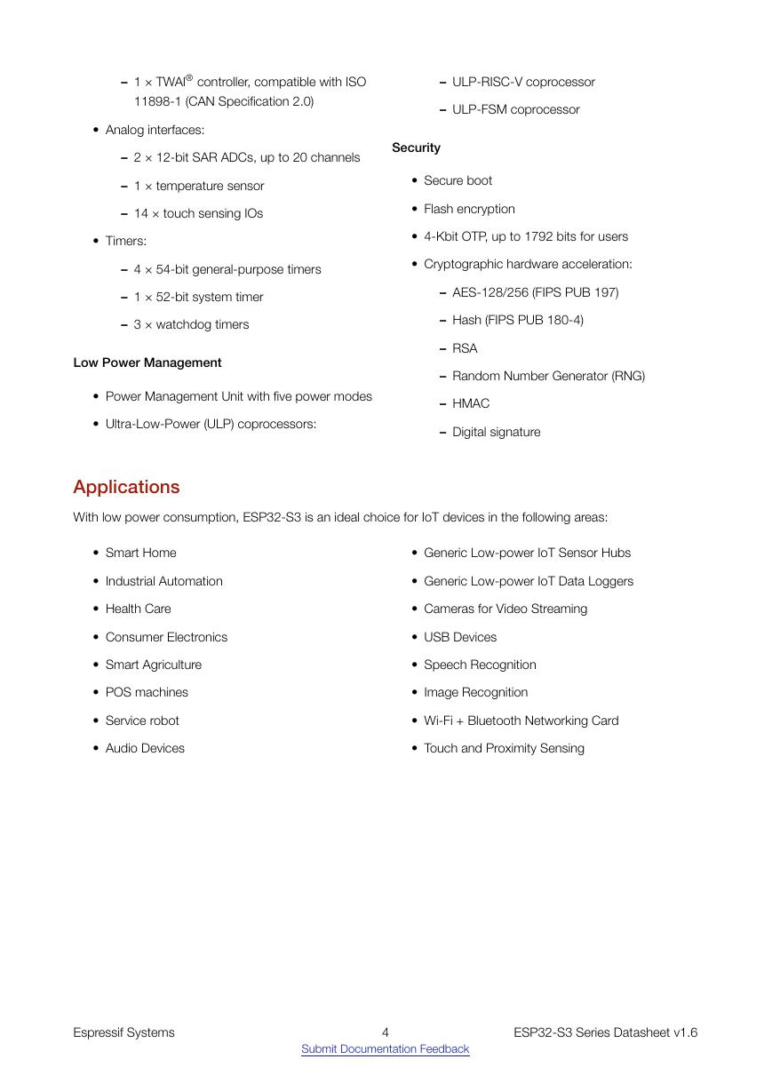
– 1 × TWAI® controller, compatible with ISO – ULP-RISC-V coprocessor 11898-1 (CAN Specification 2.0) • Analog interfaces: – ULP-FSM coprocessor – 2 × 12-bit SAR ADCs, up to 20 channels Security – 1 × temperature sensor – 14 × touch sensing IOs • Timers: – 4 × 54-bit general-purpose timers – 1 × 52-bit system timer – 3 × watchdog timers Low Power Management • Secure boot • Flash encryption • 4-Kbit OTP, up to 1792 bits for users • Cryptographic hardware acceleration: – AES-128/256 (FIPS PUB 197) – Hash (FIPS PUB 180-4) – RSA – Random Number Generator (RNG) • Power Management Unit with five power modes • Ultra-Low-Power (ULP) coprocessors: – HMAC – Digital signature Applications With low power consumption, ESP32-S3 is an ideal choice for IoT devices in the following areas: • Smart Home • Industrial Automation • Health Care • Consumer Electronics • Smart Agriculture • POS machines • Service robot • Audio Devices • Generic Low-power IoT Sensor Hubs • Generic Low-power IoT Data Loggers • Cameras for Video Streaming • USB Devices • Speech Recognition • Image Recognition • Wi-Fi + Bluetooth Networking Card • Touch and Proximity Sensing Espressif Systems 4 ESP32-S3 Series Datasheet v1.6 Submit Documentation Feedback
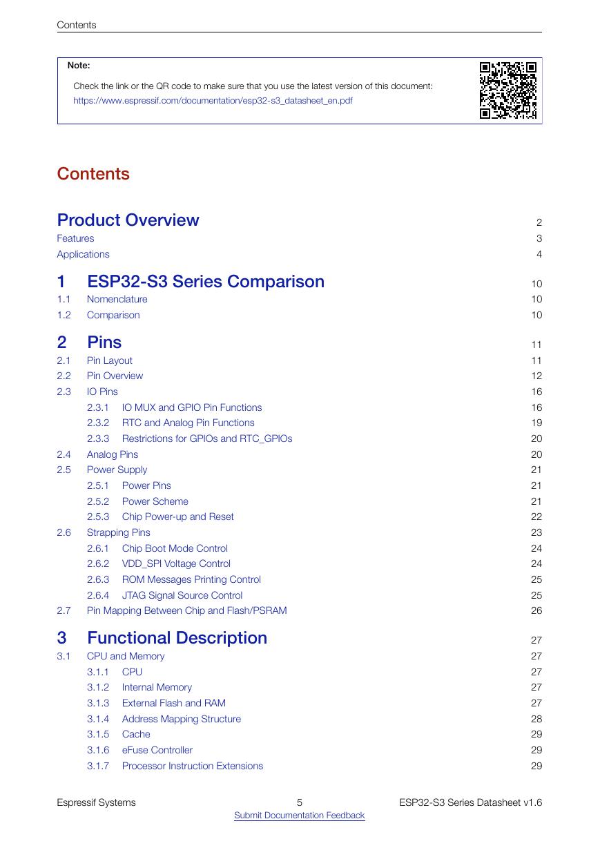
Contents Note: Check the link or the QR code to make sure that you use the latest version of this document: https://www.espressif.com/documentation/esp32-s3_datasheet_en.pdf Contents Product Overview Features Applications 1 ESP32-S3 Series Comparison 1.1 1.2 Nomenclature Comparison 2 Pins 2.1 2.2 2.3 2.4 2.5 2.6 2.7 IO MUX and GPIO Pin Functions Pin Layout Pin Overview IO Pins 2.3.1 2.3.2 RTC and Analog Pin Functions 2.3.3 Restrictions for GPIOs and RTC_GPIOs Analog Pins Power Supply 2.5.1 2.5.2 2.5.3 Chip Power-up and Reset Strapping Pins 2.6.1 Chip Boot Mode Control 2.6.2 VDD_SPI Voltage Control 2.6.3 ROM Messages Printing Control 2.6.4 Pin Mapping Between Chip and Flash/PSRAM Power Pins Power Scheme JTAG Signal Source Control 3 Functional Description 3.1 CPU and Memory 3.1.1 CPU 3.1.2 3.1.3 3.1.4 3.1.5 Cache 3.1.6 3.1.7 Internal Memory External Flash and RAM Address Mapping Structure eFuse Controller Processor Instruction Extensions 2 3 4 10 10 10 11 11 12 16 16 19 20 20 21 21 21 22 23 24 24 25 25 26 27 27 27 27 27 28 29 29 29 Espressif Systems 5 ESP32-S3 Series Datasheet v1.6 Submit Documentation Feedback
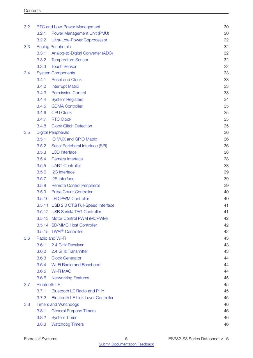
Contents 3.2 3.3 3.4 3.5 3.6 3.7 3.8 IO MUX and GPIO Matrix Serial Peripheral Interface (SPI) LCD Interface RTC and Low-Power Management Power Management Unit (PMU) 3.2.1 3.2.2 Ultra-Low-Power Coprocessor Analog Peripherals Analog-to-Digital Converter (ADC) 3.3.1 Temperature Sensor 3.3.2 3.3.3 Touch Sensor System Components 3.4.1 Reset and Clock 3.4.2 Interrupt Matrix 3.4.3 Permission Control 3.4.4 System Registers 3.4.5 GDMA Controller 3.4.6 CPU Clock 3.4.7 RTC Clock 3.4.8 Clock Glitch Detection Digital Peripherals 3.5.1 3.5.2 3.5.3 3.5.4 Camera Interface 3.5.5 UART Controller 3.5.6 3.5.7 3.5.8 Remote Control Peripheral 3.5.9 3.5.10 LED PWM Controller 3.5.11 USB 2.0 OTG Full-Speed Interface 3.5.12 USB Serial/JTAG Controller 3.5.13 Motor Control PWM (MCPWM) 3.5.14 SD/MMC Host Controller 3.5.15 TWAI® Controller Radio and Wi-Fi 3.6.1 3.6.2 3.6.3 Clock Generator 3.6.4 Wi-Fi Radio and Baseband 3.6.5 Wi-Fi MAC 3.6.6 Networking Features Bluetooth LE 3.7.1 Bluetooth LE Radio and PHY 3.7.2 Bluetooth LE Link Layer Controller Timers and Watchdogs 3.8.1 General Purpose Timers 3.8.2 3.8.3 Watchdog Timers 2.4 GHz Receiver 2.4 GHz Transmitter I2C Interface I2S Interface Pulse Count Controller 30 30 32 32 32 32 32 33 33 33 33 34 35 35 35 35 36 36 36 38 38 38 39 39 39 40 40 41 41 42 42 42 43 43 43 44 44 44 45 45 45 45 46 46 46 46 System Timer Espressif Systems 6 ESP32-S3 Series Datasheet v1.6 Submit Documentation Feedback
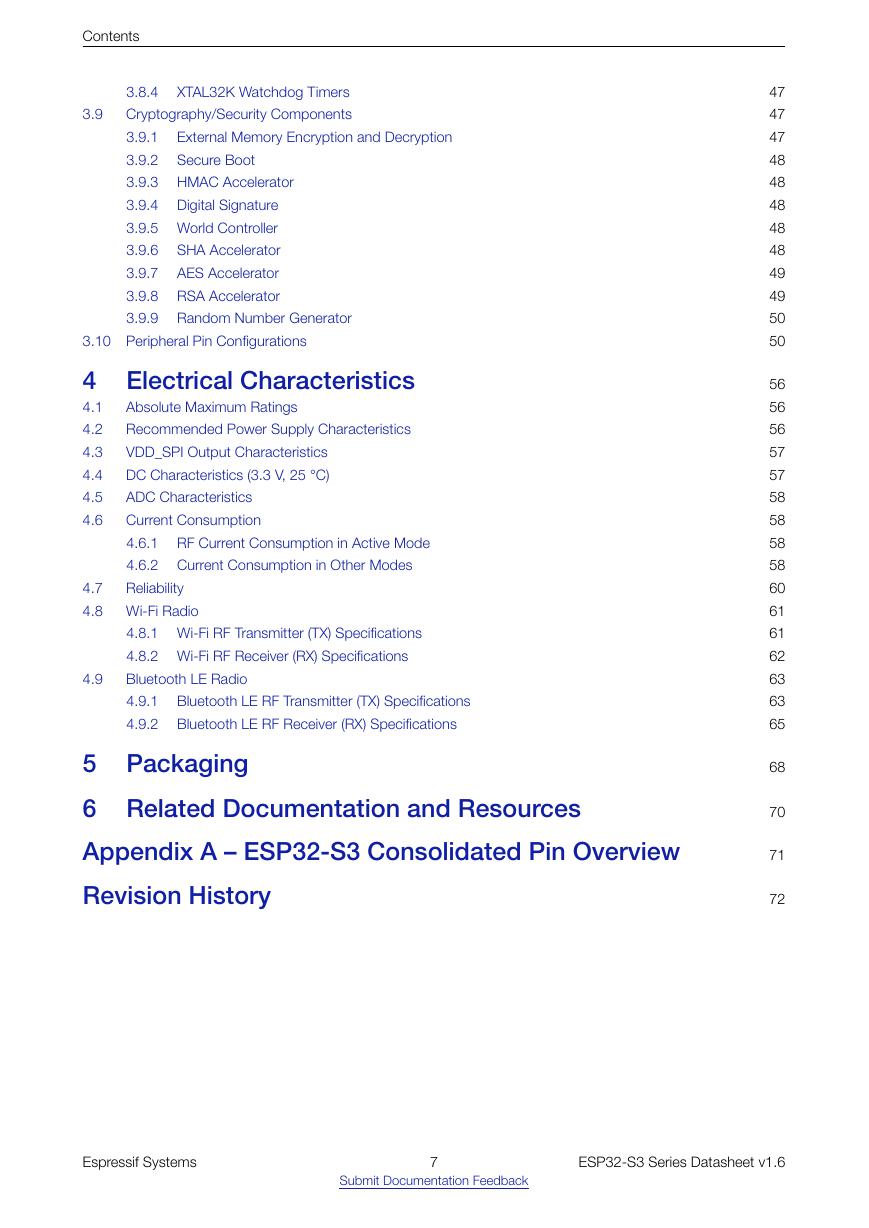
Contents 3.9 External Memory Encryption and Decryption Secure Boot 3.8.4 XTAL32K Watchdog Timers Cryptography/Security Components 3.9.1 3.9.2 3.9.3 HMAC Accelerator 3.9.4 Digital Signature 3.9.5 World Controller 3.9.6 SHA Accelerator 3.9.7 AES Accelerator 3.9.8 RSA Accelerator 3.9.9 Random Number Generator 3.10 Peripheral Pin Configurations 4 Electrical Characteristics 4.1 4.2 4.3 4.4 4.5 4.6 Absolute Maximum Ratings Recommended Power Supply Characteristics VDD_SPI Output Characteristics DC Characteristics (3.3 V, 25 °C) ADC Characteristics Current Consumption 4.6.1 RF Current Consumption in Active Mode 4.6.2 Current Consumption in Other Modes Reliability 4.7 4.8 Wi-Fi Radio 4.9 4.8.1 Wi-Fi RF Transmitter (TX) Specifications 4.8.2 Wi-Fi RF Receiver (RX) Specifications Bluetooth LE Radio 4.9.1 Bluetooth LE RF Transmitter (TX) Specifications 4.9.2 Bluetooth LE RF Receiver (RX) Specifications 5 Packaging 6 Related Documentation and Resources Appendix A – ESP32-S3 Consolidated Pin Overview Revision History 47 47 47 48 48 48 48 48 49 49 50 50 56 56 56 57 57 58 58 58 58 60 61 61 62 63 63 65 68 70 71 72 Espressif Systems 7 ESP32-S3 Series Datasheet v1.6 Submit Documentation Feedback
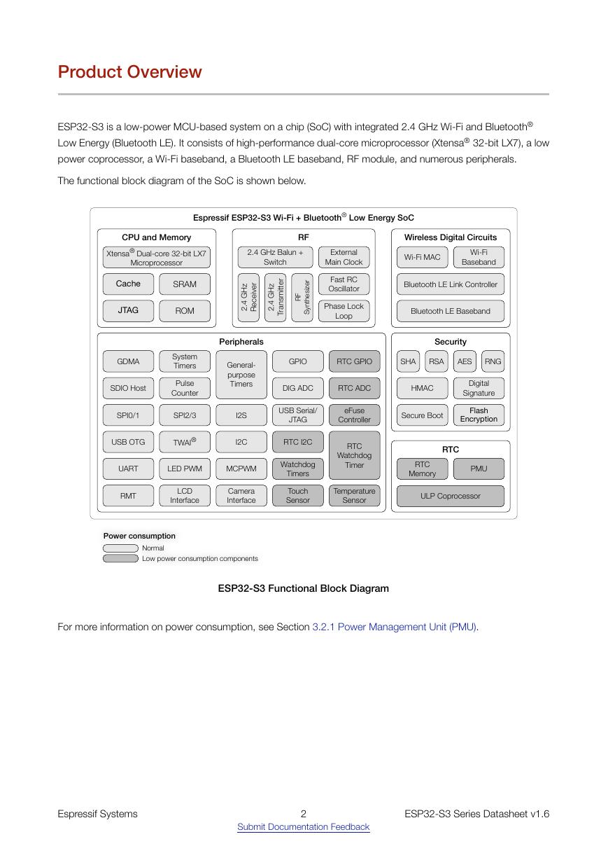
List of Tables List of Tables 1-1 ESP32-S3 Series Comparison 2-1 Pin Overview 2-2 Power-Up Glitches on Pins 2-3 IO MUX Pin Functions 2-4 RTC and Analog Functions 2-5 Analog Pins 2-6 Power Pins 2-7 Voltage Regulators 2-8 Description of Timing Parameters for Power-up and Reset 2-9 Default Configuration of Strapping Pins 2-10 Description of Timing Parameters for the Strapping Pins 2-11 Chip Boot Mode Control 2-12 VDD_SPI Voltage Control 2-13 JTAG Signal Source Control 2-14 Pin Mapping Between Chip and In-package Flash/ PSRAM 3-1 Components and Power Domains 3-2 SPI Pin Configuration 3-3 Peripheral Pin Configurations 4-1 Absolute Maximum Ratings 4-2 Recommended Power Characteristics 4-3 VDD_SPI Internal and Output Characteristics 4-4 DC Characteristics (3.3 V, 25 °C) 4-5 ADC Characteristics 4-6 Wi-Fi Current Consumption Depending on RF Modes 4-7 Current Consumption in Modem-sleep Mode 4-8 Current Consumption in Low-Power Modes 4-9 Reliability Qualifications 4-10 Wi-Fi Frequency 4-11 TX Power with Spectral Mask and EVM Meeting 802.11 Standards 4-12 TX EVM Test 4-13 RX Sensitivity 4-14 Maximum RX Level 4-15 RX Adjacent Channel Rejection 4-16 Bluetooth LE Frequency 4-17 Transmitter Characteristics - Bluetooth LE 1 Mbps 4-18 Transmitter Characteristics - Bluetooth LE 2 Mbps 4-19 Transmitter Characteristics - Bluetooth LE 125 Kbps 4-20 Transmitter Characteristics - Bluetooth LE 500 Kbps 4-21 Receiver Characteristics - Bluetooth LE 1 Mbps 4-22 Receiver Characteristics - Bluetooth LE 2 Mbps 4-23 Receiver Characteristics - Bluetooth LE 125 Kbps 4-24 Receiver Characteristics - Bluetooth LE 500 Kbps 10 13 14 17 19 20 21 21 22 23 23 24 24 25 26 31 38 50 56 56 57 57 58 58 59 59 60 61 61 61 62 62 63 63 63 64 64 64 65 66 66 67 Espressif Systems 8 ESP32-S3 Series Datasheet v1.6 Submit Documentation Feedback
分享到:
收藏