珠海智融科技有限公司
ZHUHAI ISMARTWARE TECHNOLOGY CO., LTD.
Total Solution Include PD for Bidirectional Fast Charge
Power Bank
1. General Description
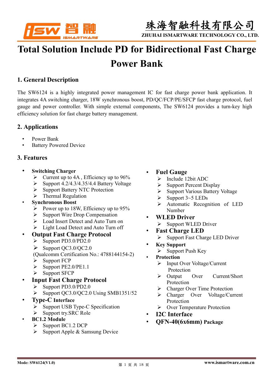
The SW6124 is a highly integrated power management IC for fast charge power bank application. It
integrates 4A switching charger, 18W synchronous boost, PD/QC/FCP/PE/SFCP fast charge protocol, fuel
gauge and power controller. With simple external components, The SW6124 provides a turn-key high
efficiency solution for fast charge battery management.
2. Applications
•
•
Power Bank
Battery Powered Device
3. Features
Switching Charger
Current up to 4A , Efficiency up to 96%
Support 4.2/4.3/4.35/4.4 Battery Voltage
Support Battery NTC Protection
Thermal Regulation
Synchronous Boost
Power up to 18W, Efficiency up to 95%
Support Wire Drop Compensation
Load Insert Detect and Auto Turn on
Light Load Detect and Auto Turn off
• Fuel Gauge
Include 12bit ADC
Support Percent Display
Support Various Battery Voltage
Support 3~5 LEDs
Automatic Recognition of LED
Number
• WLED Driver
Support WLED Driver
• Fast Charge LED
Support Fast Charge LED Driver
• Key Support
•
Support Push Key
Protection
Input Over Voltage/Current
Output
Over
Current/Short
Charger Over Time Protection
Charger Over Voltage/Current
Protection
Protection
Protection
Over Temperature Protection
I2C Interface
•
• QFN-40(6x6mm) Package
•
•
•
•
• Output Fast Charge Protocol
Support PD3.0/PD2.0
Support QC3.0/QC2.0
(Qualcomm Certification No.: 4788144154-2)
Support FCP
Support PE2.0/PE1.1
Support SFCP
Input Fast Charge Protocol
Support PD3.0/PD2.0
Support QC3.0/QC2.0 Using SMB1351/52
• Type-C Interface
Support USB Type-C Specification
Support try.SRC Role
BC1.2 Module
Support BC1.2 DCP
Support Apple & Samsung Device
Mode: SW6124(V1.0)
第 1 页 共 18 页
www.ismartware.com.cn
�
珠海智融科技有限公司
ZHUHAI ISMARTWARE TECHNOLOGY CO., LTD.
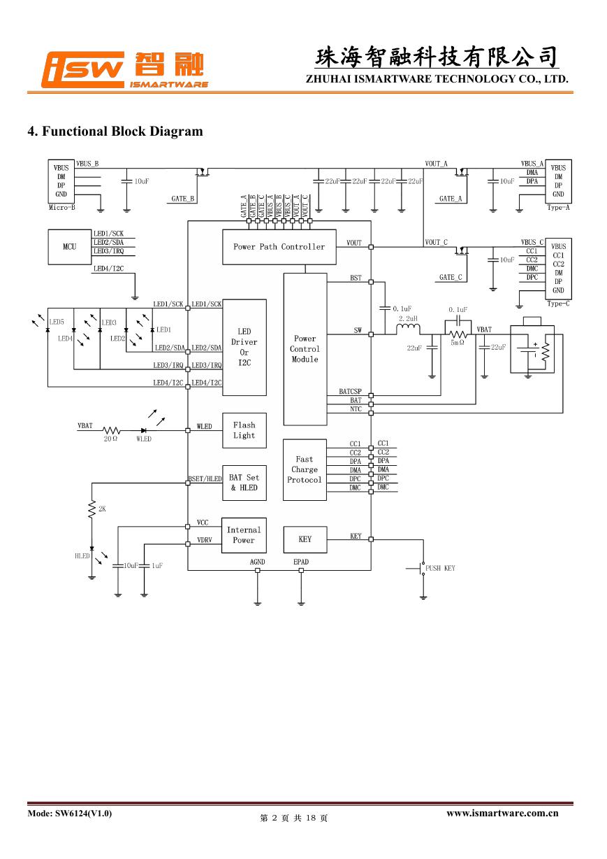
4. Functional Block Diagram
Mode: SW6124(V1.0)
第 2 页 共 18 页
www.ismartware.com.cn
�
珠海智融科技有限公司
ZHUHAI ISMARTWARE TECHNOLOGY CO., LTD.
5. Pin Configuration and Function
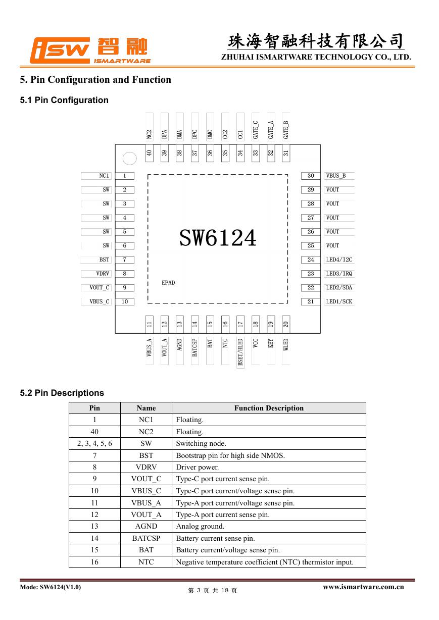
5.1 Pin Configuration
5.2 Pin Descriptions
Pin
1
40
2, 3, 4, 5, 6
7
8
9
10
11
12
13
14
15
16
Name
NC1
NC2
SW
BST
VDRV
VOUT_C
VBUS_C
VBUS_A
VOUT_A
AGND
BATCSP
BAT
NTC
Function Description
Floating.
Floating.
Switching node.
Bootstrap pin for high side NMOS.
Driver power.
Type-C port current sense pin.
Type-C port current/voltage sense pin.
Type-A port current/voltage sense pin.
Type-A port current sense pin.
Analog ground.
Battery current sense pin.
Battery current/voltage sense pin.
Negative temperature coefficient (NTC) thermistor input.
Mode: SW6124(V1.0)
第 3 页 共 18 页
www.ismartware.com.cn
�
珠海智融科技有限公司
ZHUHAI ISMARTWARE TECHNOLOGY CO., LTD.
BSET/HLED Battery voltage set and fast charge led drive.
VCC
KEY
WLED
LED1/SCK
LED2/SDA
LED3/IRQ
LED4/I2C
VOUT
VBUS_B
GATE_B
GATE_A
GATE_C
CC1
CC2
DMC
DPC
DMA
DPA
EPAD
Internal power.
Push key input.
Flash led driver.
Led1 for battery capacity indicator or i2c clock.
Led2 for battery capacity indicator or i2c data.
Led3 for battery capacity indicator or irq.
Led4 for battery capacity indicator or i2c/led set.
Boost output and charger input.
Micro-B port input.
Micro-B port power path control pin.
Type-A port power path control pin.
Type-C port power path control pin.
Type-C configure channel CC1.
Type-C configure channel CC2.
Type-C port DM pin.
Type-C port DP pin.
Type-A port DM pin.
Type-A port DP pin.
Exposed pad.
17
18
19
20
21
22
23
24
25, 26, 27,
28, 29
30
31
32
33
34
35
36
37
38
39
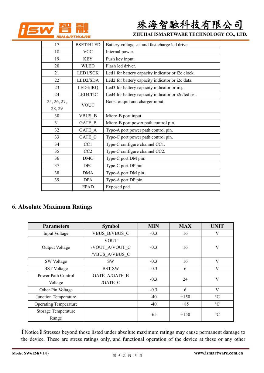
6. Absolute Maximum Ratings
Parameters
Input Voltage
Output Voltage
SW Voltage
BST Voltage
Symbol
VBUS_B/VBUS_C
VOUT
/VOUT_A/VOUT_C
/VBUS_A/VBUS_C
SW
BST-SW
Power Path Control
GATE_A/GATE_B
/GATE_C
Voltage
Other Pin Voltage
Junction Temperature
Operating Temperature
Storage Temperature
Range
MIN
-0.3
-0.3
-0.3
-0.3
-0.3
-0.3
-40
-40
-65
MAX
UNIT
16
16
16
6
24
6
+150
+85
+150
V
V
V
V
V
V
°C
°C
°C
【Notice】Stresses beyond those listed under absolute maximum ratings may cause permanent damage to
the device. These are stress ratings only, and functional operation of the device at these or any other
Mode: SW6124(V1.0)
第 4 页 共 18 页
www.ismartware.com.cn
�
珠海智融科技有限公司
ZHUHAI ISMARTWARE TECHNOLOGY CO., LTD.
conditions beyond those indicated under recommended operating conditions is not implied. Exposure to
absolute-maximum-rated conditions for extended periods my affect device reliability.
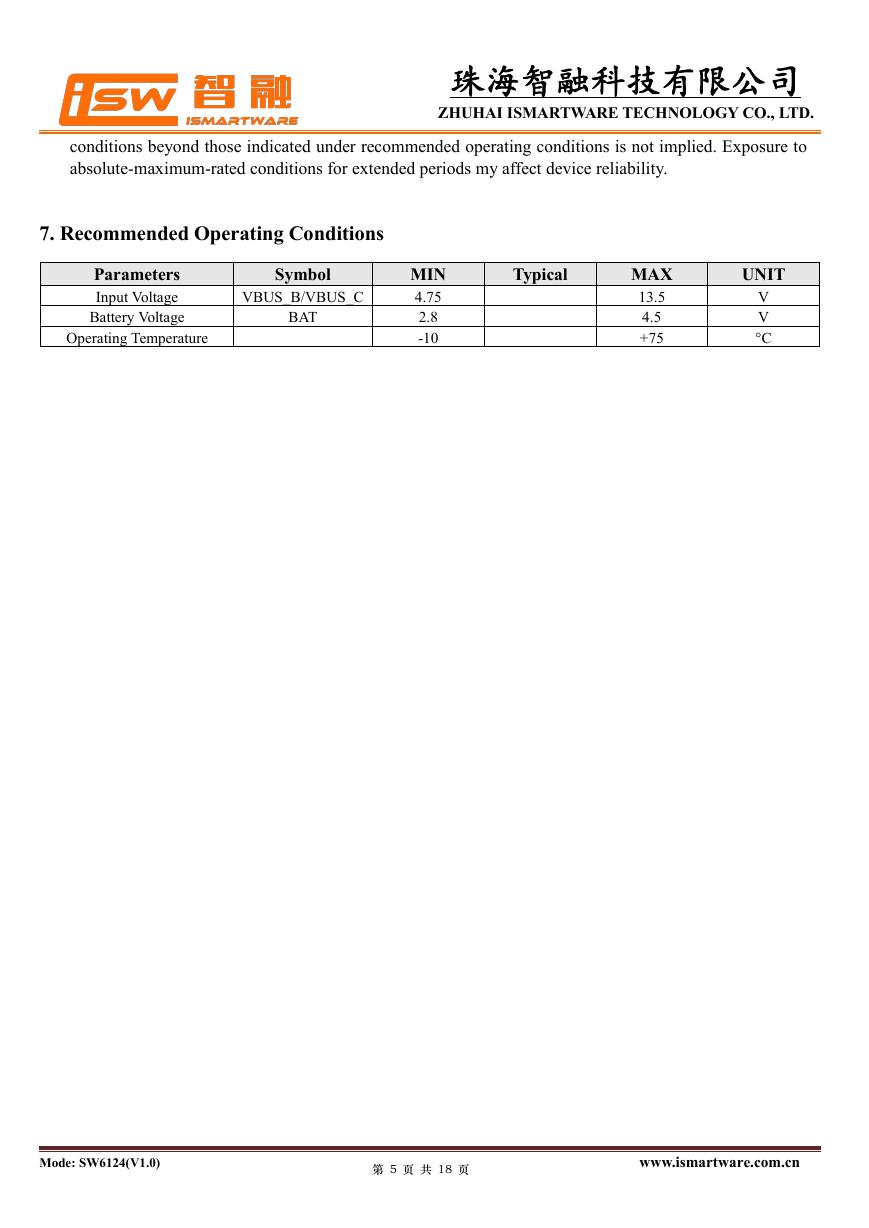
7. Recommended Operating Conditions
Parameters
Input Voltage
Battery Voltage
Operating Temperature
Symbol
VBUS_B/VBUS_C
BAT
MIN
4.75
2.8
-10
Typical
MAX
13.5
4.5
+75
UNIT
V
V
°C
Mode: SW6124(V1.0)
第 5 页 共 18 页
www.ismartware.com.cn
�
珠海智融科技有限公司
ZHUHAI ISMARTWARE TECHNOLOGY CO., LTD.
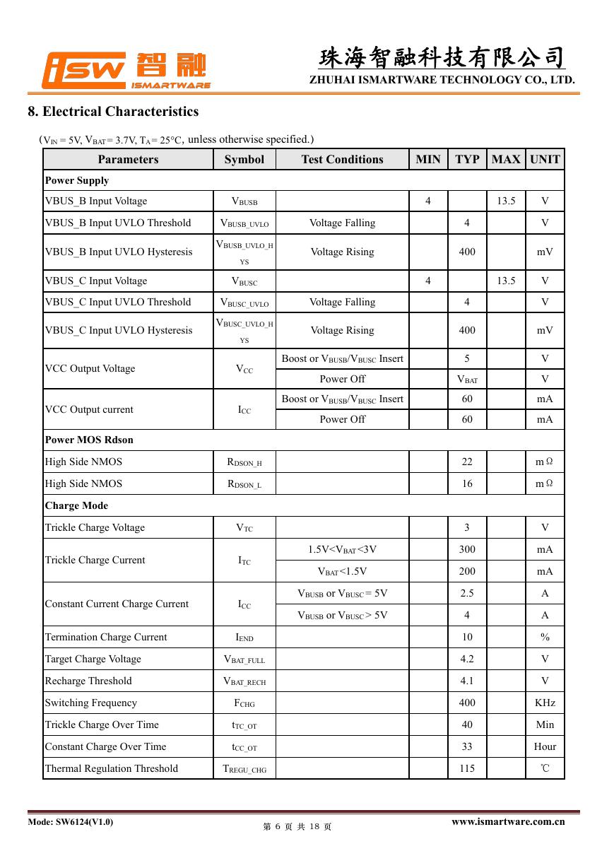
8. Electrical Characteristics
(VIN = 5V, VBAT= 3.7V, TA= 25°C, unless otherwise specified.)
Parameters
Symbol
Test Conditions
MIN TYP MAX UNIT
Power Supply
VBUS_B Input Voltage
VBUSB
VBUS_B Input UVLO Threshold
VBUSB_UVLO
Voltage Falling
Voltage Rising
Voltage Falling
Voltage Rising
Boost or VBUSB/VBUSC Insert
Power Off
Boost or VBUSB/VBUSC Insert
Power Off
1.5V 5V
VBUS_B Input UVLO Hysteresis
VBUS_C Input Voltage
VBUS_C Input UVLO Threshold
VBUS_C Input UVLO Hysteresis
VCC Output Voltage
VCC Output current
Power MOS Rdson
High Side NMOS
High Side NMOS
Charge Mode
Trickle Charge Voltage
Trickle Charge Current
Constant Current Charge Current
Termination Charge Current
Target Charge Voltage
Recharge Threshold
Switching Frequency
Trickle Charge Over Time
Constant Charge Over Time
VBUSB_UVLO_H
YS
VBUSC
VBUSC_UVLO
VBUSC_UVLO_H
YS
VCC
ICC
RDSON_H
RDSON_L
VTC
ITC
ICC
IEND
VBAT_FULL
VBAT_RECH
FCHG
tTC_OT
tCC_OT
Thermal Regulation Threshold
TREGU_CHG
4
4
4
400
4
400
5
VBAT
60
60
22
16
3
300
200
2.5
4
10
4.2
4.1
400
40
33
115
13.5
13.5
V
V
mV
V
V
mV
V
V
mA
mA
mΩ
mΩ
V
mA
mA
A
A
%
V
V
KHz
Min
Hour
℃
Mode: SW6124(V1.0)
第 6 页 共 18 页
www.ismartware.com.cn
�
珠海智融科技有限公司
ZHUHAI ISMARTWARE TECHNOLOGY CO., LTD.
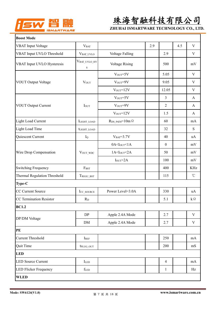
Boost Mode
VBAT Input Voltage
VBAT Input UVLO Threshold
VBAT Input UVLO Hysteresis
VOUT Output Voltage
VOUT Output Current
Light Load Current
Light Load Time
Quiescent Current
VBAT
VBAT_UVLO
VBAT_UVLO_HY
S
VOUT
IOUT
ILIGHT_LOAD
tLIGHT_LOAD
IQ
Wire Drop Compensation
VOUT_WDC
Switching Frequency
FBST
Thermal Regulation Threshold
TREGU_BST
Voltage Falling
Voltage Rising
VOUT=5V
VOUT=9V
VOUT=12V
VOUT=5V
VOUT=9V
VOUT=12V
RDS_PATH=10mΩ
VBAT=3.7V
0A2A
Type-C
CC Current Source
CC Termination Resistor
BC1.2
DP/DM Voltage
PE
Current Threshold
Quit Time
LED
LED Source Current
LED Flicker Frequency
WLED
ICC_SOURCE
Power Level=3.0A
Apple 2.4A Mode
Apple 2.4A Mode
RD
DP
DM
IREF
tPLUG_OUT
ILED
fLED
2.9
4.5
2.9
500
5.05
9.05
12.05
3
2
1.5
60
32
40
0
50
100
400
115
330
5.1
2.7
2.7
250
200
4
1
V
V
mV
V
V
V
A
A
A
mA
S
uA
mV
mV
mV
KHz
℃
uA
kΩ
V
V
mA
mS
mA
Hz
Mode: SW6124(V1.0)
第 7 页 共 18 页
www.ismartware.com.cn
�
珠海智融科技有限公司
ZHUHAI ISMARTWARE TECHNOLOGY CO., LTD.
WLED Resistor
KEY
Short Key Time
Long Key Time
I2C
Rate
Thermal Shutdown
RWLED
TSHORT
TLONG
fCLK
Thermal Shutdown Threshold
TSHDT
Temperature Rising
Thermal Shutdown Hysteresis
TSHDT_HYS
Temperature Falling
20
32
2
400
150
70
Ω
mS
S
Kbit/S
℃
℃
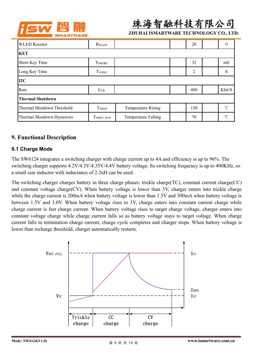
9. Functional Description
9.1 Charge Mode
The SW6124 integrates a switching charger with charge current up to 4A and efficiency is up to 96%. The
switching charger supports 4.2V/4.3V/4.35V/4.4V battery voltage. Its switching frequency is up to 400KHz, so
a small size inductor with inductance of 2.2uH can be used.
The switching charger charges battery in three charge phases: trickle charge(TC), constant current charge(CC)
and constant voltage charge(CV). When battery voltage is lower than 3V, charger enters into trickle charge
while the charge current is 200mA when battery voltage is lower than 1.5V and 300mA when battery voltage is
between 1.5V and 3.0V. When battery voltage rises to 3V, charge enters into constant current charge while
charge current is fast charge current. When battery voltage rises to target charge voltage, charger enters into
constant voltage charge while charge current falls so as battery voltage stays to target voltage. When charge
current falls to termination charge current, charge cycle completes and charger stops. When battery voltage is
lower than recharge threshold, charger automatically restarts.
Mode: SW6124(V1.0)
第 8 页 共 18 页
www.ismartware.com.cn
�


 V2版本原理图(Capacitive-Fingerprint-Reader-Schematic_V2).pdf
 摄像头工作原理.doc
 VL53L0X简要说明(En.FLVL53L00216).pdf
 原理图(DVK720-Schematic).pdf
 原理图(Pico-Clock-Green-Schdoc).pdf
 原理图(RS485-CAN-HAT-B-schematic).pdf
 File:SIM7500_SIM7600_SIM7800 Series_SSL_Application Note_V2.00.pdf
 ADS1263(Ads1262).pdf
 原理图(Open429Z-D-Schematic).pdf
 用户手册(Capacitive_Fingerprint_Reader_User_Manual_CN).pdf
 CY7C68013A(英文版)(CY7C68013A).pdf
 TechnicalReference_Dem.pdf