�
Raspberry Pi Pico Datasheet
Colophon
Copyright © 2020-2022 Raspberry Pi Ltd (formerly Raspberry Pi (Trading) Ltd.)
The documentation of the RP2040 microcontroller is licensed under a Creative Commons Attribution-NoDerivatives 4.0
International (CC BY-ND).
build-date: 2022-06-29
build-version: f9f152e-clean
About the SDK
Throughout the text "the SDK" refers to our Raspberry Pi Pico SDK. More details about the SDK can be
found in the Raspberry Pi Pico C/C++ SDK book. Source code included in the documentation is
Copyright © 2020-2022 Raspberry Pi Ltd (formerly Raspberry Pi (Trading) Ltd.) and licensed under the 3-
Clause BSD license.
Legal disclaimer notice
TECHNICAL AND RELIABILITY DATA FOR RASPBERRY PI PRODUCTS (INCLUDING DATASHEETS) AS MODIFIED FROM
TIME TO TIME (“RESOURCES”) ARE PROVIDED BY RASPBERRY PI LTD (“RPL”) "AS IS" AND ANY EXPRESS OR IMPLIED
WARRANTIES, INCLUDING, BUT NOT LIMITED TO, THE IMPLIED WARRANTIES OF MERCHANTABILITY AND FITNESS
FOR A PARTICULAR PURPOSE ARE DISCLAIMED. TO THE MAXIMUM EXTENT PERMITTED BY APPLICABLE LAW IN NO
EVENT SHALL RPL BE LIABLE FOR ANY DIRECT, INDIRECT, INCIDENTAL, SPECIAL, EXEMPLARY, OR CONSEQUENTIAL
DAMAGES (INCLUDING, BUT NOT LIMITED TO, PROCUREMENT OF SUBSTITUTE GOODS OR SERVICES; LOSS OF USE,
DATA, OR PROFITS; OR BUSINESS INTERRUPTION) HOWEVER CAUSED AND ON ANY THEORY OF LIABILITY, WHETHER
IN CONTRACT, STRICT LIABILITY, OR TORT (INCLUDING NEGLIGENCE OR OTHERWISE) ARISING IN ANY WAY OUT OF
THE USE OF THE RESOURCES, EVEN IF ADVISED OF THE POSSIBILITY OF SUCH DAMAGE.
RPL reserves the right to make any enhancements, improvements, corrections or any other modifications to the
RESOURCES or any products described in them at any time and without further notice.
The RESOURCES are intended for skilled users with suitable levels of design knowledge. Users are solely responsible for
their selection and use of the RESOURCES and any application of the products described in them. User agrees to
indemnify and hold RPL harmless against all liabilities, costs, damages or other losses arising out of their use of the
RESOURCES.
RPL grants users permission to use the RESOURCES solely in conjunction with the Raspberry Pi products. All other use
of the RESOURCES is prohibited. No licence is granted to any other RPL or other third party intellectual property right.
HIGH RISK ACTIVITIES. Raspberry Pi products are not designed, manufactured or intended for use in hazardous
environments requiring fail safe performance, such as in the operation of nuclear facilities, aircraft navigation or
communication systems, air traffic control, weapons systems or safety-critical applications (including life support
systems and other medical devices), in which the failure of the products could lead directly to death, personal injury or
severe physical or environmental damage (“High Risk Activities”). RPL specifically disclaims any express or implied
warranty of fitness for High Risk Activities and accepts no liability for use or inclusions of Raspberry Pi products in High
Risk Activities.
Raspberry Pi products are provided subject to RPL’s Standard Terms. RPL’s provision of the RESOURCES does not
expand or otherwise modify RPL’s Standard Terms including but not limited to the disclaimers and warranties
expressed in them.
Legal disclaimer notice
1
Raspberry Pi Pico Datasheet
Table of contents
Colophon . . . . . . . . . . . . . . . . . . . . . . . . . . . . . . . . . . . . . . . . . . . . . . . . . . . . . . . . . . . . . . . . . . . . . . . . . . . . . . . . . . . . . . . . . . . . . . 1
Legal disclaimer notice . . . . . . . . . . . . . . . . . . . . . . . . . . . . . . . . . . . . . . . . . . . . . . . . . . . . . . . . . . . . . . . . . . . . . . . . . . . . . . . 1
1. About Raspberry Pi Pico . . . . . . . . . . . . . . . . . . . . . . . . . . . . . . . . . . . . . . . . . . . . . . . . . . . . . . . . . . . . . . . . . . . . . . . . . . . . . . . 3
1.1. Raspberry Pi Pico design files . . . . . . . . . . . . . . . . . . . . . . . . . . . . . . . . . . . . . . . . . . . . . . . . . . . . . . . . . . . . . . . . . . . . . . 5
2. Mechanical specification . . . . . . . . . . . . . . . . . . . . . . . . . . . . . . . . . . . . . . . . . . . . . . . . . . . . . . . . . . . . . . . . . . . . . . . . . . . . . . 6
2.1. Raspberry Pi Pico pinout . . . . . . . . . . . . . . . . . . . . . . . . . . . . . . . . . . . . . . . . . . . . . . . . . . . . . . . . . . . . . . . . . . . . . . . . . . 6
2.2. Surface-mount footprint. . . . . . . . . . . . . . . . . . . . . . . . . . . . . . . . . . . . . . . . . . . . . . . . . . . . . . . . . . . . . . . . . . . . . . . . . . . 8
2.3. Recommended operating conditions . . . . . . . . . . . . . . . . . . . . . . . . . . . . . . . . . . . . . . . . . . . . . . . . . . . . . . . . . . . . . . . . 9
3. Electrical specification . . . . . . . . . . . . . . . . . . . . . . . . . . . . . . . . . . . . . . . . . . . . . . . . . . . . . . . . . . . . . . . . . . . . . . . . . . . . . . . 11
3.1. Power consumption . . . . . . . . . . . . . . . . . . . . . . . . . . . . . . . . . . . . . . . . . . . . . . . . . . . . . . . . . . . . . . . . . . . . . . . . . . . . . 11
3.1.1. Popcorn. . . . . . . . . . . . . . . . . . . . . . . . . . . . . . . . . . . . . . . . . . . . . . . . . . . . . . . . . . . . . . . . . . . . . . . . . . . . . . . . . . . 11
3.1.2. BOOTSEL mode . . . . . . . . . . . . . . . . . . . . . . . . . . . . . . . . . . . . . . . . . . . . . . . . . . . . . . . . . . . . . . . . . . . . . . . . . . . . 13
3.1.3. DORMANT mode . . . . . . . . . . . . . . . . . . . . . . . . . . . . . . . . . . . . . . . . . . . . . . . . . . . . . . . . . . . . . . . . . . . . . . . . . . . 14
3.1.4. SLEEP mode . . . . . . . . . . . . . . . . . . . . . . . . . . . . . . . . . . . . . . . . . . . . . . . . . . . . . . . . . . . . . . . . . . . . . . . . . . . . . . . 15
4. Applications information. . . . . . . . . . . . . . . . . . . . . . . . . . . . . . . . . . . . . . . . . . . . . . . . . . . . . . . . . . . . . . . . . . . . . . . . . . . . . . 17
4.1. Programming the flash. . . . . . . . . . . . . . . . . . . . . . . . . . . . . . . . . . . . . . . . . . . . . . . . . . . . . . . . . . . . . . . . . . . . . . . . . . . 17
4.2. General purpose I/O . . . . . . . . . . . . . . . . . . . . . . . . . . . . . . . . . . . . . . . . . . . . . . . . . . . . . . . . . . . . . . . . . . . . . . . . . . . . . 17
4.3. Using the ADC . . . . . . . . . . . . . . . . . . . . . . . . . . . . . . . . . . . . . . . . . . . . . . . . . . . . . . . . . . . . . . . . . . . . . . . . . . . . . . . . . . 17
4.4. Powerchain . . . . . . . . . . . . . . . . . . . . . . . . . . . . . . . . . . . . . . . . . . . . . . . . . . . . . . . . . . . . . . . . . . . . . . . . . . . . . . . . . . . . 18
4.5. Powering Pico . . . . . . . . . . . . . . . . . . . . . . . . . . . . . . . . . . . . . . . . . . . . . . . . . . . . . . . . . . . . . . . . . . . . . . . . . . . . . . . . . . 19
4.6. Using a battery charger . . . . . . . . . . . . . . . . . . . . . . . . . . . . . . . . . . . . . . . . . . . . . . . . . . . . . . . . . . . . . . . . . . . . . . . . . . 20
4.7. USB . . . . . . . . . . . . . . . . . . . . . . . . . . . . . . . . . . . . . . . . . . . . . . . . . . . . . . . . . . . . . . . . . . . . . . . . . . . . . . . . . . . . . . . . . . . 21
4.8. Debugging . . . . . . . . . . . . . . . . . . . . . . . . . . . . . . . . . . . . . . . . . . . . . . . . . . . . . . . . . . . . . . . . . . . . . . . . . . . . . . . . . . . . . 21
Appendix A: Availability . . . . . . . . . . . . . . . . . . . . . . . . . . . . . . . . . . . . . . . . . . . . . . . . . . . . . . . . . . . . . . . . . . . . . . . . . . . . . . . . . 22
Support . . . . . . . . . . . . . . . . . . . . . . . . . . . . . . . . . . . . . . . . . . . . . . . . . . . . . . . . . . . . . . . . . . . . . . . . . . . . . . . . . . . . . . . . . . . 22
Ordering code . . . . . . . . . . . . . . . . . . . . . . . . . . . . . . . . . . . . . . . . . . . . . . . . . . . . . . . . . . . . . . . . . . . . . . . . . . . . . . . . . . . . . . 22
Appendix B: Pico schematic . . . . . . . . . . . . . . . . . . . . . . . . . . . . . . . . . . . . . . . . . . . . . . . . . . . . . . . . . . . . . . . . . . . . . . . . . . . . . 23
Appendix C: Pico component locations. . . . . . . . . . . . . . . . . . . . . . . . . . . . . . . . . . . . . . . . . . . . . . . . . . . . . . . . . . . . . . . . . . . . 26
Appendix D: Documentation release history. . . . . . . . . . . . . . . . . . . . . . . . . . . . . . . . . . . . . . . . . . . . . . . . . . . . . . . . . . . . . . . . 27
Table of contents
2
�
Raspberry Pi Pico Datasheet
Chapter 1. About Raspberry Pi Pico
Raspberry Pi Pico is a microcontroller board based on the Raspberry Pi RP2040 microcontroller chip.
Figure 1. The
Raspberry Pi Pico
Rev3 board.
Raspberry Pi Pico has been designed to be a low cost yet flexible development platform for RP2040, with the following
key features:
• RP2040 microcontroller with 2MB Flash
• Micro-USB B port for power and data (and for reprogramming the Flash)
• 40 pin 21×51 'DIP' style 1mm thick PCB with 0.1" through-hole pins also with edge castellations
◦ Exposes 26 multi-function 3.3V General Purpose I/O (GPIO)
◦ 23 GPIO are digital-only and 3 are ADC capable
◦ Can be surface mounted as a module
• 3-pin ARM Serial Wire Debug (SWD) port
• Simple yet highly flexible power supply architecture
◦ Various options for easily powering the unit from micro-USB, external supplies or batteries
• High quality, low cost, high availability
• Comprehensive SDK, software examples and documentation
For full details of the RP2040 microcontroller please see the RP2040 Datasheet, however the headline features are:
• Dual-core cortex M0+ at up to 133MHz
◦ On-chip PLL allows variable core frequency
• 264kB multi-bank high performance SRAM
• External Quad-SPI Flash with eXecute In Place (XIP) and 16kB on-chip cache
• High performance full-crossbar bus fabric
Chapter 1. About Raspberry Pi Pico
3
�
Raspberry Pi Pico Datasheet
• On-board USB1.1 (device or host)
• 30 multi-function General Purpose IO (4 can be used for ADC)
◦ 1.8-3.3V IO Voltage (NOTE Pico IO voltage is fixed at 3.3V)
• 12-bit 500ksps Analogue to Digital Converter (ADC)
• Various digital peripherals
◦ 2 × UART, 2 × I2C, 2 × SPI, 16 × PWM channels
◦ 1 × Timer with 4 alarms, 1 × Real Time Counter
• 2 × Programmable IO (PIO) blocks, 8 state machines total
◦ Flexible, user-programmable high-speed IO
◦ Can emulate interfaces such as SD Card and VGA
Pico provides minimal (yet flexible) external circuitry to support the RP2040 chip: flash (Winbond W25Q16JV), crystal,
power supplies and decoupling, and USB connector. The majority of the RP2040 microcontroller pins are brought to the
user IO pins on the left and right edge of the board. Four RP2040 IO are used for internal functions - driving an LED, on-
board Switched Mode Power Supply (SMPS) power control and sensing the system voltages.
Pico has been designed to use either soldered 0.1" pin-headers (it is one 0.1" pitch wider than a standard 40-pin DIP
package) or can be used as a surface mountable 'module', as the user IO pins are also castellated. There are SMT pads
underneath the USB connector and BOOTSEL button, which allow these signals to be accessed if used as a reflow-
soldered SMT module.
Figure 2. The pinout of
the Raspberry Pi Pico
Rev3 board
Pico uses an on-board buck-boost SMPS which is able to generate the required 3.3V (to power RP2040 and external
circuitry) from a wide range of input voltages (~1.8 to 5.5V). This allows significant flexibility in powering the unit from
various sources such as a single Lithium-Ion cell, or 3 AA cells in series. Battery chargers can also be very easily
integrated with the Pico powerchain.
Reprogramming the Pico Flash can be done using USB (simply drag and drop a file onto the Pico which appears as a
mass storage device), or the standard Serial Wire Debug (SWD) port can reset the system and load and run code
without any button presses. The SWD port can also be used to interactively debug code running on the RP2040.
Chapter 1. About Raspberry Pi Pico
4
�
Raspberry Pi Pico Datasheet
Getting started with Raspberry Pi Pico
The Getting started with Raspberry Pi Pico book walks through loading programs onto the board, and
shows how to install the C/C++ SDK and build the example C programs. See the Raspberry Pi Pico
Python SDK book to get started with MicroPython, which is the fastest way to get code running on Pico.
1.1. Raspberry Pi Pico design files
The source design files, including the schematic and PCB layout, are made available openly, with no limitations.
Schematic
The full schematic is reproduced in Appendix B. The schematic is also distributed alongside the
layout files here.
Layout
The full CAD files, including PCB layout, can be found here. Note that Raspberry Pi Pico was
designed in Cadence Allegro PCB Editor, and opening in other PCB CAD packages requires an
import script or plugin.
STEP 3D
A STEP 3D model of Raspberry Pi Pico, for 3D visualisation and fit check of designs which include
Raspberry Pi Pico as a module, can be found here.
Fritzing
A Fritzing part for use in e.g. breadboard layouts can be found here.
Permission to use, copy, modify, and/or distribute this design for any purpose with or without fee is hereby granted.
THE DESIGN IS PROVIDED "AS IS" AND THE AUTHOR DISCLAIMS ALL WARRANTIES WITH REGARD TO THIS DESIGN
INCLUDING ALL IMPLIED WARRANTIES OF MERCHANTABILITY AND FITNESS. IN NO EVENT SHALL THE AUTHOR BE
LIABLE FOR ANY SPECIAL, DIRECT, INDIRECT, OR CONSEQUENTIAL DAMAGES OR ANY DAMAGES WHATSOEVER
RESULTING FROM LOSS OF USE, DATA OR PROFITS, WHETHER IN AN ACTION OF CONTRACT, NEGLIGENCE OR
OTHER TORTIOUS ACTION, ARISING OUT OF OR IN CONNECTION WITH THE USE OR PERFORMANCE OF THIS DESIGN.
Other RP2040 design resources
The Hardware design with RP2040 book walks through designing a minimal RP2040-based 2-layer
board (KiCad files here), and another board which uses Raspberry Pi Pico as a module (KiCad files
here), explaining the relevant design considerations along the way, at both the schematic and layout
level.
1.1. Raspberry Pi Pico design files
5
�
Raspberry Pi Pico Datasheet
Chapter 2. Mechanical specification
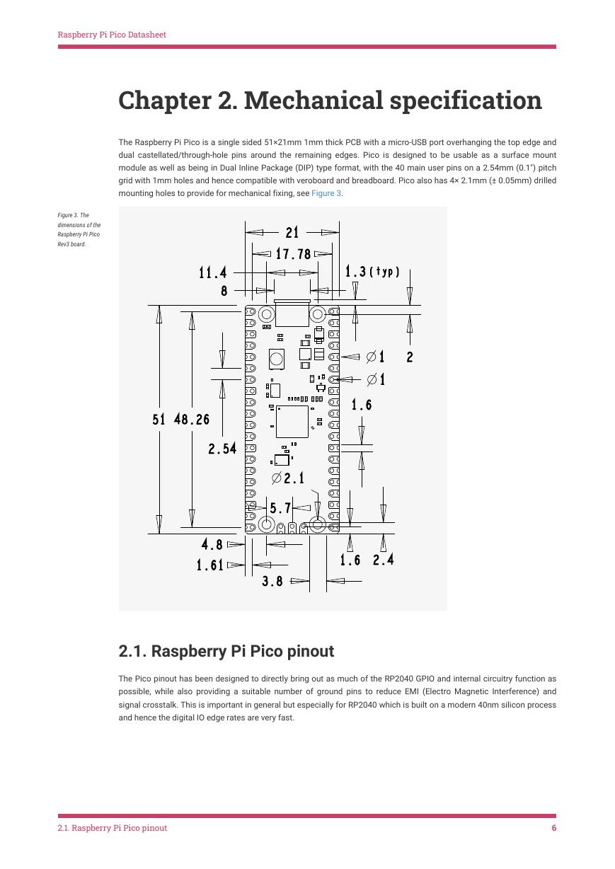
The Raspberry Pi Pico is a single sided 51×21mm 1mm thick PCB with a micro-USB port overhanging the top edge and
dual castellated/through-hole pins around the remaining edges. Pico is designed to be usable as a surface mount
module as well as being in Dual Inline Package (DIP) type format, with the 40 main user pins on a 2.54mm (0.1") pitch
grid with 1mm holes and hence compatible with veroboard and breadboard. Pico also has 4× 2.1mm (± 0.05mm) drilled
mounting holes to provide for mechanical fixing, see Figure 3.
Figure 3. The
dimensions of the
Raspberry Pi Pico
Rev3 board.
2.1. Raspberry Pi Pico pinout
The Pico pinout has been designed to directly bring out as much of the RP2040 GPIO and internal circuitry function as
possible, while also providing a suitable number of ground pins to reduce EMI (Electro Magnetic Interference) and
signal crosstalk. This is important in general but especially for RP2040 which is built on a modern 40nm silicon process
and hence the digital IO edge rates are very fast.
2.1. Raspberry Pi Pico pinout
6
�
Raspberry Pi Pico Datasheet
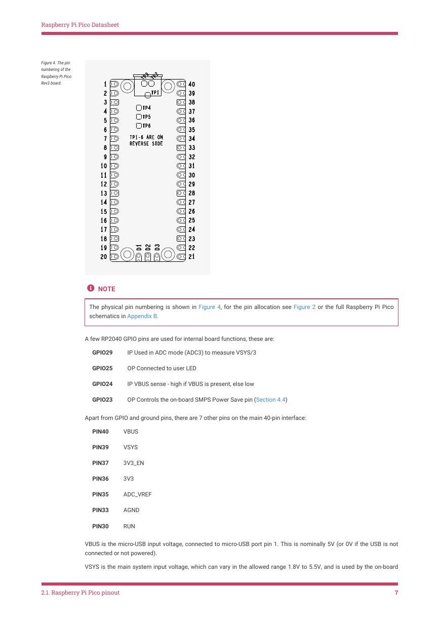
Figure 4. The pin
numbering of the
Raspberry Pi Pico
Rev3 board.
NOTE
The physical pin numbering is shown in Figure 4, for the pin allocation see Figure 2 or the full Raspberry Pi Pico
schematics in Appendix B.
A few RP2040 GPIO pins are used for internal board functions, these are:
GPIO29
IP Used in ADC mode (ADC3) to measure VSYS/3
GPIO25
OP Connected to user LED
GPIO24
IP VBUS sense - high if VBUS is present, else low
GPIO23
OP Controls the on-board SMPS Power Save pin (Section 4.4)
Apart from GPIO and ground pins, there are 7 other pins on the main 40-pin interface:
PIN40
VBUS
PIN39
VSYS
PIN37
3V3_EN
PIN36
3V3
PIN35
ADC_VREF
PIN33
AGND
PIN30
RUN
VBUS is the micro-USB input voltage, connected to micro-USB port pin 1. This is nominally 5V (or 0V if the USB is not
connected or not powered).
VSYS is the main system input voltage, which can vary in the allowed range 1.8V to 5.5V, and is used by the on-board
2.1. Raspberry Pi Pico pinout
7
�




 V2版本原理图(Capacitive-Fingerprint-Reader-Schematic_V2).pdf
 摄像头工作原理.doc
 VL53L0X简要说明(En.FLVL53L00216).pdf
 原理图(DVK720-Schematic).pdf
 原理图(Pico-Clock-Green-Schdoc).pdf
 原理图(RS485-CAN-HAT-B-schematic).pdf
 File:SIM7500_SIM7600_SIM7800 Series_SSL_Application Note_V2.00.pdf
 ADS1263(Ads1262).pdf
 原理图(Open429Z-D-Schematic).pdf
 用户手册(Capacitive_Fingerprint_Reader_User_Manual_CN).pdf
 CY7C68013A(英文版)(CY7C68013A).pdf
 TechnicalReference_Dem.pdf