ScanPartner 15C
Image Scanner
User's Manual
Version 1.0
(Doc. No. 250-0062-E)
FCC Radio Frequency Interference Statement
This equipment has been tested and found to comply with the limits for a
class B digital device, pursuant to Part 15 of the FCC rules. These limits are
designed to provide reasonable protection against harmful interference in a
residential installation. This equipment generates, uses, and can radiate
radio frequency energy and, if not installed and used in accordance with
the instruction manual, may cause harmful interference to radio
communication. However, there is no guarantee that interference will not
occur in a particular installation. If this equipment does cause harmful
interference to radio or television reception, which can be determined by
turning the equipment off and on, the user is encouraged to try to correct
the interference by one or more of the following measures:
* Reorient or relocate the receiving antenna.
* Increase the separation between the equipment and receiver.
* Connect the equipment into an outlet on a circuit different from that to which
the receiver is connected.
* Consult the dealer or an experienced radio/TV technician for help.
CAUTION: Any changes or modifications not expressly approved by the
manufacture of this device could void the user's authority to operate the
equipment.
ii
Table of Contents
1. INTRODUCTION...........................................................................................1-1
2. INSTALLATION AND CONNECTIONS...................................................2-1
2.1 SHIPPING BRACKET ......................................................................................2-1
2.1.1 Removing the Shipping Bracket (refer to figures 2-1 and 2-2) ....2-1
2.1.2 Refitting the Shipping Bracket: ......................................................2-3
2.2 SCSI INTERFACE DEVICE ID ........................................................................2-3
2.3 ADF PAPER CHUTE (FIGURE 2-4)................................................................2-5
2.4 ADF OUTPUT TRAY (FIGURE 2-5) ...............................................................2-6
2.5 DOCUMENT LOADING .................................................................................2-7
2.6 ADF SCANNING ..........................................................................................2-8
2.7 CONNECTING THE CABLE ............................................................................2-9
3. MAINTENANCE ............................................................................................3-1
3.1 CLEANING THE ADF....................................................................................3-1
3.2 CLEANING THE GLASS .................................................................................3-3
3.3 REPLACING THE SNAP-IN PAD MODULE .......................................................3-4
4. TROUBLESHOOTING..................................................................................4-1
4.1 QUESTION AND ANSWER .............................................................................4-1
4.2 PAPER JAM IN THE ADF...............................................................................4-3
5. SPECIFICATIONS..........................................................................................5-1
5.1 SCANPARTNER 15C SPECIFICATIONS...........................................................5-2
iii
1. INTRODUCTION
Congratulations on your purchase of Fujitsu ScanPartner 15C scanner.
Before you install and operate the new scanner, please take a few minutes to
read through this manual. It provides you with the proper instructions on
how to unpack, install, operate and maintain the scanner.
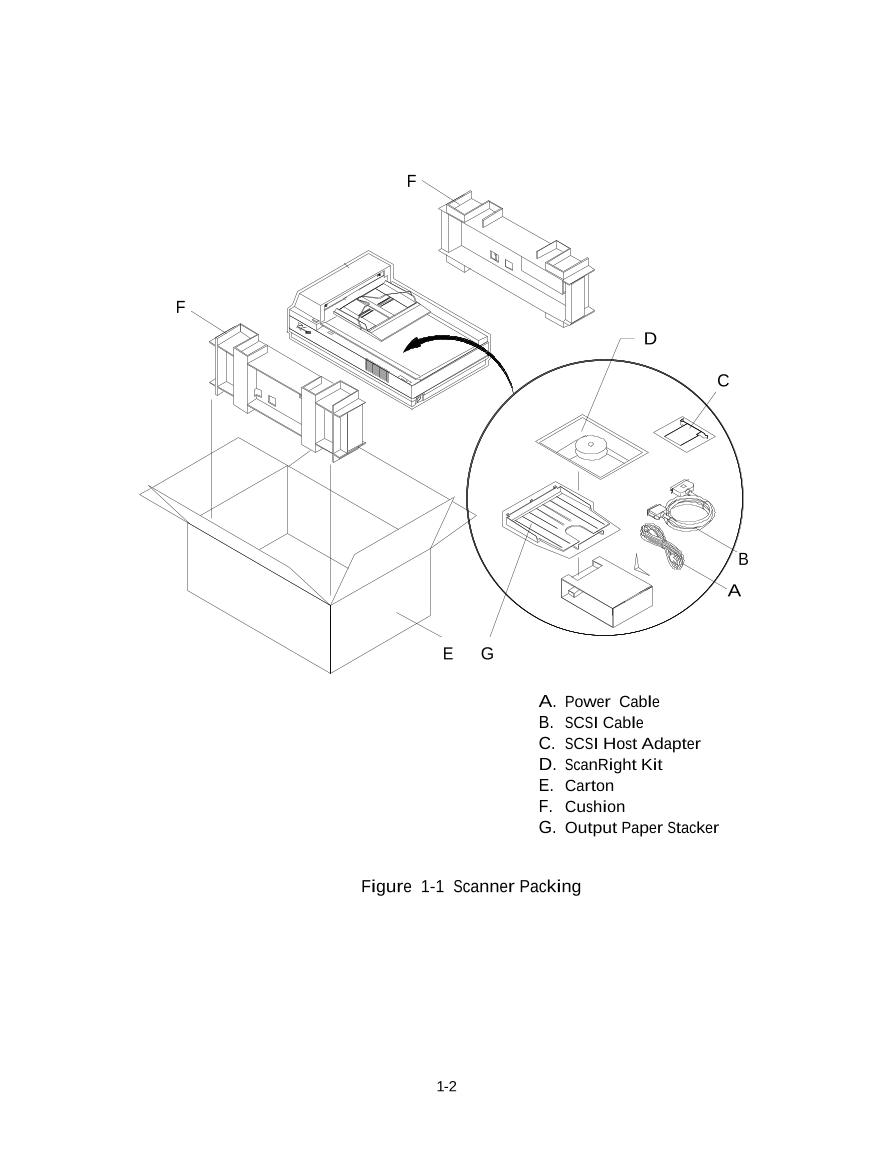
Figure 1-1 shows how the scanner is packed. You can check all items
against your “checklist”, included with your scanner.
1-1
F
F
D
C
B
A
E G G
A. Power Cable
B. SCSI Cable
C. SCSI Host Adapter
D. ScanRight Kit
E. Carton
F. Cushion
G. Output Paper Stacker
Figure 1-1 Scanner Packing
1-2
2. INSTALLATION AND CONNECTIONS
Please unpack the scanner carefully, and check the contents against the checklist. If any
items are missing or damaged, please contact your authorized local dealer
immediately.
Precautions
v Keep the scanner out of direct sunlight. Direct exposure to the sun or excessive
heat may cause damage to the unit.
v Do not install the scanner in a humid or dusty place.
v Be sure to use the proper AC power source.
v Place the scanner securely on an even, flat surface. Tilted or uneven surfaces may
cause mechanical or paper-feeding problems.
v Retain the scanner box and packing materials for shipping purposes.
2.1 Shipping Bracket
The scanner has a bracket that locks the carrier mechanism for transportation
purposes. This bracket must be put into the use position before using the scanner.
If the power is turned on before the bracket has been removed the PAPER JAM light
will turn on. Before proceeding, turn the power off, disconnect all cables and follow
the instructions below to remove the shipping bracket.
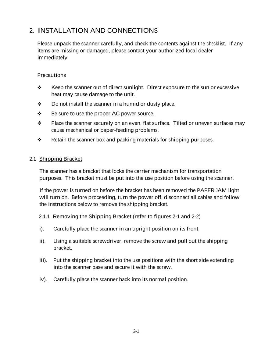
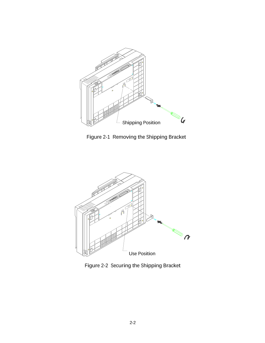
2.1.1 Removing the Shipping Bracket (refer to figures 2-1 and 2-2)
i). Carefully place the scanner in an upright position on its front.
ii). Using a suitable screwdriver, remove the screw and pull out the shipping
bracket.
iii). Put the shipping bracket into the use positions with the short side extending
into the scanner base and secure it with the screw.
iv). Carefully place the scanner back into its normal position.
2-1
Shipping Position
Figure 2-1 Removing the Shipping Bracket
Use Position
Figure 2-2 Securing the Shipping Bracket
2-2
2.1.2 Refitting the Shipping Bracket:
Whenever you need to move the scanner to a new location it is advisable to refit
the shipping bracket to avoid causing damage to the scanners’ internal
mechanism. Please follow the instructions below to refit the shipping bracket.
i). Turn off the scanner power at the power on/off switch.
ii). Open the document cover.
iii). Turn off the scanner.
Note: For steps (iv) to (vi) please refer to figure 2-1 and 2-2
iv). Carefully place the scanner in an upright position on its front side.
v). Use a suitable screwdriver to remove the screw holding the shipping
bracket in the use position.
vi). Put the shipping bracket into the shipping position, with the long side
extending into the scanner base. Secure it with the screw.
vii). Carefully place the scanner back into its normal position.
2.2 SCSI Interface Device ID
When you have several devices on a SCSI chain, you may need to adjust
the SCSI ID selector setting located on the back of the scanner. This setting assigns a
specific "device ID" to the scanner. If the assignment conflicts with an existing SCSI
device, please select a new ID. (See Figure 2-3)
Note: The factory setting for scanner is ID 6. Usually, ID 0 is assigned to an internal
hard disk drive, and ID 7, to SCSI adapter or host. ID 8 and 9 are not in actual
use.
Using a suitable tool, turn the selector switch until the arrow points to the desired ID
number.
2-3



 V2版本原理图(Capacitive-Fingerprint-Reader-Schematic_V2).pdf
 摄像头工作原理.doc
 VL53L0X简要说明(En.FLVL53L00216).pdf
 原理图(DVK720-Schematic).pdf
 原理图(Pico-Clock-Green-Schdoc).pdf
 原理图(RS485-CAN-HAT-B-schematic).pdf
 File:SIM7500_SIM7600_SIM7800 Series_SSL_Application Note_V2.00.pdf
 ADS1263(Ads1262).pdf
 原理图(Open429Z-D-Schematic).pdf
 用户手册(Capacitive_Fingerprint_Reader_User_Manual_CN).pdf
 CY7C68013A(英文版)(CY7C68013A).pdf
 TechnicalReference_Dem.pdf