Product
Document
Published by
ams OSRAM Group
�
General Description
TCS3408
ALS/Color Sensor with Selective
Flicker Detection
The TCS3408 features ambient light and color (RGB) sensing, as
well as flicker detection which suppresses cross-coupling from
940nm IR, if generated by adjacent circuits (e.g. TOF). The device
comes in a low-profile and small footprint, L2.5mm x W2.0mm
x H0.5mm package.
The Ambient Light and Color Sensing function provides five
concurrent ambient light sensing channels: Red, Green, Blue,
Clear, and Wideband. The RGB and Clear channels have a UV/IR
blocking filter. This architecture accurately measures ambient
light and enables the calculation of illuminance, chromaticity,
and color temperature to manage display appearance.
The device integrates direct detection of 50Hz or 60Hz ambient
light flicker. Flicker detection is executed in parallel with
ambient light and color sensing and has independent gain
configuration. The flicker detection engine can also buffer data
for calculating other flicker frequencies externally.
Ordering Information and Content Guide appear at end of
datasheet.
ams Datasheet
[v1-01] 2021-Jul-28
Page 1
Document Feedback
�
TCS3408 − General Description
Key Benefits & Features
The benefits and features of TCS3408 are listed below:
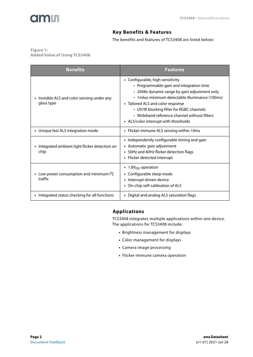
Figure 1:
Added Value of Using TCS3408
Benefits
Features
• Invisible ALS and color sensing under any
glass type
• Configurable, high sensitivity
• Programmable gain and integration time
• 2048x dynamic range by gain adjustment only
• 1mlux minimum detectable illuminance (100ms)
• Tailored ALS and color response
• UV/IR blocking filter for RGBC channels
• Wideband reference channel without filters
• ALS/color interrupt with thresholds
• Unique fast ALS integration mode
• Flicker-immune ALS sensing within 10ms
• Integrated ambient light flicker detection on
chip
• Low power consumption and minimum I²C
traffic
• Independently configurable timing and gain
• Automatic gain adjustment
• 50Hz and 60Hz flicker detection flags
• Flicker detected interrupt
• 1.8VDD operation
• Configurable sleep mode
• Interrupt-driven device
• On-chip self-calibration of ALS
• Integrated status checking for all functions
• Digital and analog ALS saturation flags
Applications
TCS3408 integrates multiple applications within one device.
The applications for TCS3408 include:
• Brightness management for displays
• Color management for displays
• Camera image processing
• Flicker-immune camera operation
Page 2
Document Feedback
ams Datasheet
[v1-01] 2021-Jul-28
�
TCS3408 − General Description
Figure 2:
Functional Blocks of TCS3408
Block Diagram
The functional blocks of this device are shown below:
C
R
G
B
W
F1
F2
l
r
e
x
e
p
i
t
l
u
M
ALS Engine
Clear (C)
Color (RGB)
Wideband (W)
Flicker (F1, F2)
VDD
PGND
VSS
TCS3408
A
D
CA
D
CA
D
CA
D
CA
A
D
D
C
C
s
6
A
L
S
Registers
+
-
+ Limit
INPUT
- Limit
Interrupt Flags
Digital Core
OSCILLATOR
I2C
SCL
SDA
INT
ams Datasheet
[v1-01] 2021-Jul-28
Page 3
Document Feedback
�
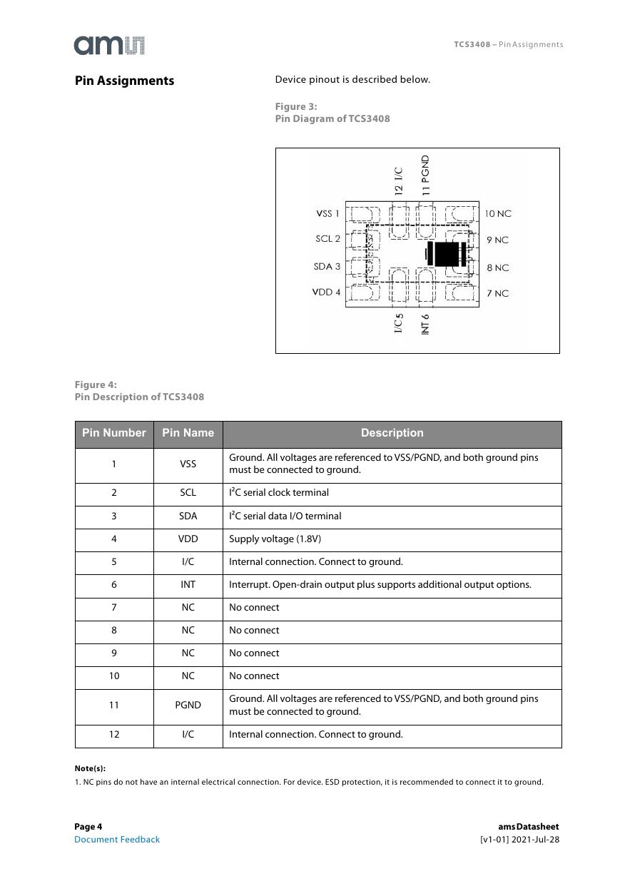
Pin Assignments
Device pinout is described below.
TCS3408 − Pin Assignments
Figure 3:
Pin Diagram of TCS3408
C
/
I
C
/
I
Figure 4:
Pin Description of TCS3408
Pin Number
Pin Name
Description
1
2
3
4
5
6
7
8
9
10
11
12
VSS
SCL
SDA
VDD
I/C
INT
NC
NC
NC
NC
Ground. All voltages are referenced to VSS/PGND, and both ground pins
must be connected to ground.
I²C serial clock terminal
I²C serial data I/O terminal
Supply voltage (1.8V)
Internal connection. Connect to ground.
Interrupt. Open-drain output plus supports additional output options.
No connect
No connect
No connect
No connect
PGND
Ground. All voltages are referenced to VSS/PGND, and both ground pins
must be connected to ground.
I/C
Internal connection. Connect to ground.
Note(s):
1. NC pins do not have an internal electrical connection. For device. ESD protection, it is recommended to connect it to ground.
Page 4
Document Feedback
ams Datasheet
[v1-01] 2021-Jul-28
�
TCS3408 − Absolute Maximum Ratings
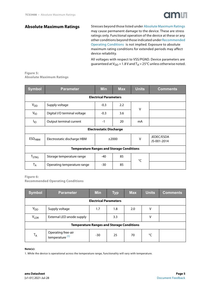
Absolute Maximum Ratings
Stresses beyond those listed under Absolute Maximum Ratings
may cause permanent damage to the device. These are stress
ratings only. Functional operation of the device at these or any
other conditions beyond those indicated under Recommended
Operating Conditions is not implied. Exposure to absolute
maximum rating conditions for extended periods may affect
device reliability.
All voltages with respect to VSS/PGND. Device parameters are
guaranteed at VDD = 1.8 V and TA = 25°C unless otherwise noted.
Figure 5:
Absolute Maximum Ratings
Symbol
Parameter
Min
Max
Units
Comments
Electrical Parameters
VDD
VIO
IIO
Supply voltage
Digital I/O terminal voltage
Output terminal current
-0.3
-0.3
-1
2.2
3.6
20
Electrostatic Discharge
ESDHBM
Electrostatic discharge HBM
±2000
V
mA
V
Temperature Ranges and Storage Conditions
TSTRG
TA
Storage temperature range
Operating temperature range
-40
-30
85
85
°C
Figure 6:
Recommended Operating Conditions
JEDEC/ESDA
JS-001-2014
Symbol
Parameter
Min
Typ
Max
Units
Comments
Electrical Parameters
VDD
VLDR
TA
Supply voltage
1.7
External LED anode supply
2.0
1.8
3.3
Temperature Ranges and Storage Conditions
Operating free-air
temperature (1)
-30
25
70
V
V
°C
Note(s):
1. While the device is operational across the temperature range, functionality will vary with temperature.
ams Datasheet
[v1-01] 2021-Jul-28
Page 5
Document Feedback
�
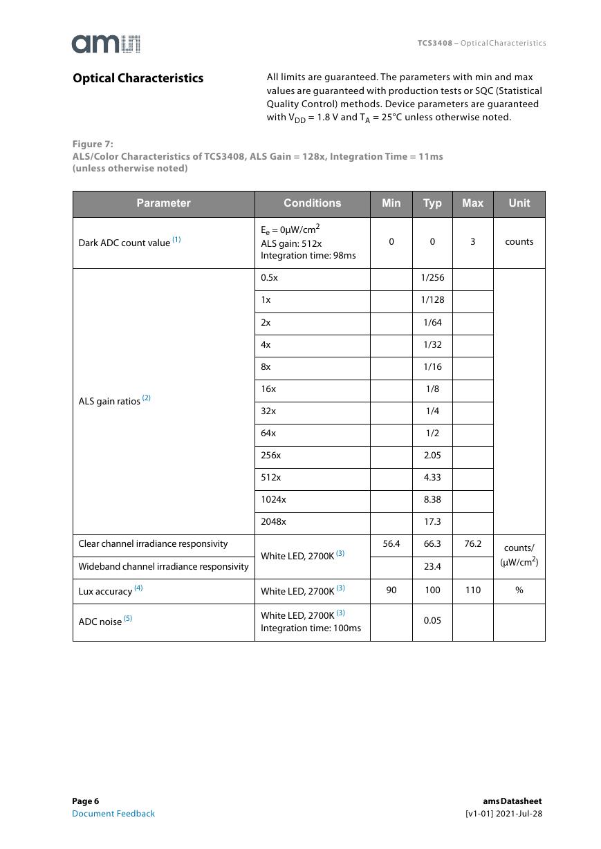
Optical Characteristics
TCS3408 − Optical Characteristics
All limits are guaranteed. The parameters with min and max
values are guaranteed with production tests or SQC (Statistical
Quality Control) methods. Device parameters are guaranteed
with VDD = 1.8 V and TA = 25°C unless otherwise noted.
Figure 7:
ALS/Color Characteristics of TCS3408, ALS Gain = 128x, Integration Time = 11ms
(unless otherwise noted)
Parameter
Conditions
Min
Typ
Max
Unit
Dark ADC count value (1)
Ee = 0μW/cm2
ALS gain: 512x
Integration time: 98ms
0
0
3
counts
ALS gain ratios (2)
0.5x
1x
2x
4x
8x
16x
32x
64x
256x
512x
1024x
2048x
Clear channel irradiance responsivity
Wideband channel irradiance responsivity
White LED, 2700K (3)
56.4
Lux accuracy (4)
ADC noise (5)
White LED, 2700K (3)
90
White LED, 2700K (3)
Integration time: 100ms
1/256
1/128
1/64
1/32
1/16
1/8
1/4
1/2
2.05
4.33
8.38
17.3
66.3
23.4
100
0.05
76.2
counts/
(μW/cm2)
110
%
Page 6
Document Feedback
ams Datasheet
[v1-01] 2021-Jul-28
�
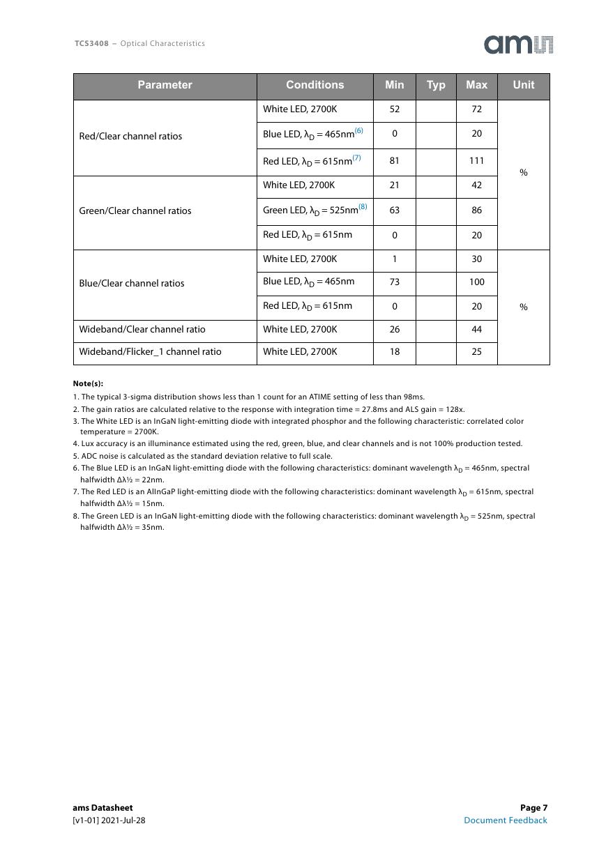
TCS3408 − Optical Characteristics
Parameter
Conditions
Min
Typ
Max
Unit
Red/Clear channel ratios
Green/Clear channel ratios
Blue/Clear channel ratios
White LED, 2700K
Blue LED, λD = 465nm(6)
Red LED, λD = 615nm(7)
White LED, 2700K
Green LED, λD = 525nm(8)
Red LED, λD = 615nm
White LED, 2700K
Blue LED, λD = 465nm
Red LED, λD = 615nm
Wideband/Clear channel ratio
White LED, 2700K
Wideband/Flicker_1 channel ratio
White LED, 2700K
52
0
81
21
63
0
1
73
0
26
18
72
20
111
42
86
20
30
100
20
44
25
%
%
Note(s):
1. The typical 3-sigma distribution shows less than 1 count for an ATIME setting of less than 98ms.
2. The gain ratios are calculated relative to the response with integration time = 27.8ms and ALS gain = 128x.
3. The White LED is an InGaN light-emitting diode with integrated phosphor and the following characteristic: correlated color
temperature = 2700K.
4. Lux accuracy is an illuminance estimated using the red, green, blue, and clear channels and is not 100% production tested.
5. ADC noise is calculated as the standard deviation relative to full scale.
6. The Blue LED is an InGaN light-emitting diode with the following characteristics: dominant wavelength λD = 465nm, spectral
halfwidth Δλ½ = 22nm.
7. The Red LED is an AlInGaP light-emitting diode with the following characteristics: dominant wavelength λD = 615nm, spectral
halfwidth Δλ½ = 15nm.
8. The Green LED is an InGaN light-emitting diode with the following characteristics: dominant wavelength λD = 525nm, spectral
halfwidth Δλ½ = 35nm.
ams Datasheet
[v1-01] 2021-Jul-28
Page 7
Document Feedback
�




 V2版本原理图(Capacitive-Fingerprint-Reader-Schematic_V2).pdf
 摄像头工作原理.doc
 VL53L0X简要说明(En.FLVL53L00216).pdf
 原理图(DVK720-Schematic).pdf
 原理图(Pico-Clock-Green-Schdoc).pdf
 原理图(RS485-CAN-HAT-B-schematic).pdf
 File:SIM7500_SIM7600_SIM7800 Series_SSL_Application Note_V2.00.pdf
 ADS1263(Ads1262).pdf
 原理图(Open429Z-D-Schematic).pdf
 用户手册(Capacitive_Fingerprint_Reader_User_Manual_CN).pdf
 CY7C68013A(英文版)(CY7C68013A).pdf
 TechnicalReference_Dem.pdf