ST7735S
132RGB x 162dot 262K Color with Frame Memory
Single-Chip TFT Controller/Driver
Datasheet
Version 1.1
2011/11
Sitronix Technology Corp. reserves the right to change the contents in this
document without prior notice.
�
ST7735S
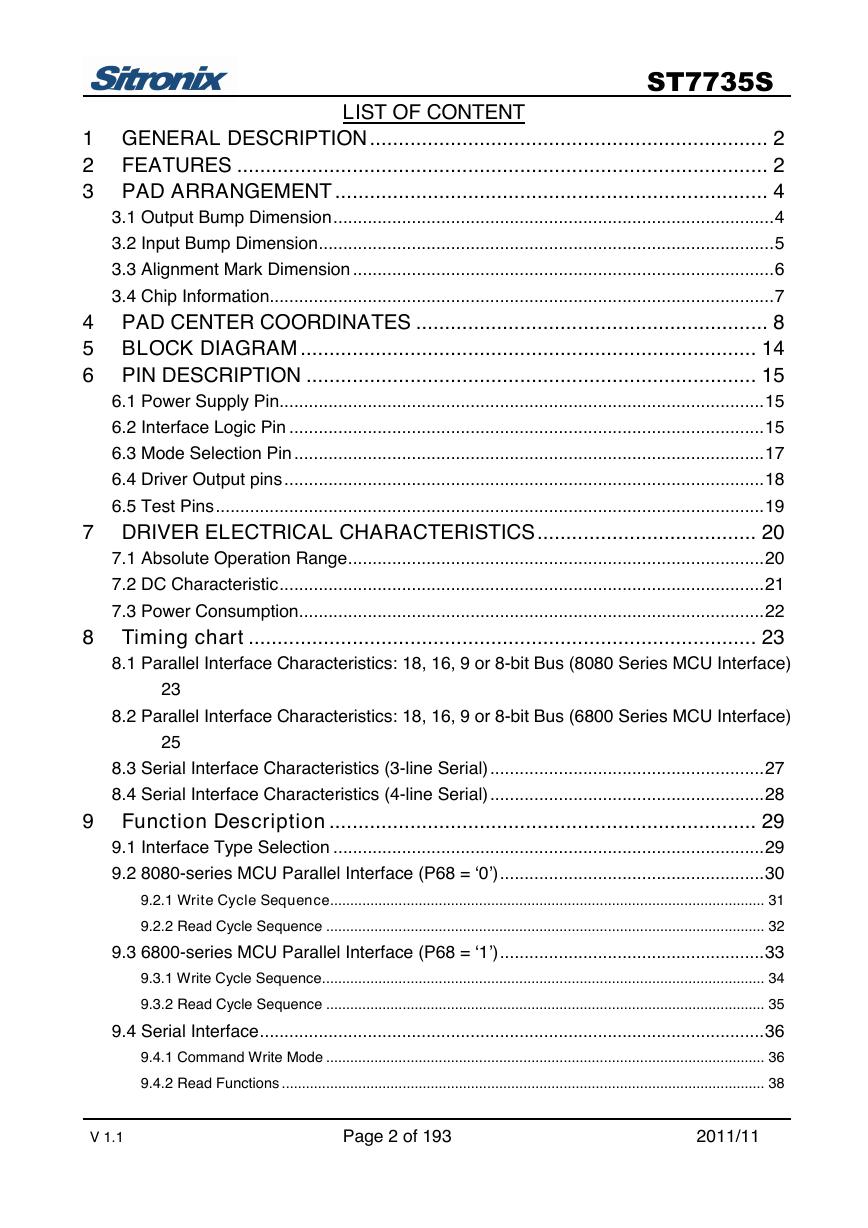
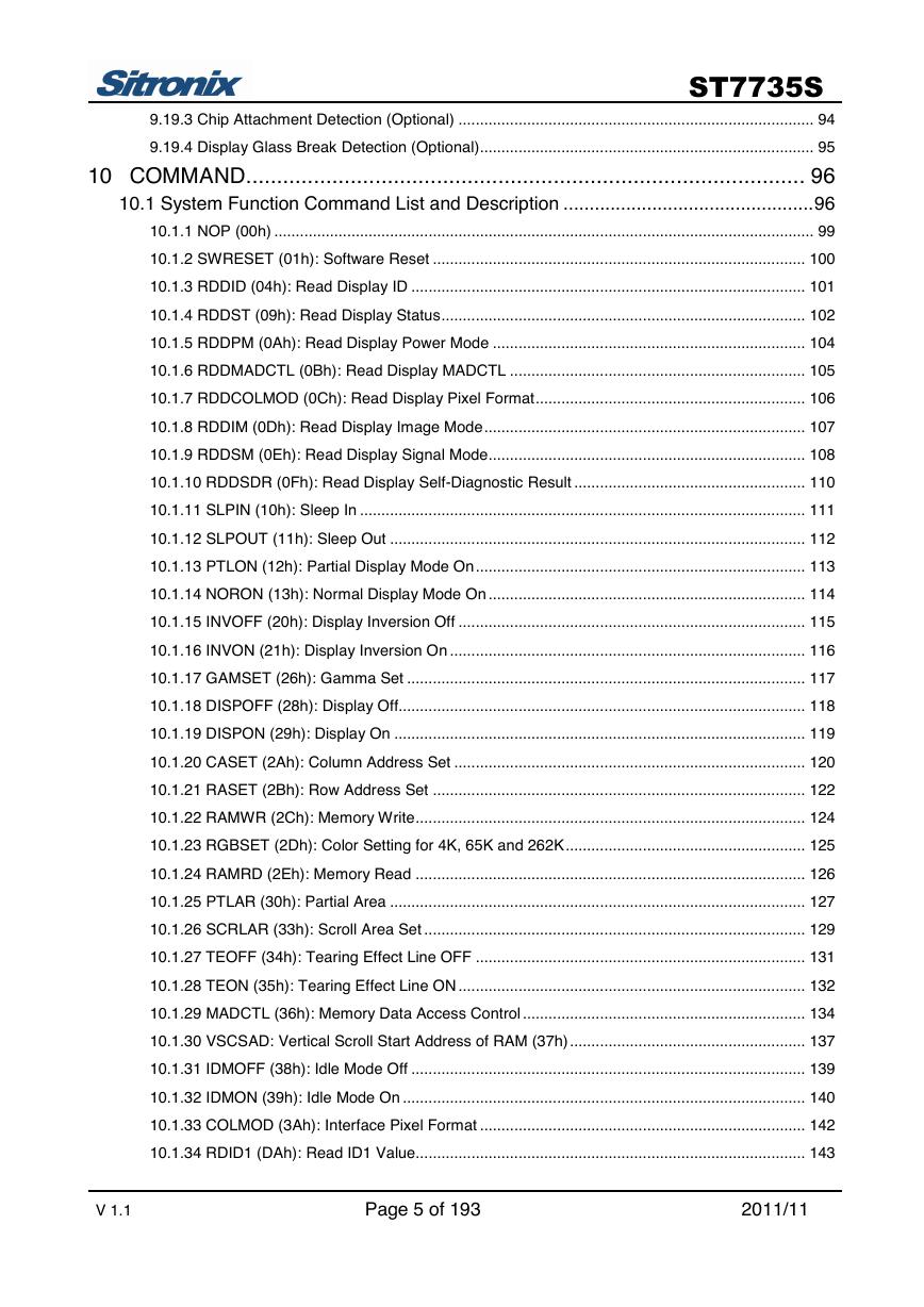
LIST OF CONTENT
1 GENERAL DESCRIPTION..................................................................... 2
2 FEATURES ............................................................................................ 2
3 PAD ARRANGEMENT ........................................................................... 4
3.1 Output Bump Dimension..........................................................................................4
3.2 Input Bump Dimension.............................................................................................5
3.3 Alignment Mark Dimension ......................................................................................6
3.4 Chip Information.......................................................................................................7
4 PAD CENTER COORDINATES ............................................................. 8
5 BLOCK DIAGRAM ............................................................................... 14
6 PIN DESCRIPTION .............................................................................. 15
6.1 Power Supply Pin...................................................................................................15
6.2 Interface Logic Pin .................................................................................................15
6.3 Mode Selection Pin ................................................................................................17
6.4 Driver Output pins..................................................................................................18
6.5 Test Pins................................................................................................................19
7 DRIVER ELECTRICAL CHARACTERISTICS...................................... 20
7.1 Absolute Operation Range.....................................................................................20
7.2 DC Characteristic...................................................................................................21
7.3 Power Consumption...............................................................................................22
8 Timing chart ........................................................................................ 23
8.1 Parallel Interface Characteristics: 18, 16, 9 or 8-bit Bus (8080 Series MCU Interface)
8.2 Parallel Interface Characteristics: 18, 16, 9 or 8-bit Bus (6800 Series MCU Interface)
8.3 Serial Interface Characteristics (3-line Serial)........................................................27
8.4 Serial Interface Characteristics (4-line Serial)........................................................28
9 Function Description .......................................................................... 29
9.1 Interface Type Selection ........................................................................................29
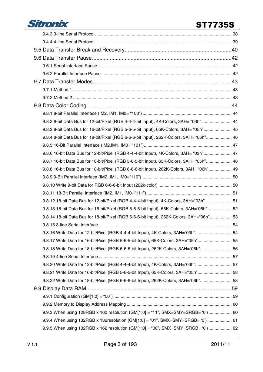
9.2 8080-series MCU Parallel Interface (P68 = ‘0’)......................................................30
9.2.1 Write Cycle Sequence............................................................................................................ 31
9.2.2 Read Cycle Sequence ............................................................................................................. 32
9.3 6800-series MCU Parallel Interface (P68 = ‘1’)......................................................33
9.3.1 Write Cycle Sequence.............................................................................................................. 34
9.3.2 Read Cycle Sequence ............................................................................................................. 35
9.4 Serial Interface.......................................................................................................36
9.4.1 Command Write Mode ............................................................................................................. 36
9.4.2 Read Functions ........................................................................................................................ 38
23
25
V 1.1 Page 2 of 193 2011/11
�
ST7735S
9.4.3 3-line Serial Protocol ................................................................................................................ 38
9.4.4 4-line Serial Protocol ................................................................................................................ 39
9.5 Data Transfer Break and Recovery........................................................................40
9.6 Data Transfer Pause..............................................................................................42
9.6.1 Serial Interface Pause.............................................................................................................. 42
9.6.2 Parallel Interface Pause ........................................................................................................... 42
9.7 Data Transfer Modes .............................................................................................43
9.7.1 Method 1 .................................................................................................................................. 43
9.7.2 Method 2 .................................................................................................................................. 43
9.8 Data Color Coding .................................................................................................44
9.8.1 8-bit Parallel Interface (IM2, IM1, IM0= “100”) ......................................................................... 44
9.8.2 8-bit Data Bus for 12-bit/Pixel (RGB 4-4-4-bit Input), 4K-Colors, 3AH= “03h”......................... 44
9.8.3 8-bit Data Bus for 16-bit/Pixel (RGB 5-6-5-bit Input), 65K-Colors, 3AH= “05h”....................... 45
9.8.4 8-bit Data Bus for 18-bit/Pixel (RGB 6-6-6-bit Input), 262K-Colors, 3AH= “06h”..................... 46
9.8.5 16-Bit Parallel Interface (IM2,IM1, IM0= “101”)........................................................................ 47
9.8.6 16-bit Data Bus for 12-bit/Pixel (RGB 4-4-4-bit Input), 4K-Colors, 3AH= “03h”....................... 47
9.8.7 16-bit Data Bus for 16-bit/Pixel (RGB 5-6-5-bit Input), 65K-Colors, 3AH= “05h”..................... 48
9.8.8 16-bit Data Bus for 18-bit/Pixel (RGB 6-6-6-bit Input), 262K-Colors, 3AH= “06h”................... 49
9.8.9 9-Bit Parallel Interface (IM2, IM1, IM0=“110”).......................................................................... 50
9.8.10 Write 9-bit Data for RGB 6-6-6-bit Input (262k-color) ............................................................ 50
9.8.11 18-Bit Parallel Interface (IM2, IM1, IM0=“111”)...................................................................... 51
9.8.12 18-bit Data Bus for 12-bit/Pixel (RGB 4-4-4-bit Input), 4K-Colors, 3AH=“03h”...................... 51
9.8.13 18-bit Data Bus for 16-bit/Pixel (RGB 5-6-5-bit Input), 65K-Colors, 3AH=“05h”.................... 52
9.8.14 18-bit Data Bus for 18-bit/Pixel (RGB 6-6-6-bit Input), 262K-Colors, 3AH=“06h”.................. 53
9.8.15 3-line Serial Interface ............................................................................................................. 54
9.8.16 Write Data for 12-bit/Pixel (RGB 4-4-4-bit Input), 4K-Colors, 3AH=“03h”.............................. 54
9.8.17 Write Data for 16-bit/Pixel (RGB 5-6-5-bit Input), 65K-Colors, 3AH=“05h”............................ 55
9.8.18 Write Data for 18-bit/Pixel (RGB 6-6-6-bit Input), 262K-Colors, 3AH=“06h”.......................... 56
9.8.19 4-line Serial Interface ............................................................................................................. 57
9.8.20 Write Data for 12-bit/Pixel (RGB 4-4-4-bit Input), 4K-Colors, 3AH=“03h”.............................. 57
9.8.21 Write Data for 16-bit/Pixel (RGB 5-6-5-bit Input), 65K-Colors, 3AH=“05h”............................ 58
9.8.22 Write Data for 18-bit/Pixel (RGB 6-6-6-bit Input), 262K-Colors, 3AH=“06h”.......................... 58
9.9 Display Data RAM..................................................................................................59
9.9.1 Configuration (GM[1:0] = “00”) ................................................................................................. 59
9.9.2 Memory to Display Address Mapping ...................................................................................... 60
9.9.3 When using 128RGB x 160 resolution (GM[1:0] = “11”, SMX=SMY=SRGB= ‘0’) ................... 60
9.9.4 When using 132RGB x 132resolution (GM[1:0] = “01”, SMX=SMY=SRGB= ‘0’) .................... 61
9.9.5 When using 132RGB x 162 resolution (GM[1:0] = “00”, SMX=SMY=SRGB= ‘0’) ................... 62
V 1.1 Page 3 of 193 2011/11
�
ST7735S
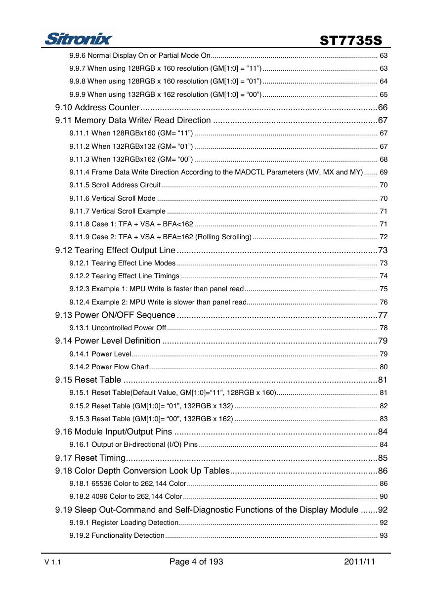
9.9.6 Normal Display On or Partial Mode On.................................................................................... 63
9.9.7 When using 128RGB x 160 resolution (GM[1:0] = “11”).......................................................... 63
9.9.8 When using 128RGB x 160 resolution (GM[1:0] = “01”).......................................................... 64
9.9.9 When using 132RGB x 162 resolution (GM[1:0] = “00”).......................................................... 65
9.10 Address Counter..................................................................................................66
9.11 Memory Data Write/ Read Direction ....................................................................67
9.11.1 When 128RGBx160 (GM= “11”) ............................................................................................ 67
9.11.2 When 132RGBx132 (GM= “01”) ............................................................................................ 67
9.11.3 When 132RGBx162 (GM= “00”) ............................................................................................ 68
9.11.4 Frame Data Write Direction According to the MADCTL Parameters (MV, MX and MY) ....... 69
9.11.5 Scroll Address Circuit............................................................................................................. 70
9.11.6 Vertical Scroll Mode ............................................................................................................... 70
9.11.7 Vertical Scroll Example .......................................................................................................... 71
9.11.8 Case 1: TFA + VSA + BFA<162 ............................................................................................ 71
9.11.9 Case 2: TFA + VSA + BFA=162 (Rolling Scrolling) ............................................................... 72
9.12 Tearing Effect Output Line ...................................................................................73
9.12.1 Tearing Effect Line Modes ..................................................................................................... 73
9.12.2 Tearing Effect Line Timings ................................................................................................... 74
9.12.3 Example 1: MPU Write is faster than panel read ................................................................... 75
9.12.4 Example 2: MPU Write is slower than panel read.................................................................. 76
9.13 Power ON/OFF Sequence ...................................................................................77
9.13.1 Uncontrolled Power Off .......................................................................................................... 78
9.14 Power Level Definition .........................................................................................79
9.14.1 Power Level............................................................................................................................ 79
9.14.2 Power Flow Chart................................................................................................................... 80
9.15 Reset Table .........................................................................................................81
9.15.1 Reset Table(Default Value, GM[1:0]=“11”, 128RGB x 160)................................................... 81
9.15.2 Reset Table (GM[1:0]= “01”, 132RGB x 132) ........................................................................ 82
9.15.3 Reset Table (GM[1:0]= “00”, 132RGB x 162) ........................................................................ 83
9.16 Module Input/Output Pins ....................................................................................84
9.16.1 Output or Bi-directional (I/O) Pins .......................................................................................... 84
9.17 Reset Timing........................................................................................................85
9.18 Color Depth Conversion Look Up Tables.............................................................86
9.18.1 65536 Color to 262,144 Color................................................................................................ 86
9.18.2 4096 Color to 262,144 Color .................................................................................................. 90
9.19 Sleep Out-Command and Self-Diagnostic Functions of the Display Module .......92
9.19.1 Register Loading Detection.................................................................................................... 92
9.19.2 Functionality Detection........................................................................................................... 93
V 1.1 Page 4 of 193 2011/11
�
ST7735S
9.19.3 Chip Attachment Detection (Optional) ................................................................................... 94
9.19.4 Display Glass Break Detection (Optional).............................................................................. 95
10 COMMAND........................................................................................... 96
10.1 System Function Command List and Description ................................................96
10.1.1 NOP (00h) .............................................................................................................................. 99
10.1.2 SWRESET (01h): Software Reset ....................................................................................... 100
10.1.3 RDDID (04h): Read Display ID ............................................................................................ 101
10.1.4 RDDST (09h): Read Display Status..................................................................................... 102
10.1.5 RDDPM (0Ah): Read Display Power Mode ......................................................................... 104
10.1.6 RDDMADCTL (0Bh): Read Display MADCTL ..................................................................... 105
10.1.7 RDDCOLMOD (0Ch): Read Display Pixel Format............................................................... 106
10.1.8 RDDIM (0Dh): Read Display Image Mode........................................................................... 107
10.1.9 RDDSM (0Eh): Read Display Signal Mode.......................................................................... 108
10.1.10 RDDSDR (0Fh): Read Display Self-Diagnostic Result ...................................................... 110
10.1.11 SLPIN (10h): Sleep In ........................................................................................................ 111
10.1.12 SLPOUT (11h): Sleep Out ................................................................................................. 112
10.1.13 PTLON (12h): Partial Display Mode On............................................................................. 113
10.1.14 NORON (13h): Normal Display Mode On .......................................................................... 114
10.1.15 INVOFF (20h): Display Inversion Off ................................................................................. 115
10.1.16 INVON (21h): Display Inversion On ................................................................................... 116
10.1.17 GAMSET (26h): Gamma Set ............................................................................................. 117
10.1.18 DISPOFF (28h): Display Off............................................................................................... 118
10.1.19 DISPON (29h): Display On ................................................................................................ 119
10.1.20 CASET (2Ah): Column Address Set .................................................................................. 120
10.1.21 RASET (2Bh): Row Address Set ....................................................................................... 122
10.1.22 RAMWR (2Ch): Memory Write........................................................................................... 124
10.1.23 RGBSET (2Dh): Color Setting for 4K, 65K and 262K........................................................ 125
10.1.24 RAMRD (2Eh): Memory Read ........................................................................................... 126
10.1.25 PTLAR (30h): Partial Area ................................................................................................. 127
10.1.26 SCRLAR (33h): Scroll Area Set ......................................................................................... 129
10.1.27 TEOFF (34h): Tearing Effect Line OFF ............................................................................. 131
10.1.28 TEON (35h): Tearing Effect Line ON ................................................................................. 132
10.1.29 MADCTL (36h): Memory Data Access Control .................................................................. 134
10.1.30 VSCSAD: Vertical Scroll Start Address of RAM (37h)....................................................... 137
10.1.31 IDMOFF (38h): Idle Mode Off ............................................................................................ 139
10.1.32 IDMON (39h): Idle Mode On .............................................................................................. 140
10.1.33 COLMOD (3Ah): Interface Pixel Format ............................................................................ 142
10.1.34 RDID1 (DAh): Read ID1 Value........................................................................................... 143
V 1.1 Page 5 of 193 2011/11
�
ST7735S
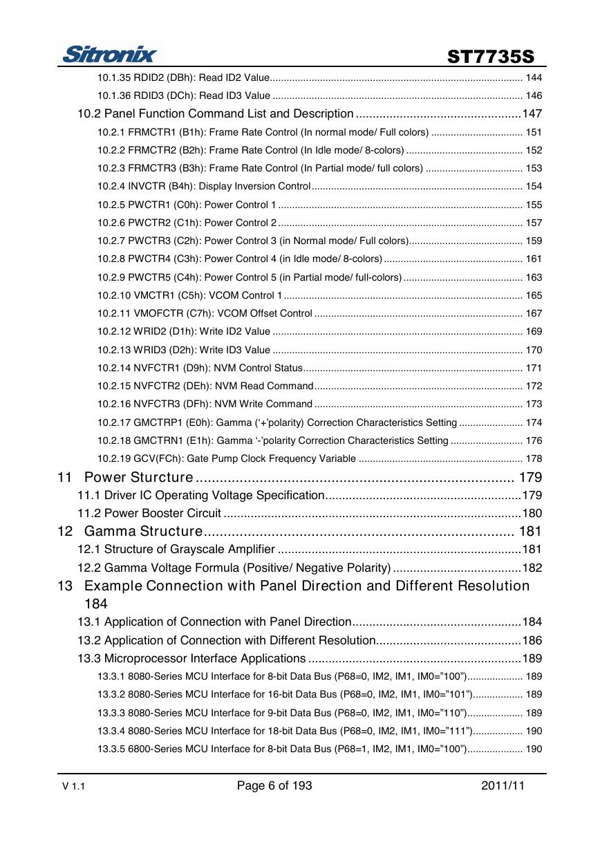
10.1.35 RDID2 (DBh): Read ID2 Value........................................................................................... 144
10.1.36 RDID3 (DCh): Read ID3 Value .......................................................................................... 146
10.2 Panel Function Command List and Description .................................................147
10.2.1 FRMCTR1 (B1h): Frame Rate Control (In normal mode/ Full colors) ................................. 151
10.2.2 FRMCTR2 (B2h): Frame Rate Control (In Idle mode/ 8-colors) .......................................... 152
10.2.3 FRMCTR3 (B3h): Frame Rate Control (In Partial mode/ full colors) ................................... 153
10.2.4 INVCTR (B4h): Display Inversion Control............................................................................ 154
10.2.5 PWCTR1 (C0h): Power Control 1 ........................................................................................ 155
10.2.6 PWCTR2 (C1h): Power Control 2 ........................................................................................ 157
10.2.7 PWCTR3 (C2h): Power Control 3 (in Normal mode/ Full colors)......................................... 159
10.2.8 PWCTR4 (C3h): Power Control 4 (in Idle mode/ 8-colors) .................................................. 161
10.2.9 PWCTR5 (C4h): Power Control 5 (in Partial mode/ full-colors) ........................................... 163
10.2.10 VMCTR1 (C5h): VCOM Control 1...................................................................................... 165
10.2.11 VMOFCTR (C7h): VCOM Offset Control ........................................................................... 167
10.2.12 WRID2 (D1h): Write ID2 Value .......................................................................................... 169
10.2.13 WRID3 (D2h): Write ID3 Value .......................................................................................... 170
10.2.14 NVFCTR1 (D9h): NVM Control Status............................................................................... 171
10.2.15 NVFCTR2 (DEh): NVM Read Command........................................................................... 172
10.2.16 NVFCTR3 (DFh): NVM Write Command ........................................................................... 173
10.2.17 GMCTRP1 (E0h): Gamma (‘+’polarity) Correction Characteristics Setting ....................... 174
10.2.18 GMCTRN1 (E1h): Gamma ‘-’polarity Correction Characteristics Setting .......................... 176
10.2.19 GCV(FCh): Gate Pump Clock Frequency Variable ........................................................... 178
11 Power Sturcture ................................................................................ 179
11.1 Driver IC Operating Voltage Specification..........................................................179
11.2 Power Booster Circuit ........................................................................................180
12 Gamma Structure.............................................................................. 181
12.1 Structure of Grayscale Amplifier ........................................................................181
12.2 Gamma Voltage Formula (Positive/ Negative Polarity) ......................................182
13 Example Connection with Panel Direction and Different Resolution
184
13.1 Application of Connection with Panel Direction..................................................184
13.2 Application of Connection with Different Resolution...........................................186
13.3 Microprocessor Interface Applications ...............................................................189
13.3.1 8080-Series MCU Interface for 8-bit Data Bus (P68=0, IM2, IM1, IM0=”100”).................... 189
13.3.2 8080-Series MCU Interface for 16-bit Data Bus (P68=0, IM2, IM1, IM0=”101”).................. 189
13.3.3 8080-Series MCU Interface for 9-bit Data Bus (P68=0, IM2, IM1, IM0=”110”).................... 189
13.3.4 8080-Series MCU Interface for 18-bit Data Bus (P68=0, IM2, IM1, IM0=”111”).................. 190
13.3.5 6800-Series MCU Interface for 8-bit Data Bus (P68=1, IM2, IM1, IM0=”100”).................... 190
V 1.1 Page 6 of 193 2011/11
�
ST7735S
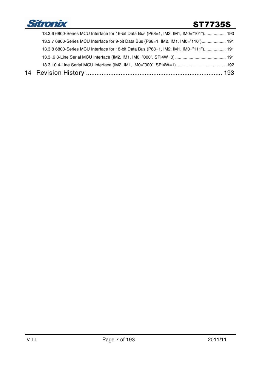
13.3.6 6800-Series MCU Interface for 16-bit Data Bus (P68=1, IM2, IM1, IM0=”101”).................. 190
13.3.7 6800-Series MCU Interface for 9-bit Data Bus (P68=1, IM2, IM1, IM0=”110”).................... 191
13.3.8 6800-Series MCU Interface for 18-bit Data Bus (P68=1, IM2, IM1, IM0=”111”).................. 191
13.3..9 3-Line Serial MCU Interface (IM2, IM1, IM0=”000”, SPI4W=0) .......................................... 191
13.3.10 4-Line Serial MCU Interface (IM2, IM1, IM0=”000”, SPI4W=1) ......................................... 192
14 Revision History ............................................................................... 193
V 1.1 Page 7 of 193 2011/11
�
ST7735S
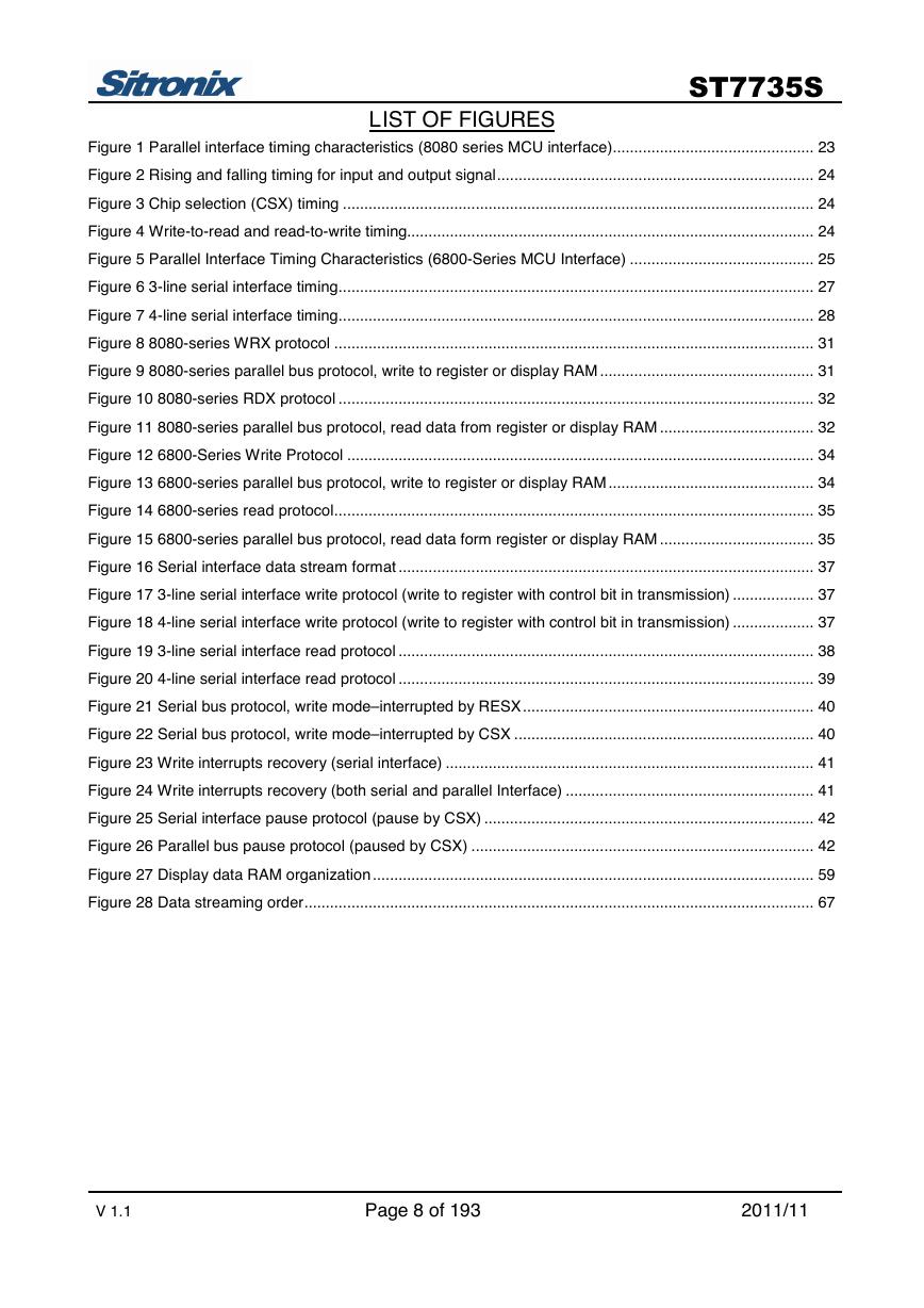
LIST OF FIGURES
Figure 1 Parallel interface timing characteristics (8080 series MCU interface)............................................... 23
Figure 2 Rising and falling timing for input and output signal.......................................................................... 24
Figure 3 Chip selection (CSX) timing .............................................................................................................. 24
Figure 4 Write-to-read and read-to-write timing............................................................................................... 24
Figure 5 Parallel Interface Timing Characteristics (6800-Series MCU Interface) ........................................... 25
Figure 6 3-line serial interface timing............................................................................................................... 27
Figure 7 4-line serial interface timing............................................................................................................... 28
Figure 8 8080-series WRX protocol ................................................................................................................ 31
Figure 9 8080-series parallel bus protocol, write to register or display RAM .................................................. 31
Figure 10 8080-series RDX protocol ............................................................................................................... 32
Figure 11 8080-series parallel bus protocol, read data from register or display RAM .................................... 32
Figure 12 6800-Series Write Protocol ............................................................................................................. 34
Figure 13 6800-series parallel bus protocol, write to register or display RAM ................................................ 34
Figure 14 6800-series read protocol................................................................................................................ 35
Figure 15 6800-series parallel bus protocol, read data form register or display RAM .................................... 35
Figure 16 Serial interface data stream format ................................................................................................. 37
Figure 17 3-line serial interface write protocol (write to register with control bit in transmission) ................... 37
Figure 18 4-line serial interface write protocol (write to register with control bit in transmission) ................... 37
Figure 19 3-line serial interface read protocol ................................................................................................. 38
Figure 20 4-line serial interface read protocol ................................................................................................. 39
Figure 21 Serial bus protocol, write mode–interrupted by RESX.................................................................... 40
Figure 22 Serial bus protocol, write mode–interrupted by CSX ...................................................................... 40
Figure 23 Write interrupts recovery (serial interface) ...................................................................................... 41
Figure 24 Write interrupts recovery (both serial and parallel Interface) .......................................................... 41
Figure 25 Serial interface pause protocol (pause by CSX) ............................................................................. 42
Figure 26 Parallel bus pause protocol (paused by CSX) ................................................................................ 42
Figure 27 Display data RAM organization ....................................................................................................... 59
Figure 28 Data streaming order....................................................................................................................... 67
V 1.1 Page 8 of 193 2011/11
�


 V2版本原理图(Capacitive-Fingerprint-Reader-Schematic_V2).pdf
 摄像头工作原理.doc
 VL53L0X简要说明(En.FLVL53L00216).pdf
 原理图(DVK720-Schematic).pdf
 原理图(Pico-Clock-Green-Schdoc).pdf
 原理图(RS485-CAN-HAT-B-schematic).pdf
 File:SIM7500_SIM7600_SIM7800 Series_SSL_Application Note_V2.00.pdf
 ADS1263(Ads1262).pdf
 原理图(Open429Z-D-Schematic).pdf
 用户手册(Capacitive_Fingerprint_Reader_User_Manual_CN).pdf
 CY7C68013A(英文版)(CY7C68013A).pdf
 TechnicalReference_Dem.pdf