1745 Technology Drive, San Jose, CA 95110 U.S.A.
Tel: +1 (408) 988-7339 Fax: +1 (408) 988-8104
InvenSense Inc.
Website: www.invensense.com
Document Number: DS-000007
Revision: 1.0
Release Date: 09/14/2014
MPU-9255
Product Specification
MPU-9255-01
�
MPU-9255 Product Specification
Document Number: DS-000007
Revision: 1.0
Release Date: 09/14/2014
1.1
1.2
1.3
1.4
2.1
2.2
2.3
2.4
2.5
CONTENTS
1 DOCUMENT INFORMATION ...................................................................................................................... 4
REVISION HISTORY .............................................................................................................................. 4
PURPOSE AND SCOPE .......................................................................................................................... 5
PRODUCT OVERVIEW ........................................................................................................................... 5
APPLICATIONS ..................................................................................................................................... 5
2 FEATURES .................................................................................................................................................. 6
GYROSCOPE FEATURES ....................................................................................................................... 6
ACCELEROMETER FEATURES ............................................................................................................... 6
MAGNETOMETER FEATURES ................................................................................................................. 6
ADDITIONAL FEATURES ........................................................................................................................ 6
MOTIONPROCESSING ........................................................................................................................... 7
3 ELECTRICAL CHARACTERISTICS ........................................................................................................... 8
GYROSCOPE SPECIFICATIONS .............................................................................................................. 8
ACCELEROMETER SPECIFICATIONS ....................................................................................................... 9
MAGNETOMETER SPECIFICATIONS ...................................................................................................... 10
ELECTRICAL SPECIFICATIONS ............................................................................................................. 11
I2C TIMING CHARACTERIZATION ......................................................................................................... 15
SPI TIMING CHARACTERIZATION ......................................................................................................... 16
ABSOLUTE MAXIMUM RATINGS ........................................................................................................... 18
4 APPLICATIONS INFORMATION .............................................................................................................. 19
PIN OUT AND SIGNAL DESCRIPTION .................................................................................................... 19
4.1
TYPICAL OPERATING CIRCUIT ............................................................................................................. 20
4.2
BILL OF MATERIALS FOR EXTERNAL COMPONENTS .............................................................................. 20
4.3
BLOCK DIAGRAM ............................................................................................................................... 21
4.4
OVERVIEW ........................................................................................................................................ 22
4.5
THREE-AXIS MEMS GYROSCOPE WITH 16-BIT ADCS AND SIGNAL CONDITIONING ................................ 22
4.6
THREE-AXIS MEMS ACCELEROMETER WITH 16-BIT ADCS AND SIGNAL CONDITIONING ........................ 22
4.7
THREE-AXIS MEMS MAGNETOMETER WITH 16-BIT ADCS AND SIGNAL CONDITIONING ......................... 22
4.8
DIGITAL MOTION PROCESSOR ............................................................................................................ 22
4.9
PRIMARY I2C AND SPI SERIAL COMMUNICATIONS INTERFACES ............................................................ 23
4.10
AUXILIARY I2C SERIAL INTERFACE ...................................................................................................... 23
4.11
SELF-TEST ........................................................................................................................................ 24
4.12
4.13 MPU-9255 SOLUTION USING I2C INTERFACE ..................................................................................... 25
3.1
3.2
3.3
3.4
3.5
3.6
3.7
MPU-9255-01
Page 2 of 42
�
MPU-9255 Product Specification
Document Number: DS-000007
Revision: 1.0
Release Date: 09/14/2014
6.1
4.14 MPU-9255 SOLUTION USING SPI INTERFACE ..................................................................................... 26
4.15 CLOCKING ......................................................................................................................................... 26
SENSOR DATA REGISTERS ................................................................................................................. 27
4.16
FIFO ................................................................................................................................................ 27
4.17
4.18
INTERRUPTS ...................................................................................................................................... 27
4.19 DIGITAL-OUTPUT TEMPERATURE SENSOR .......................................................................................... 27
4.20
BIAS AND LDO .................................................................................................................................. 28
4.21 CHARGE PUMP .................................................................................................................................. 28
STANDARD POWER MODE .................................................................................................................. 28
4.22
4.23
POWER SEQUENCING REQUIREMENTS AND POWER ON RESET ............................................................ 28
5 ADVANCED HARDWARE FEATURES .................................................................................................... 29
6 PROGRAMMABLE INTERRUPTS ............................................................................................................ 30
WAKE-ON-MOTION INTERRUPT ........................................................................................................... 30
7 DIGITAL INTERFACE ............................................................................................................................... 32
I2C AND SPI SERIAL INTERFACES ...................................................................................................... 32
I2C INTERFACE .................................................................................................................................. 32
I2C COMMUNICATIONS PROTOCOL ..................................................................................................... 32
I2C TERMS ........................................................................................................................................ 35
SPI INTERFACE ................................................................................................................................. 36
8 SERIAL INTERFACE CONSIDERATIONS ............................................................................................... 37
MPU-9255 SUPPORTED INTERFACES ................................................................................................. 37
9 ASSEMBLY ............................................................................................................................................... 38
ORIENTATION OF AXES ...................................................................................................................... 38
PACKAGE DIMENSIONS ...................................................................................................................... 38
10 PART NUMBER PACKAGE MARKING ................................................................................................... 40
11 RELIABILITY ............................................................................................................................................. 41
11.1 QUALIFICATION TEST POLICY ............................................................................................................. 41
11.2 QUALIFICATION TEST PLAN ................................................................................................................ 41
12 REFERENCE ............................................................................................................................................. 42
7.1
7.2
7.3
7.4
7.5
8.1
9.1
9.2
MPU-9255-01
Page 3 of 42
�
MPU-9255 Product Specification
Document Number: DS-000007
Revision: 1.0
Release Date: 09/14/2014
1 Document Information
1.1 Revision History
Revision
Date
09/14/2014
Revision Description
1.0
Initial Release
MPU-9255-01
Page 4 of 42
�
MPU-9255 Product Specification
Document Number: DS-000007
Revision: 1.0
Release Date: 09/14/2014
the MPU-9255
from Asahi Kasei Microdevices Corporation. Hence,
1.2 Purpose and Scope
This document is a preliminary product specification, providing a description, specifications, and design
related information on the MPU-9255™ MotionTracking device. The device is housed in a small 3x3x1mm
QFN package.
Specifications are subject to change without notice. Final specifications will be updated based upon
characterization of production silicon. For references to register map and descriptions of individual registers,
please refer to the MPU-9255 Register Map and Register Descriptions document.
1.3 Product Overview
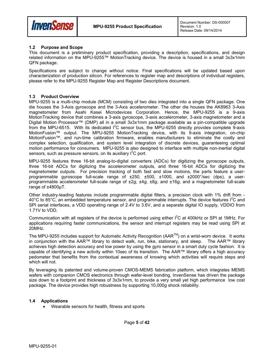
MPU-9255 is a multi-chip module (MCM) consisting of two dies integrated into a single QFN package. One
die houses the 3-Axis gyroscope and the 3-Axis accelerometer. The other die houses the AK8963 3-Axis
magnetometer
is a 9-axis
MotionTracking device that combines a 3-axis gyroscope, 3-axis accelerometer, 3-axis magnetometer and a
Digital Motion Processor™ (DMP) all in a small 3x3x1mm package available as a pin-compatible upgrade
from the MPU-6515. With its dedicated I2C sensor bus, the MPU-9255 directly provides complete 9-axis
MotionFusion™ output. The MPU-9255 MotionTracking device, with its 9-axis integration, on-chip
MotionFusion™, and run-time calibration firmware, enables manufacturers to eliminate the costly and
complex selection, qualification, and system level integration of discrete devices, guaranteeing optimal
motion performance for consumers. MPU-9255 is also designed to interface with multiple non-inertial digital
sensors, such as pressure sensors, on its auxiliary I2C port.
MPU-9255 features three 16-bit analog-to-digital converters (ADCs) for digitizing the gyroscope outputs,
three 16-bit ADCs for digitizing the accelerometer outputs, and three 16-bit ADCs for digitizing the
magnetometer outputs. For precision tracking of both fast and slow motions, the parts feature a user-
programmable gyroscope full-scale range of ±250, ±500, ±1000, and ±2000°/sec (dps), a user-
programmable accelerometer full-scale range of ±2g, ±4g, ±8g, and ±16g, and a magnetometer full-scale
range of ±4800µT.
Other industry-leading features include programmable digital filters, a precision clock with 1% drift from -
40°C to 85°C, an embedded temperature sensor, and programmable interrupts. The device features I2C and
SPI serial interfaces, a VDD operating range of 2.4V to 3.6V, and a separate digital IO supply, VDDIO from
1.71V to VDD.
Communication with all registers of the device is performed using either I2C at 400kHz or SPI at 1MHz. For
applications requiring faster communications, the sensor and interrupt registers may be read using SPI at
20MHz.
The MPU-9255 includes support for Automatic Activity Recognition (AARTM) on a wrist-worn device. It works
in conjunction with the AAR™ library to detect walk, run, bike, stationary, and sleep. The AAR™ library
achieves high detection accuracy and low power by using the gyro sensor in a smart duty cycle fashion. It is
capable of identifying a new activity within 10sec of its transition. The AAR™ library offers a high accuracy
pedometer that benefits from the contextual awareness of knowing which activities will require steps and
which will not.
By leveraging its patented and volume-proven CMOS-MEMS fabrication platform, which integrates MEMS
wafers with companion CMOS electronics through wafer-level bonding, InvenSense has driven the package
size down to a footprint and thickness of 3x3x1mm, to provide a very small yet high performance low cost
package. The device provides high robustness by supporting 10,000g shock reliability.
1.4 Applications
Wearable sensors for health, fitness and sports
MPU-9255-01
Page 5 of 42
�
MPU-9255 Product Specification
Document Number: DS-000007
Revision: 1.0
Release Date: 09/14/2014
2 Features
2.1 Gyroscope Features
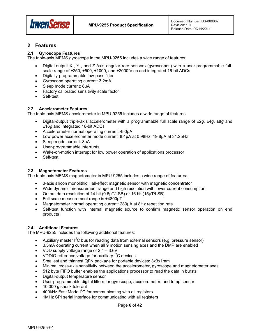
The triple-axis MEMS gyroscope in the MPU-9255 includes a wide range of features:
Digital-output X-, Y-, and Z-Axis angular rate sensors (gyroscopes) with a user-programmable full-
scale range of ±250, ±500, ±1000, and ±2000°/sec and integrated 16-bit ADCs
Digitally-programmable low-pass filter
Gyroscope operating current: 3.2mA
Sleep mode current: 8µA
Factory calibrated sensitivity scale factor
Self-test
2.2 Accelerometer Features
The triple-axis MEMS accelerometer in MPU-9255 includes a wide range of features:
Digital-output triple-axis accelerometer with a programmable full scale range of ±2g, ±4g, ±8g and
±16g and integrated 16-bit ADCs
Accelerometer normal operating current: 450µA
Low power accelerometer mode current: 8.4µA at 0.98Hz, 19.8µA at 31.25Hz
Sleep mode current: 8µA
User-programmable interrupts
Wake-on-motion interrupt for low power operation of applications processor
Self-test
2.3 Magnetometer Features
The triple-axis MEMS magnetometer in MPU-9255 includes a wide range of features:
3-axis silicon monolithic Hall-effect magnetic sensor with magnetic concentrator
Wide dynamic measurement range and high resolution with lower current consumption.
Output data resolution of 14 bit (0.6µT/LSB) or 16 bit (15µT/LSB)
Full scale measurement range is ±4800µT
Magnetometer normal operating current: 280µA at 8Hz repetition rate
Self-test function with internal magnetic source to confirm magnetic sensor operation on end
products
2.4 Additional Features
The MPU-9255 includes the following additional features:
Auxiliary master I2C bus for reading data from external sensors (e.g. pressure sensor)
3.5mA operating current when all 9 motion sensing axes and the DMP are enabled
VDD supply voltage range of 2.4 – 3.6V
VDDIO reference voltage for auxiliary I2C devices
Smallest and thinnest QFN package for portable devices: 3x3x1mm
Minimal cross-axis sensitivity between the accelerometer, gyroscope and magnetometer axes
512 byte FIFO buffer enables the applications processor to read the data in bursts
Digital-output temperature sensor
User-programmable digital filters for gyroscope, accelerometer, and temp sensor
10,000 g shock tolerant
400kHz Fast Mode I2C for communicating with all registers
1MHz SPI serial interface for communicating with all registers
MPU-9255-01
Page 6 of 42
�
MPU-9255 Product Specification
Document Number: DS-000007
Revision: 1.0
Release Date: 09/14/2014
20MHz SPI serial interface for reading sensor and interrupt registers
MEMS structure hermetically sealed and bonded at wafer level
RoHS and Green compliant
2.5 MotionProcessing
Internal Digital Motion Processing™ (DMP™) engine supports advanced MotionProcessing and low
power functions such as gesture recognition using programmable interrupts
Low-power pedometer functionality allows the host processor to sleep while the DMP maintains the
step count.
MPU-9255-01
Page 7 of 42
�
MPU-9255 Product Specification
Document Number: DS-000007
Revision: 1.0
Release Date: 09/14/2014
MIN
MAX
TYP
±250
±500
±1000
±2000
3 Electrical Characteristics
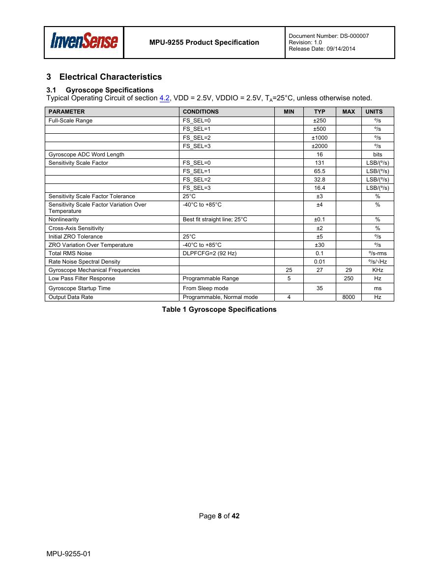
3.1 Gyroscope Specifications
Typical Operating Circuit of section 4.2, VDD = 2.5V, VDDIO = 2.5V, TA=25°C, unless otherwise noted.
PARAMETER
Full-Scale Range
Gyroscope ADC Word Length
Sensitivity Scale Factor
Sensitivity Scale Factor Tolerance
Sensitivity Scale Factor Variation Over
Temperature
Nonlinearity
Cross-Axis Sensitivity
Initial ZRO Tolerance
ZRO Variation Over Temperature
Total RMS Noise
Rate Noise Spectral Density
Gyroscope Mechanical Frequencies
Low Pass Filter Response
Gyroscope Startup Time
Output Data Rate
Best fit straight line; 25°C
25°C
-40°C to +85°C
DLPFCFG=2 (92 Hz)
Programmable Range
From Sleep mode
Programmable, Normal mode
CONDITIONS
FS_SEL=0
FS_SEL=1
FS_SEL=2
FS_SEL=3
FS_SEL=0
FS_SEL=1
FS_SEL=2
FS_SEL=3
25°C
-40°C to +85°C
±0.1
±2
±5
±30
0.1
0.01
27
35
16
131
65.5
32.8
16.4
±3
±4
29
250
8000
25
5
4
UNITS
º/s
º/s
º/s
º/s
bits
LSB/(º/s)
LSB/(º/s)
LSB/(º/s)
LSB/(º/s)
%
%
%
%
º/s
º/s
º/s-rms
º/s/√Hz
KHz
Hz
ms
Hz
Table 1 Gyroscope Specifications
MPU-9255-01
Page 8 of 42
�



 V2版本原理图(Capacitive-Fingerprint-Reader-Schematic_V2).pdf
 摄像头工作原理.doc
 VL53L0X简要说明(En.FLVL53L00216).pdf
 原理图(DVK720-Schematic).pdf
 原理图(Pico-Clock-Green-Schdoc).pdf
 原理图(RS485-CAN-HAT-B-schematic).pdf
 File:SIM7500_SIM7600_SIM7800 Series_SSL_Application Note_V2.00.pdf
 ADS1263(Ads1262).pdf
 原理图(Open429Z-D-Schematic).pdf
 用户手册(Capacitive_Fingerprint_Reader_User_Manual_CN).pdf
 CY7C68013A(英文版)(CY7C68013A).pdf
 TechnicalReference_Dem.pdf