ILI9488
a-Si TFT LCD Single Chip Driver
320(RGB) x 480 Resolution, 16.7M-color
With Internal GRAM
Specification
Version: V100
Document No: ILI9488_IDT_V100_20121128
ILI TECHNOLOGY CORP.
8F, No. 38, Taiyuan St, Jhubei City,
Taiwan 302, R.O.C.
Tel.886-3-5600099; Fax.886-3-5600585
http://www.ilitek.com
�
a-Si TFT LCD Single Chip Driver
320RGB x 480 Resolution and 16.7M-color
ILI9488
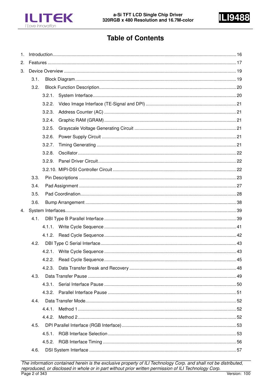
Table of Contents
1.
Introduction .................................................................................................................................................. 16
2. Features ...................................................................................................................................................... 17
3. Device Overview ......................................................................................................................................... 19
3.1. Block Diagram ................................................................................................................................ 19
3.2. Block Function Description ............................................................................................................. 20
3.2.1. System Interface .................................................................................................................. 20
3.2.2. Video Image Interface (TE-Signal and DPI) ........................................................................ 21
3.2.3. Address Counter (AC) ......................................................................................................... 21
3.2.4. Graphic RAM (GRAM) ......................................................................................................... 21
3.2.5. Grayscale Voltage Generating Circuit ................................................................................. 21
3.2.6. Power Supply Circuit ........................................................................................................... 21
3.2.7. Timing Generating ............................................................................................................... 21
3.2.8. Oscillator .............................................................................................................................. 22
3.2.9. Panel Driver Circuit .............................................................................................................. 22
3.2.10. MIPI-DSI Controller Circuit .................................................................................................. 22
3.3. Pin Descriptions ............................................................................................................................. 23
3.4. Pad Assignment ............................................................................................................................. 27
3.5. Pad Coordination............................................................................................................................ 28
3.6. Bump Arrangement ........................................................................................................................ 38
4. System Interfaces ........................................................................................................................................ 39
4.1. DBI Type B Parallel Interface ......................................................................................................... 39
4.1.1. Write Cycle Sequence ......................................................................................................... 41
4.1.2. Read Cycle Sequence ......................................................................................................... 42
4.2. DBI Type C Serial Interface ............................................................................................................ 43
4.2.1. Write Cycle Sequence ......................................................................................................... 43
4.2.2. Read Cycle Sequence ......................................................................................................... 45
4.2.3. Data Transfer Break and Recovery ..................................................................................... 48
4.3. Data Transfer Pause ...................................................................................................................... 49
4.3.1. Serial Interface Pause ......................................................................................................... 50
4.3.2. Parallel Interface Pause ...................................................................................................... 51
4.4. Data Transfer Mode ........................................................................................................................ 52
4.4.1. Method 1 .............................................................................................................................. 52
4.4.2. Method 2 .............................................................................................................................. 52
4.5. DPI Parallel Interface (RGB Interface) ........................................................................................... 53
4.5.1. RGB Interface Selection ...................................................................................................... 53
4.5.2. RGB Interface Timing .......................................................................................................... 56
4.6. DSI System Interface ..................................................................................................................... 57
The information contained herein is the exclusive property of ILI Technology Corp. and shall not be distributed,
reproduced, or disclosed in whole or in part without prior written permission of ILI Technology Corp.
Page 2 of 343
Version: 100
�
a-Si TFT LCD Single Chip Driver
320RGB x 480 Resolution and 16.7M-color
ILI9488
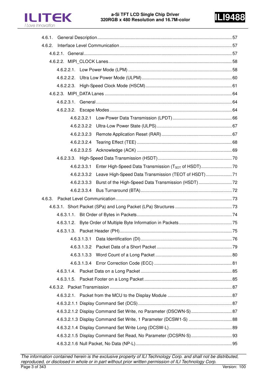
4.6.1. General Description ............................................................................................................. 57
4.6.2.
Interface Level Communication ........................................................................................... 57
4.6.2.1. General ........................................................................................................................ 57
4.6.2.2. MIPI_CLOCK Lanes .................................................................................................... 58
4.6.2.2.1. Low Power Mode (LPM) .................................................................................... 58
4.6.2.2.2. Ultra Low Power Mode (ULPM) ......................................................................... 60
4.6.2.2.3. High-Speed Clock Mode (HSCM) ...................................................................... 61
4.6.2.3. MIPI_DATA Lanes ....................................................................................................... 64
4.6.2.3.1. General .............................................................................................................. 64
4.6.2.3.2. Escape Modes ................................................................................................... 64
4.6.2.3.2.1 Low-Power Data Transmission (LPDT) ................................................ 66
4.6.2.3.2.2 Ultra-Low Power State (ULPS) ............................................................. 67
4.6.2.3.2.3 Remote Application Reset (RAR) ......................................................... 67
4.6.2.3.2.4 Tearing Effect (TEE) ............................................................................. 68
4.6.2.3.2.5 Acknowledge (ACK) ............................................................................. 69
4.6.2.3.3. High-Speed Data Transmission (HSDT) ............................................................ 70
4.6.2.3.3.1 Enter High-Speed Data Transmission (TSOT of HSDT) ......................... 70
4.6.2.3.3.2 Leave High-Speed Data Transmission (TEOT of HSDT) ..................... 71
4.6.2.3.3.3 Burst of the High-Speed Data Transmission (HSDT) ........................... 72
4.6.2.3.3.4 Bus Turnaround (BTA) .......................................................................... 72
4.6.3. Packet Level Communication .............................................................................................. 73
4.6.3.1. Short Packet (SPa) and Long Packet (LPa) Structures .............................................. 73
4.6.3.1.1. Bit Order of Bytes in Packets ............................................................................. 74
4.6.3.1.2. Byte Order of Multiple Byte Information in Packets ........................................... 75
4.6.3.1.3. Packet Header (PH)........................................................................................... 75
4.6.3.1.3.1 Data Identification (DI) .......................................................................... 76
4.6.3.1.3.2 Packet Data of a Short Packet ............................................................. 79
4.6.3.1.3.3 Word Count of a Long Packet .............................................................. 80
4.6.3.1.3.4 Error Correction Code (ECC) ............................................................... 81
4.6.3.1.4. Packet Data on a Long Packet .......................................................................... 85
4.6.3.1.5. Packet Footer on a Long Packet ....................................................................... 85
4.6.3.2. Packet Transmission ................................................................................................... 87
4.6.3.2.1. Packet from the MCU to the Display Module .................................................... 87
4.6.3.2.1.1 Display Command Set (DCS) ............................................................................ 87
4.6.3.2.1.2 Display Command Set Write, no Parameter (DSCWN-S) ................................. 87
4.6.3.2.1.3 Display Command Set Write, 1 Parameter (DCSW1-S) ................................... 88
4.6.3.2.1.4 Display Command Set Write Long (DCSW-L) ................................................... 89
4.6.3.2.1.5 Display Command Set Read, No Parameter (DCSRN-S) ................................. 93
4.6.3.2.1.6 Null Packet, No Data (NP-L) .............................................................................. 95
The information contained herein is the exclusive property of ILI Technology Corp. and shall not be distributed,
reproduced, or disclosed in whole or in part without prior written permission of ILI Technology Corp.
Page 3 of 343
Version: 100
�
a-Si TFT LCD Single Chip Driver
320RGB x 480 Resolution and 16.7M-color
ILI9488
4.6.3.2.1.7 End of Transmission Packet (EoTP) .................................................................. 97
4.6.3.2.2. Packet from the Display Module to the MCU .................................................... 98
4.6.3.2.2.1. Used Packet Type .............................................................................................. 98
4.6.3.2.2.2 Acknowledge with Error Report ....................................................................... 100
4.6.3.2.2.3 DCS Read Long Response (DCSRR-L) .......................................................... 102
4.6.3.2.2.4 DCS Read Short Response, 1 Byte Returned (DCSRR1-S)........................... 104
4.6.3.2.2.5 DCS Read Short Response, 2 Bytes Returned (DCSRR2-S) ......................... 104
4.6.3.3. Communication Sequences ...................................................................................... 105
4.6.3.3.1. General ............................................................................................................ 105
4.6.3.3.2. Sequence ......................................................................................................... 106
4.6.3.3.2.1. DCS Write, 1 Parameter Sequence ................................................................. 106
4.6.3.3.2.2. DCS Write, No Parameter Sequence .............................................................. 107
4.6.3.3.2.3. DCS Write Long Sequence.............................................................................. 108
4.6.3.3.2.4. DCS Read, No Parameter Sequence .............................................................. 109
4.6.3.3.2.5. Null Packet, No Data Sequence .......................................................................111
4.6.3.3.2.6. End of Transmission Packet .............................................................................111
4.6.3.4. 16 Bit/Pixel Writing .................................................................................................... 112
4.6.3.5. 24 Bit/Pixel Writing .................................................................................................... 113
4.6.3.5.1. 24 Bit/Pixel Reading ........................................................................................ 115
4.7. Display Data Format ..................................................................................................................... 119
4.7.1. DBI Type C Option 1 (3-Line Serial Interface) ................................................................... 119
4.7.1.1. SPI Data for 3-bit/pixel (RGB 1-1-1 Bits Input), 8-color ............................................ 119
4.7.1.2. SPI Data for 18-bit/pixel (RGB 6-6-6 Bits Input), 262K-color .................................... 120
4.7.2. DBI Type-C Option 3 (4-Line Serial Interface) ................................................................... 121
4.7.2.1. SPI Data for 3-bit/pixel (RGB 1-1-1 Bits Input), 8-color ............................................ 121
4.7.2.2. SPI Data for 18-bit/pixel (RGB 6-6-6 Bits Input), 262K-color .................................... 122
4.7.3. 8-bit Parallel MCU Interface .............................................................................................. 123
4.7.3.1. 8-bit Data Bus for 16-bit/pixel (RGB 5-6-5 Bits Input), 65K-color .............................. 123
4.7.3.2. 8-bit Data Bus for 18-bit/pixel (RGB 6-6-6 Bits Input), 262K-color............................ 124
4.7.4. 9-bit Parallel MCU Interface .............................................................................................. 125
4.7.4.1. 9-bit Data Bus for 18-bit/pixel (RGB 6-6-6 Bits Input), 262K-color............................ 125
4.7.5. 16-bit Parallel MCU Interface ............................................................................................ 126
4.7.5.1. 16-bit Data Bus for 16-bit/pixel (RGB 5-6-5 Bits Input), 65K-color ............................ 127
4.7.5.2. 16-bit Data Bus for 18-bit/pixel (RGB 6-6-6 Bits Input), 262K-color .......................... 128
4.7.6. 18-bit Parallel MCU Interface ............................................................................................ 129
4.7.6.1. 18-bit Data Bus for 18-bit/pixel (RGB 6-6-6 Bits Input), 262K-color .......................... 130
4.7.7. 24-bit Parallel MCU Interface ............................................................................................ 131
4.7.7.1. 24-bit Data Bus for 24-bit/pixel (RGB 8-8-8 Bits Input), 262K-color .......................... 132
4.8. DPI Parallel Interface
RGB Interface
..................................................................................... 133
The information contained herein is the exclusive property of ILI Technology Corp. and shall not be distributed,
reproduced, or disclosed in whole or in part without prior written permission of ILI Technology Corp.
Page 4 of 343
Version: 100
(
)
�
a-Si TFT LCD Single Chip Driver
320RGB x 480 Resolution and 16.7M-color
ILI9488
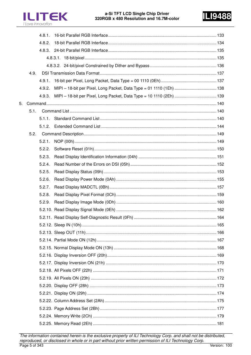
4.8.1. 16-bit Parallel RGB Interface ............................................................................................. 133
4.8.2. 18-bit Parallel RGB Interface ............................................................................................. 134
4.8.3. 24-bit Parallel RGB Interface ............................................................................................. 135
4.8.3.1. 18-bit/pixel ................................................................................................................. 135
4.8.3.2. 24-bit/pixel Constrained by Dither and Bypass ......................................................... 136
4.9. DSI Transmission Data Format .................................................................................................... 137
4.9.1. 16-bit per Pixel, Long Packet, Data Type = 00 1110 (0Eh) ................................................ 137
4.9.2. MIPI – 18-bit per Pixel, Long Packet, Data Type = 01 1110 (1Eh) .................................... 138
4.9.3. MIPI – 18-bit per Pixel, Long Packet, Data Type = 10 1110 (2Eh) .................................... 139
5. Command .................................................................................................................................................. 140
5.1. Command List .............................................................................................................................. 140
5.1.1. Standard Command List .................................................................................................... 140
5.1.2. Extended Command List ................................................................................................... 144
5.2. Command Description .................................................................................................................. 149
5.2.1. NOP (00h) .......................................................................................................................... 149
5.2.2. Software Reset (01h) ......................................................................................................... 150
5.2.3. Read Display Identification Information (04h) ................................................................... 151
5.2.4. Read Number of the Errors on DSI (05h) .......................................................................... 152
5.2.5. Read Display Status (09h) ................................................................................................. 153
5.2.6. Read Display Power Mode (0Ah) ...................................................................................... 155
5.2.7. Read Display MADCTL (0Bh) ............................................................................................ 157
5.2.8. Read Display Pixel Format (0Ch) ...................................................................................... 159
5.2.9. Read Display Image Mode (0Dh) ...................................................................................... 160
5.2.10. Read Display Signal Mode (0Eh) ...................................................................................... 162
5.2.11. Read Display Self-Diagnostic Result (0Fh) ....................................................................... 164
5.2.12. Sleep IN (10h) .................................................................................................................... 165
5.2.13. Sleep OUT (11h) ................................................................................................................ 166
5.2.14. Partial Mode ON (12h) ....................................................................................................... 167
5.2.15. Normal Display Mode ON (13h) ........................................................................................ 168
5.2.16. Display Inversion OFF (20h) .............................................................................................. 169
5.2.17. Display Inversion ON (21h) ............................................................................................... 170
5.2.18. All Pixels OFF (22h) .......................................................................................................... 171
5.2.19. All Pixels ON (23h) ............................................................................................................ 172
5.2.20. Display OFF (28h) ............................................................................................................. 173
5.2.21. Display ON (29h) ............................................................................................................... 174
5.2.22. Column Address Set (2Ah) ................................................................................................ 175
5.2.23. Page Address Set (2Bh) .................................................................................................... 177
5.2.24. Memory Write (2Ch) .......................................................................................................... 179
5.2.25. Memory Read (2Eh) .......................................................................................................... 181
The information contained herein is the exclusive property of ILI Technology Corp. and shall not be distributed,
reproduced, or disclosed in whole or in part without prior written permission of ILI Technology Corp.
Page 5 of 343
Version: 100
�
a-Si TFT LCD Single Chip Driver
320RGB x 480 Resolution and 16.7M-color
ILI9488
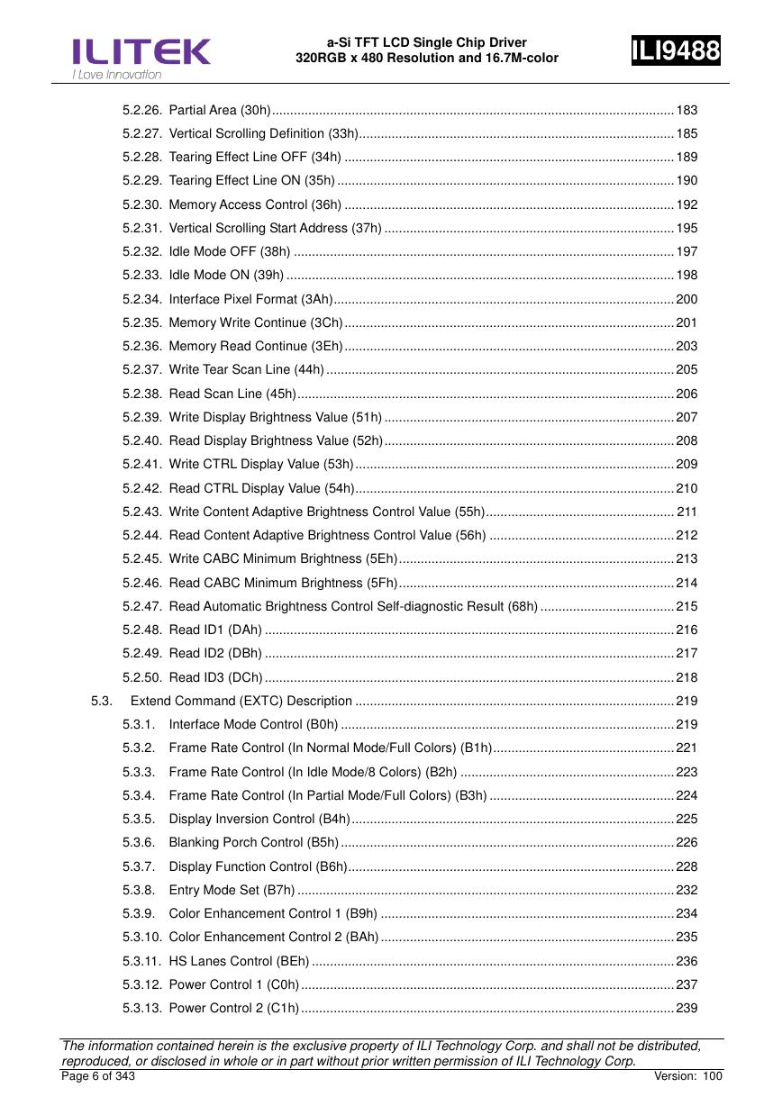
5.2.26. Partial Area (30h) ............................................................................................................... 183
5.2.27. Vertical Scrolling Definition (33h)....................................................................................... 185
5.2.28. Tearing Effect Line OFF (34h) ........................................................................................... 189
5.2.29. Tearing Effect Line ON (35h) ............................................................................................. 190
5.2.30. Memory Access Control (36h) ........................................................................................... 192
5.2.31. Vertical Scrolling Start Address (37h) ................................................................................ 195
5.2.32. Idle Mode OFF (38h) ......................................................................................................... 197
5.2.33. Idle Mode ON (39h) ........................................................................................................... 198
5.2.34. Interface Pixel Format (3Ah) .............................................................................................. 200
5.2.35. Memory Write Continue (3Ch) ........................................................................................... 201
5.2.36. Memory Read Continue (3Eh) ........................................................................................... 203
5.2.37. Write Tear Scan Line (44h) ................................................................................................ 205
5.2.38. Read Scan Line (45h) ........................................................................................................ 206
5.2.39. Write Display Brightness Value (51h) ................................................................................ 207
5.2.40. Read Display Brightness Value (52h) ................................................................................ 208
5.2.41. Write CTRL Display Value (53h) ........................................................................................ 209
5.2.42. Read CTRL Display Value (54h) ........................................................................................ 210
5.2.43. Write Content Adaptive Brightness Control Value (55h) .................................................... 211
5.2.44. Read Content Adaptive Brightness Control Value (56h) ................................................... 212
5.2.45. Write CABC Minimum Brightness (5Eh) ............................................................................ 213
5.2.46. Read CABC Minimum Brightness (5Fh) ............................................................................ 214
5.2.47. Read Automatic Brightness Control Self-diagnostic Result (68h) ..................................... 215
5.2.48. Read ID1 (DAh) ................................................................................................................. 216
5.2.49. Read ID2 (DBh) ................................................................................................................. 217
5.2.50. Read ID3 (DCh) ................................................................................................................. 218
5.3. Extend Command (EXTC) Description ........................................................................................ 219
5.3.1.
Interface Mode Control (B0h) ............................................................................................ 219
5.3.2. Frame Rate Control (In Normal Mode/Full Colors) (B1h) .................................................. 221
5.3.3. Frame Rate Control (In Idle Mode/8 Colors) (B2h) ........................................................... 223
5.3.4. Frame Rate Control (In Partial Mode/Full Colors) (B3h) ................................................... 224
5.3.5. Display Inversion Control (B4h) ......................................................................................... 225
5.3.6. Blanking Porch Control (B5h) ............................................................................................ 226
5.3.7. Display Function Control (B6h) .......................................................................................... 228
5.3.8. Entry Mode Set (B7h) ........................................................................................................ 232
5.3.9. Color Enhancement Control 1 (B9h) ................................................................................. 234
5.3.10. Color Enhancement Control 2 (BAh) ................................................................................. 235
5.3.11. HS Lanes Control (BEh) .................................................................................................... 236
5.3.12. Power Control 1 (C0h) ....................................................................................................... 237
5.3.13. Power Control 2 (C1h) ....................................................................................................... 239
The information contained herein is the exclusive property of ILI Technology Corp. and shall not be distributed,
reproduced, or disclosed in whole or in part without prior written permission of ILI Technology Corp.
Page 6 of 343
Version: 100
�
a-Si TFT LCD Single Chip Driver
320RGB x 480 Resolution and 16.7M-color
ILI9488
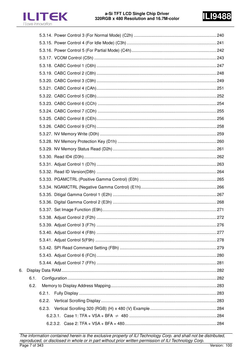
5.3.14. Power Control 3 (For Normal Mode) (C2h) ....................................................................... 240
5.3.15. Power Control 4 (For Idle Mode) (C3h) ............................................................................. 241
5.3.16. Power Control 5 (For Partial Mode) (C4h) ......................................................................... 242
5.3.17. VCOM Control (C5h) ......................................................................................................... 243
5.3.18. CABC Control 1 (C6h) ....................................................................................................... 247
5.3.19. CABC Control 2 (C8h) ....................................................................................................... 248
5.3.20. CABC Control 3 (C9h) ....................................................................................................... 249
5.3.21. CABC Control 4 (CAh) ....................................................................................................... 251
5.3.22. CABC Control 5 (CBh) ....................................................................................................... 252
5.3.23. CABC Control 6 (CCh) ...................................................................................................... 254
5.3.24. CABC Control 7 (CDh) ...................................................................................................... 255
5.3.25. CABC Control 8 (CEh) ....................................................................................................... 256
5.3.26. CABC Control 9 (CFh) ....................................................................................................... 258
5.3.27. NV Memory Write (D0h) .................................................................................................... 259
5.3.28. NV Memory Protection Key (D1h) ..................................................................................... 260
5.3.29. NV Memory Status Read (D2h) ......................................................................................... 261
5.3.30. Read ID4 (D3h).................................................................................................................. 262
5.3.31. Adjust Control 1 (D7h) ....................................................................................................... 263
5.3.32. Read ID Version(D8h) ....................................................................................................... 264
5.3.33. PGAMCTRL (Positive Gamma Control) (E0h) .................................................................. 265
5.3.34. NGAMCTRL (Negative Gamma Control) (E1h)................................................................. 266
5.3.35. Ditigal Gamma Control 1 (E2h) ......................................................................................... 267
5.3.36. Digital Gamma Control 2 (E3h) ......................................................................................... 268
5.3.37. Set Image Function (E9h) .................................................................................................. 271
5.3.38. Adjust Control 2 (F2h) ....................................................................................................... 272
5.3.39. Adjust Control 3 (F7h) ....................................................................................................... 276
5.3.40. Adjust Control 4 (F8h) ....................................................................................................... 277
5.3.41. Adjust Control 5(F9h) ........................................................................................................ 278
5.3.42. SPI Read Command Setting (FBh) ................................................................................... 279
5.3.43. Adjust Control 6 (FCh) ....................................................................................................... 280
5.3.44. Adjust Control 7 (FFh) ....................................................................................................... 281
6. Display Data RAM ..................................................................................................................................... 282
6.1. Configuration ................................................................................................................................ 282
6.2. Memory to Display Address Mapping........................................................................................... 283
6.2.1. Fully Display ...................................................................................................................... 283
6.2.2. Vertical Scrolling Display ................................................................................................... 283
6.2.3. Vertical Scrolling 320 (RGB) (H) x 480 (V) Example ......................................................... 284
6.2.3.1. Case 1: TFA + VSA + BFA
480 ........................................................................... 284
6.2.3.2. Case 2: TFA + VSA + BFA = 480 ............................................................................... 284
The information contained herein is the exclusive property of ILI Technology Corp. and shall not be distributed,
reproduced, or disclosed in whole or in part without prior written permission of ILI Technology Corp.
Page 7 of 343
Version: 100
≠
�
a-Si TFT LCD Single Chip Driver
320RGB x 480 Resolution and 16.7M-color
ILI9488
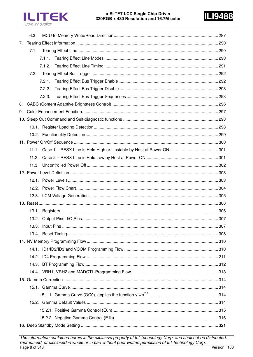
6.3. MCU to Memory Write/Read Direction ......................................................................................... 287
7. Tearing Effect Information ......................................................................................................................... 290
7.1. Tearing Effect Line ........................................................................................................................ 290
7.1.1. Tearing Effect Line Modes ................................................................................................. 290
7.1.2. Tearing Effect Line Timing ................................................................................................. 291
7.2. Tearing Effect Bus Trigger ............................................................................................................ 292
7.2.1. Tearing Effect Bus Trigger Enable ..................................................................................... 292
7.2.2. Tearing Effect Bus Trigger Disable .................................................................................... 293
7.2.3. Tearing Effect Bus Trigger Sequences .............................................................................. 293
8. CABC (Content Adaptive Brightness Control) ........................................................................................... 296
9. Color Enhancement Function .................................................................................................................... 297
10. Sleep Out Command and Self-diagnostic functions ................................................................................. 298
10.1. Register Loading Detection .......................................................................................................... 298
10.2. Functionality Detection ................................................................................................................. 299
11. Power On/Off Sequence ........................................................................................................................... 300
11.1. Case 1 – RESX Line is Held High or Unstable by Host at Power ON ......................................... 301
11.2. Case 2 – RESX Line is Held Low by Host at Power ON.............................................................. 301
11.3. Uncontrolled Power Off ................................................................................................................ 302
12. Power Level Definition............................................................................................................................... 303
12.1. Power Levels ................................................................................................................................ 303
12.2. Power Flow Chart ......................................................................................................................... 304
12.3. LCM Voltage Generation .............................................................................................................. 305
13. Reset ......................................................................................................................................................... 306
13.1. Registers ...................................................................................................................................... 306
13.2. Output Pins, I/O Pins .................................................................................................................... 307
13.3. Input Pins ..................................................................................................................................... 307
13.4. Reset Timing ................................................................................................................................ 308
14. NV Memory Programming Flow ................................................................................................................ 310
14.1. ID1/ID2/ID3 and VCOM Programming Flow ................................................................................ 310
14.2. ID4 Programming Flow ................................................................................................................ 311
14.3. BT Programming Flow .................................................................................................................. 312
14.4. VRH1, VRH2 and MADCTL Programming Flow .......................................................................... 313
15. Gamma Correction .................................................................................................................................... 314
15.1. Gamma Curve .............................................................................................................................. 314
15.1.1. Gamma Curve (GC0), applies the function y = x2.2 ........................................................... 314
15.2. Gamma Default Values ................................................................................................................ 314
15.2.1. Positive Gamma Control (E0h) .......................................................................................... 315
15.2.2. Negative Gamma Control (E1h) ........................................................................................ 316
16. Deep Standby Mode Setting ..................................................................................................................... 321
The information contained herein is the exclusive property of ILI Technology Corp. and shall not be distributed,
reproduced, or disclosed in whole or in part without prior written permission of ILI Technology Corp.
Page 8 of 343
Version: 100
�



 V2版本原理图(Capacitive-Fingerprint-Reader-Schematic_V2).pdf
 摄像头工作原理.doc
 VL53L0X简要说明(En.FLVL53L00216).pdf
 原理图(DVK720-Schematic).pdf
 原理图(Pico-Clock-Green-Schdoc).pdf
 原理图(RS485-CAN-HAT-B-schematic).pdf
 File:SIM7500_SIM7600_SIM7800 Series_SSL_Application Note_V2.00.pdf
 ADS1263(Ads1262).pdf
 原理图(Open429Z-D-Schematic).pdf
 用户手册(Capacitive_Fingerprint_Reader_User_Manual_CN).pdf
 CY7C68013A(英文版)(CY7C68013A).pdf
 TechnicalReference_Dem.pdf