I
Q
M
8
6
5
8
C
—
6
D
I
n
e
r
t
i
a
l
M
e
a
s
u
r
e
m
e
n
t
U
n
i
t
w
i
t
h
M
o
t
i
o
n
C
o
-
P
r
o
c
e
s
s
o
r
ADVANCE INFORMATION — CONFIDENTIAL AND PROPRIETARY — DO NOT DISTRIBUTE
QMI8658C DATASHEET
SEPTEMBER 10, 2021
© 2021 QST Corporation
QMI8658C • Rev 0.8
www. qstcorp.com
QST SOLUTIONS LIMITED
120 BAYTECH DR, SAN JOSE, CA 95134
�
I
Q
M
8
6
5
8
C
—
6
D
I
n
e
r
t
i
a
l
M
e
a
s
u
r
e
m
e
n
t
U
n
i
t
w
i
t
h
M
o
t
i
o
n
C
o
-
P
r
o
c
e
s
s
o
r
ADVANCE INFORMATION — CONFIDENTIAL AND PROPRIETARY — DO NOT DISTRIBUTE
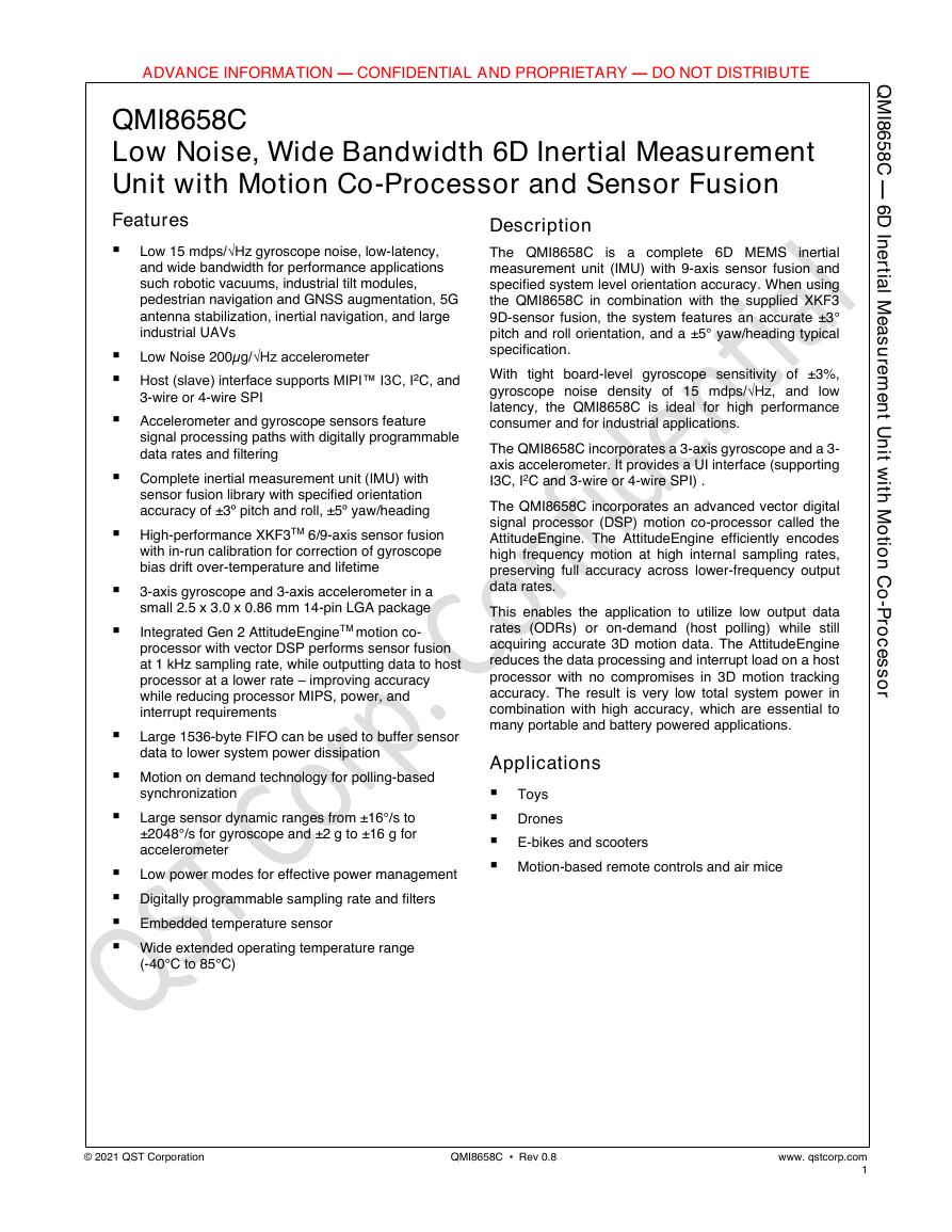
QMI8658C
Low Noise, Wide Bandwidth 6D Inertial Measurement
Unit with Motion Co-Processor and Sensor Fusion
Features
Description
▪ Low 15 mdps/√Hz gyroscope noise, low-latency,
and wide bandwidth for performance applications
such robotic vacuums, industrial tilt modules,
pedestrian navigation and GNSS augmentation, 5G
antenna stabilization, inertial navigation, and large
industrial UAVs
▪ Low Noise 200µg/√Hz accelerometer
▪ Host (slave) interface supports MIPI™ I3C, I2C, and
3-wire or 4-wire SPI
▪ Accelerometer and gyroscope sensors feature
signal processing paths with digitally programmable
data rates and filtering
▪ Complete inertial measurement unit (IMU) with
sensor fusion library with specified orientation
accuracy of ±3º pitch and roll, ±5º yaw/heading
▪ High-performance XKF3TM 6/9-axis sensor fusion
with in-run calibration for correction of gyroscope
bias drift over-temperature and lifetime
▪ 3-axis gyroscope and 3-axis accelerometer in a
small 2.5 x 3.0 x 0.86 mm 14-pin LGA package
▪
Integrated Gen 2 AttitudeEngineTM motion co-
processor with vector DSP performs sensor fusion
at 1 kHz sampling rate, while outputting data to host
processor at a lower rate – improving accuracy
while reducing processor MIPS, power, and
interrupt requirements
▪ Large 1536-byte FIFO can be used to buffer sensor
data to lower system power dissipation
▪ Motion on demand technology for polling-based
synchronization
▪ Large sensor dynamic ranges from ±16°/s to
±2048°/s for gyroscope and ±2 g to ±16 g for
accelerometer
▪ Low power modes for effective power management
▪ Digitally programmable sampling rate and filters
▪ Embedded temperature sensor
▪ Wide extended operating temperature range
(-40°C to 85°C)
is a complete 6D MEMS
The QMI8658C
inertial
measurement unit (IMU) with 9-axis sensor fusion and
specified system level orientation accuracy. When using
the QMI8658C in combination with the supplied XKF3
9D-sensor fusion, the system features an accurate ±3°
pitch and roll orientation, and a ±5° yaw/heading typical
specification.
With tight board-level gyroscope sensitivity of ±3%,
gyroscope noise density of 15 mdps/√Hz, and low
latency, the QMI8658C is ideal for high performance
consumer and for industrial applications.
The QMI8658C incorporates a 3-axis gyroscope and a 3-
axis accelerometer. It provides a UI interface (supporting
I3C, I2C and 3-wire or 4-wire SPI) .
The QMI8658C incorporates an advanced vector digital
signal processor (DSP) motion co-processor called the
AttitudeEngine. The AttitudeEngine efficiently encodes
high frequency motion at high internal sampling rates,
preserving full accuracy across lower-frequency output
data rates.
This enables the application to utilize low output data
rates (ODRs) or on-demand (host polling) while still
acquiring accurate 3D motion data. The AttitudeEngine
reduces the data processing and interrupt load on a host
processor with no compromises in 3D motion tracking
accuracy. The result is very low total system power in
combination with high accuracy, which are essential to
many portable and battery powered applications.
Applications
▪ Toys
▪ Drones
▪ E-bikes and scooters
▪ Motion-based remote controls and air mice
© 2021 QST Corporation
QMI8658C • Rev 0.8
www. qstcorp.com
1
�
I
Q
M
8
6
5
8
C
—
6
D
I
n
e
r
t
i
a
l
M
e
a
s
u
r
e
m
e
n
t
U
n
i
t
w
i
t
h
M
o
t
i
o
n
C
o
-
P
r
o
c
e
s
s
o
r
1
ADVANCE INFORMATION — CONFIDENTIAL AND PROPRIETARY — DO NOT DISTRIBUTE
Table of Contents
General Information ...................................................................................................... 4
Ordering Information .........................................................................................................4
Marking Information ..........................................................................................................4
Internal Block Diagram .......................................................................................................5
Interface Operating Modes ................................................................................................6
Application Diagrams .........................................................................................................7
Package & Pin Information .................................................................................................9
Recommended External Components ............................................................................... 11
1.1
1.2
1.3
1.4
1.5
1.6
1.7
2 QMI8658C Architecture ................................................................................................ 12
AttitudeEngine Mode Overview ....................................................................................... 12
Advantages of the Attitude Engine Approach .................................................................... 12
9D Sensor Fusion and Auto-Calibration using XKF3 ........................................................... 13
Frames of Reference and Conventions for Using QMI8658C .............................................. 14
2.1
2.2
2.3
2.4
3
3.1
3.2
3.3
3.4
3.5
3.6
3.7
System, Electrical and Electro-Mechanical Characteristics ............................................. 15
Absolute Maximum Ratings ............................................................................................. 15
Recommended Operating Conditions ............................................................................... 15
System Level Specifications .............................................................................................. 16
Electro-Mechanical Specifications..................................................................................... 17
Accelerometer Programmable Characteristics ................................................................... 19
Gyroscope Programmable Characteristics ......................................................................... 21
Electrical Characteristics ................................................................................................... 22
Current Consumption ............................................................................................................ 22
Temperature Sensor ........................................................................................................ 24
3.8
4
Register Map Overview ................................................................................................ 25
UI Register Map Overview ................................................................................................ 25
4.1
5.1
5.2
5.3
5.4
5.5
5.6
5.7
5.8
5.9
5 UI Sensor Configuration Settings and Output Data ........................................................ 28
Typical Sensor Mode Configuration and Output Data ........................................................ 28
AttitudeEngine (AE) Mode Configuration and Output Data ................................................ 29
General Purpose Register ................................................................................................. 29
Configuration Registers .................................................................................................... 30
FIFO Registers .................................................................................................................. 34
Status and Time Stamp Registers ...................................................................................... 35
Sensor Data Output Registers ........................................................................................... 37
Reset register................................................................................................................... 40
CTRL 9 Functionality (Executing Pre-defined Commands) .................................................. 40
CTRL 9 Description ................................................................................................................ 40
WCtrl9 (Write – CTRL9 Protocol) ........................................................................................... 40
Ctrl9R (CTRL9 Protocol - Read) .............................................................................................. 41
Ctrl9 (CTRL9 Protocol Acknowledge) .................................................................................... 41
CTRL9 Commands in Detail ................................................................................................... 42
6
6.1
Interrupts .................................................................................................................... 44
Overview ......................................................................................................................... 44
Interrupt 1 (INT1) .................................................................................................................. 44
Interrupt 2 (INT2) .................................................................................................................. 44
7 Operating Modes ......................................................................................................... 45
© 2021 QST Corporation
QMI8658C • Rev 0.8
www. qstcorp.com
2
�
I
Q
M
8
6
5
8
C
—
6
D
I
n
e
r
t
i
a
l
M
e
a
s
u
r
e
m
e
n
t
U
n
i
t
w
i
t
h
M
o
t
i
o
n
C
o
-
P
r
o
c
e
s
s
o
r
8
9
ADVANCE INFORMATION — CONFIDENTIAL AND PROPRIETARY — DO NOT DISTRIBUTE
7.1
7.2
General Mode Transitioning ............................................................................................. 48
Transition Times .............................................................................................................. 48
FIFO Description ........................................................................................................... 49
Using the FIFO ................................................................................................................. 49
FIFO Register Description ................................................................................................. 50
8.1
8.2
Performing Device Self Test .......................................................................................... 51
Accelerometer Self Test ................................................................................................... 51
Gyroscope Self Test .......................................................................................................... 51
9.1
9.2
10.1
10 Host Serial Interface ..................................................................................................... 52
Serial Peripheral Interface (SPI) ........................................................................................ 52
SPI Timing Characteristics ................................................................................................. 57
I2C Interface ..................................................................................................................... 59
10.2
10.3 MIPI I3C Interface ............................................................................................................ 60
11 Package and Handling .................................................................................................. 61
Package Drawing ............................................................................................................. 61
Reflow Specification......................................................................................................... 62
Storage Specifications ...................................................................................................... 62
11.1
11.2
11.3
12 Document Information ................................................................................................. 63
Revision History ............................................................................................................... 63
12.1
© 2021 QST Corporation
QMI8658C • Rev 0.8
www. qstcorp.com
3
�
I
Q
M
8
6
5
8
C
—
6
D
I
n
e
r
t
i
a
l
M
e
a
s
u
r
e
m
e
n
t
U
n
i
t
w
i
t
h
M
o
t
i
o
n
C
o
-
P
r
o
c
e
s
s
o
r
ADVANCE INFORMATION — CONFIDENTIAL AND PROPRIETARY — DO NOT DISTRIBUTE
1 General Information
1.1 Ordering Information
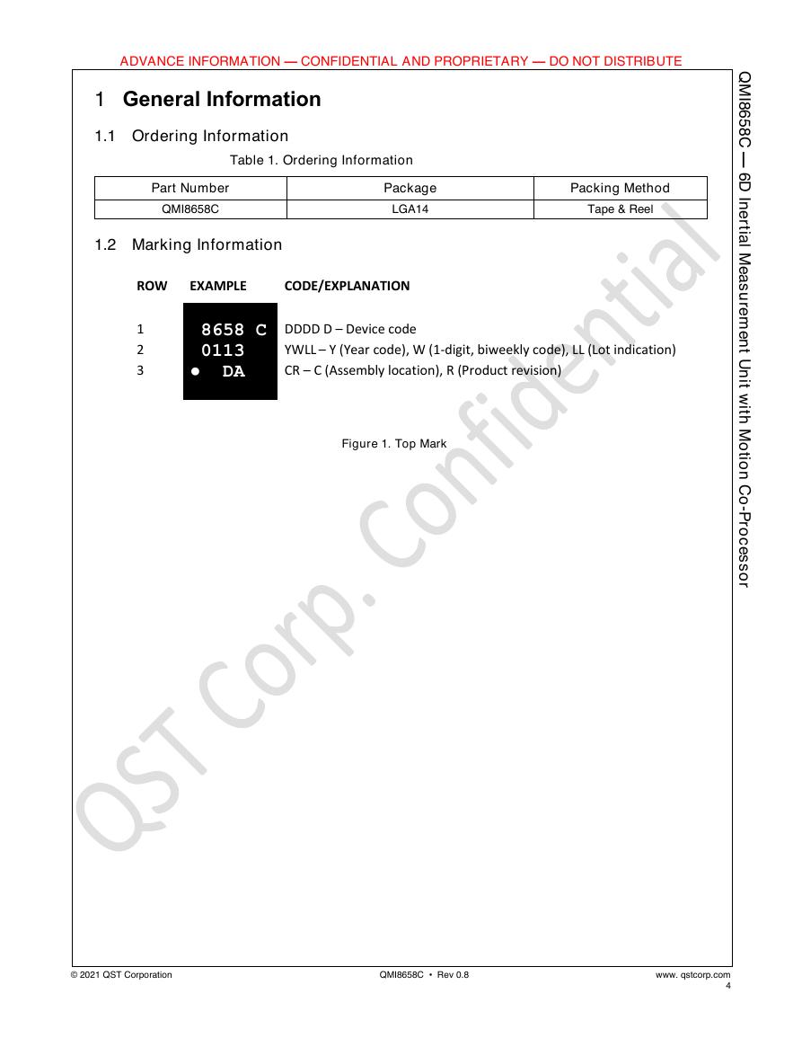
Table 1. Ordering Information
Part Number
QMI8658C
1.2 Marking Information
Package
LGA14
ROW
EXAMPLE
CODE/EXPLANATION
Packing Method
Tape & Reel
1
2
3
8658 C DDDD D – Device code
0113
● DA
YWLL – Y (Year code), W (1-digit, biweekly code), LL (Lot indication)
CR – C (Assembly location), R (Product revision)
Figure 1. Top Mark
© 2021 QST Corporation
QMI8658C • Rev 0.8
www. qstcorp.com
4
�
I
Q
M
8
6
5
8
C
—
6
D
I
n
e
r
t
i
a
l
M
e
a
s
u
r
e
m
e
n
t
U
n
i
t
w
i
t
h
M
o
t
i
o
n
C
o
-
P
r
o
c
e
s
s
o
r
ADVANCE INFORMATION — CONFIDENTIAL AND PROPRIETARY — DO NOT DISTRIBUTE
1.3
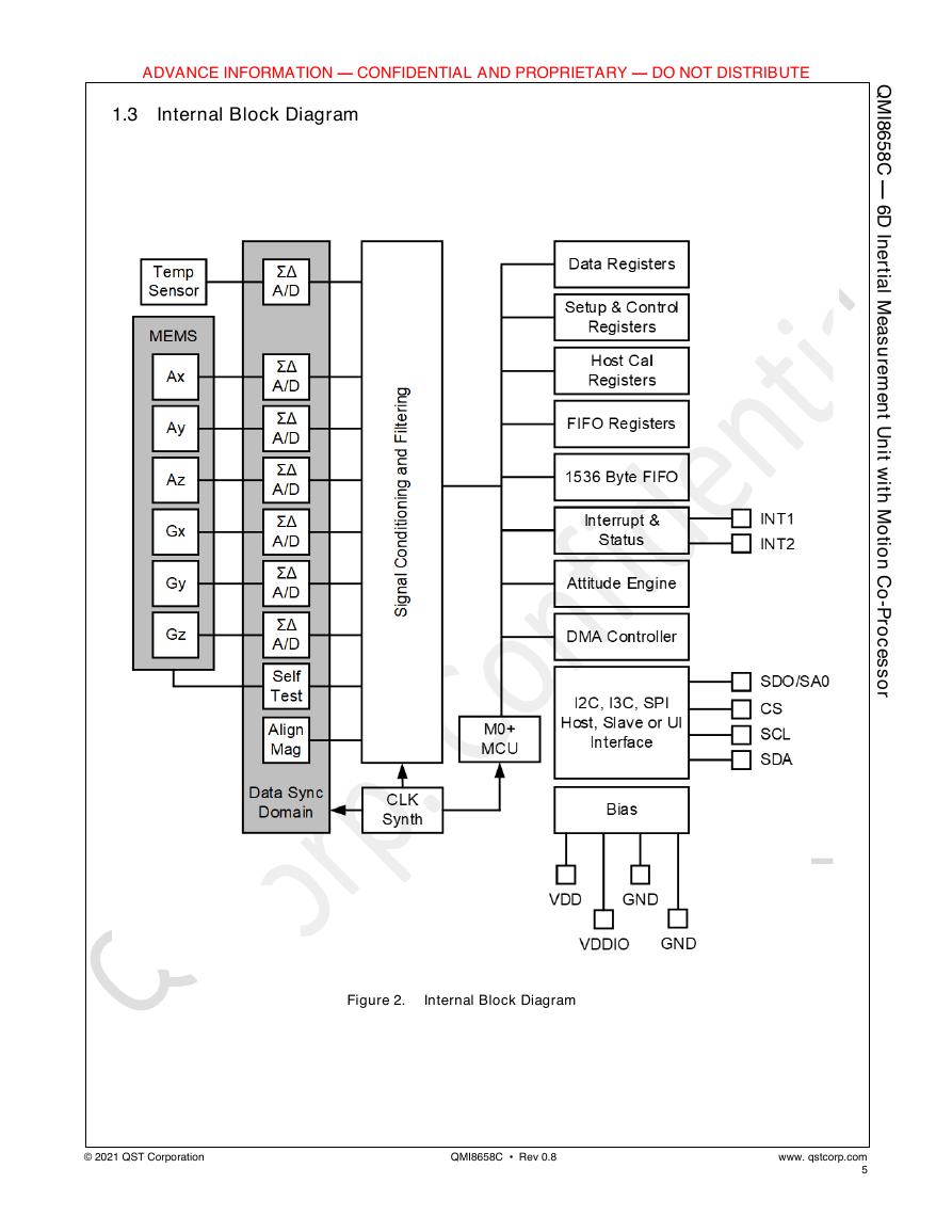
Internal Block Diagram
Figure 2.
Internal Block Diagram
© 2021 QST Corporation
QMI8658C • Rev 0.8
www. qstcorp.com
5
�
I
Q
M
8
6
5
8
C
—
6
D
I
n
e
r
t
i
a
l
M
e
a
s
u
r
e
m
e
n
t
U
n
i
t
w
i
t
h
M
o
t
i
o
n
C
o
-
P
r
o
c
e
s
s
o
r
ADVANCE INFORMATION — CONFIDENTIAL AND PROPRIETARY — DO NOT DISTRIBUTE
1.4
Interface Operating Modes
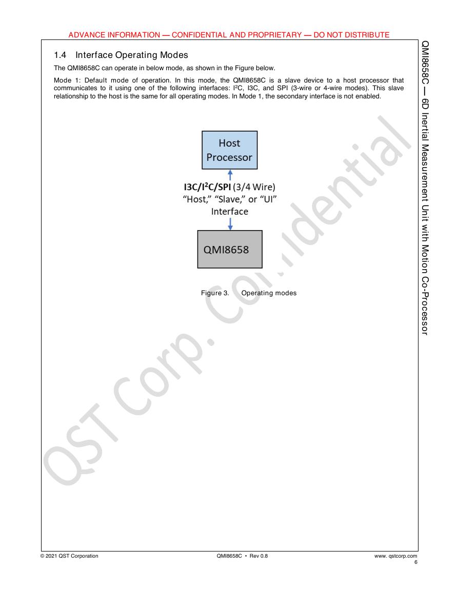
The QMI8658C can operate in below mode, as shown in the Figure below.
Mode 1: Default mode of operation. In this mode, the QMI8658C is a slave device to a host processor that
communicates to it using one of the following interfaces: I2C, I3C, and SPI (3-wire or 4-wire modes). This slave
relationship to the host is the same for all operating modes. In Mode 1, the secondary interface is not enabled.
Figure 3. Operating modes
© 2021 QST Corporation
QMI8658C • Rev 0.8
www. qstcorp.com
6
�
I
Q
M
8
6
5
8
C
—
6
D
I
n
e
r
t
i
a
l
M
e
a
s
u
r
e
m
e
n
t
U
n
i
t
w
i
t
h
M
o
t
i
o
n
C
o
-
P
r
o
c
e
s
s
o
r
ADVANCE INFORMATION — CONFIDENTIAL AND PROPRIETARY — DO NOT DISTRIBUTE
1.5 Application Diagrams
The typical application diagrams are shown in this section.
Figure 4.
4-Wire SPI-UI mode
Figure 5.
3-Wire SPI-UI mode
© 2021 QST Corporation
QMI8658C • Rev 0.8
www. qstcorp.com
7
�




 V2版本原理图(Capacitive-Fingerprint-Reader-Schematic_V2).pdf
 摄像头工作原理.doc
 VL53L0X简要说明(En.FLVL53L00216).pdf
 原理图(DVK720-Schematic).pdf
 原理图(Pico-Clock-Green-Schdoc).pdf
 原理图(RS485-CAN-HAT-B-schematic).pdf
 File:SIM7500_SIM7600_SIM7800 Series_SSL_Application Note_V2.00.pdf
 ADS1263(Ads1262).pdf
 原理图(Open429Z-D-Schematic).pdf
 用户手册(Capacitive_Fingerprint_Reader_User_Manual_CN).pdf
 CY7C68013A(英文版)(CY7C68013A).pdf
 TechnicalReference_Dem.pdf