mxchipWNetTM-DTU
Advanced settings
13110
MXCHIP All rights reserved�
Agenda
• UART data’s integrity
• UART frame control
• Power save management
• TCP maintenance settings
• Multiple AP roaming and dual mode
• Firmware update mode, MFG mode
13110
MXCHIP All rights reserved�
mxchipWNetTM-DTU
UART data’s integrity
13110
MXCHIP All rights reserved�
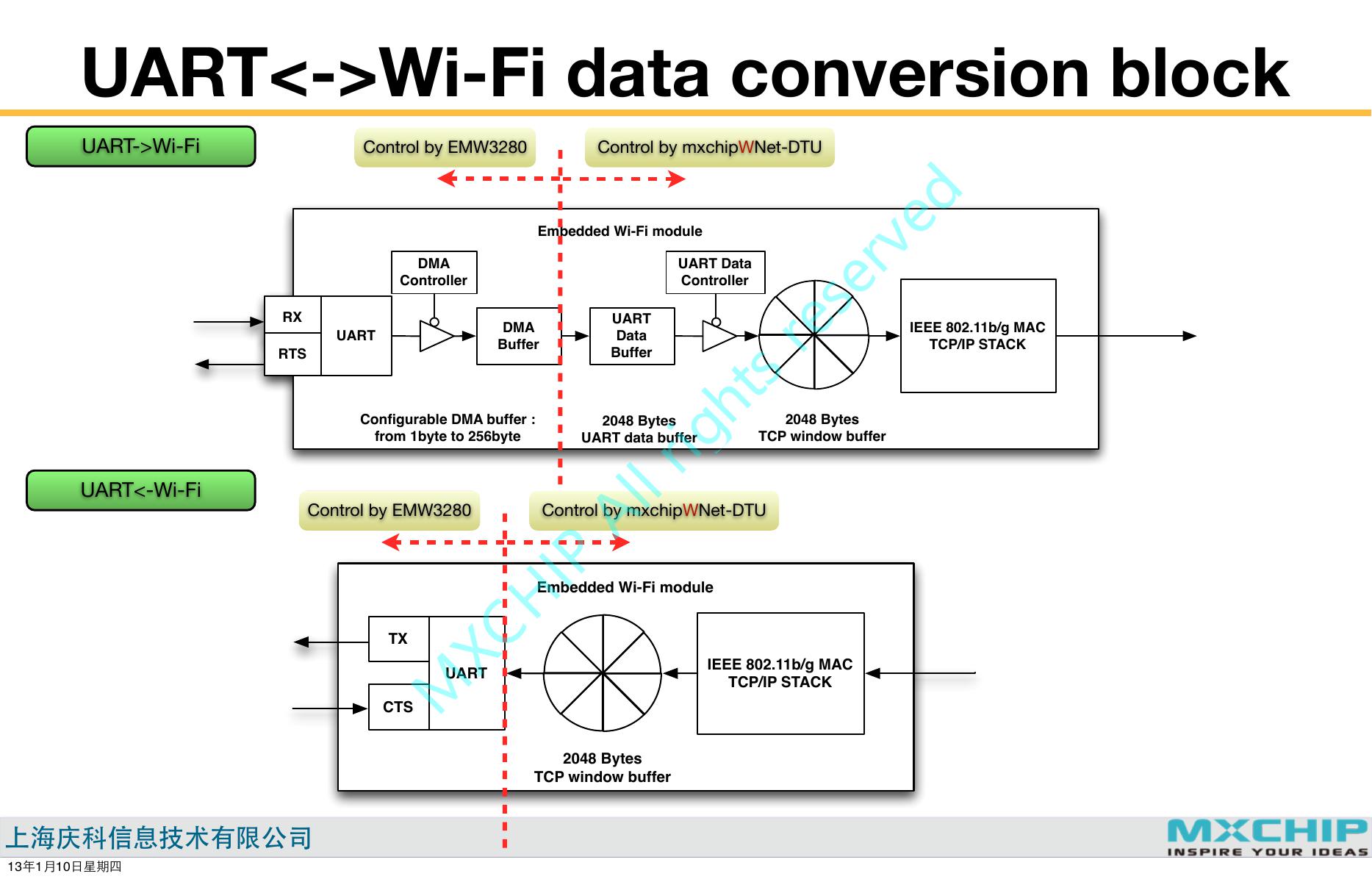
UART<->Wi-Fi data conversion block
UART->Wi-Fi
Control by EMW3280
Control by mxchipWNet-DTU
Embedded Wi-Fi module
DMA
Controller
UART Data
Controller
RX
RTS
UART
DMA
Buffer
UART
Data
Buffer
IEEE 802.11b/g MAC
TCP/IP STACK
Configurable DMA buffer :
from 1byte to 256byte
2048 Bytes
UART data buffer
2048 Bytes
TCP window buffer
UART<-Wi-Fi
Control by EMW3280
Control by mxchipWNet-DTU
Embedded Wi-Fi module
IEEE 802.11b/g MAC
TCP/IP STACK
TX
CTS
UART
2048 Bytes
TCP window buffer
13110
MXCHIP All rights reserved�
Related settings in UART->Wi-Fi
UART->Wi-Fi
Embedded Wi-Fi module
DMA
Controller
UART Data
Controller
RX
RTS
UART
DMA
Buffer
UART
Data
Buffer
IEEE 802.11b/g MAC
TCP/IP STACK
Configurable DMA buffer :
from 1byte to 256byte
2048 Bytes
UART data buffer
2048 Bytes
TCP window buffer
UART settings
Purpose: Set UART working parameters
Possible settings:
Baud rate; data length; parity method;
CTS/RTS ...
Purpose: reduce the CPU time spending
DMA buffer size
when receiving UART data
UART->WiFi conversion
Purpose: Set different methods that
convert UART data to network package
Possible settings:
No buffer; 8 Bytes; 16bytes; 32 bytes; 64
bytes; 128 bytes; 256 bytes
Possible settings:
Data flow mode; Time stamp mode; Data
package mode, Auto frame mode...
13110
MXCHIP All rights reserved�
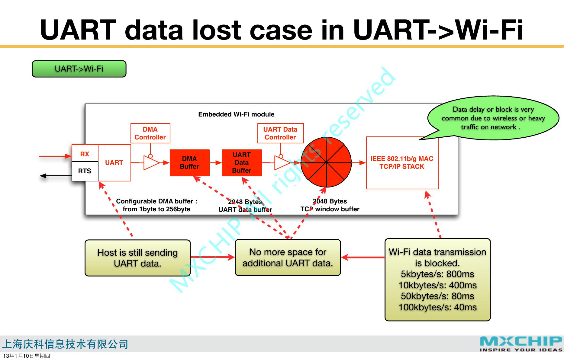
UART data lost case in UART->Wi-Fi
UART->Wi-Fi
Embedded Wi-Fi module
DMA
Controller
UART Data
Controller
Data delay or block is very
common due to wireless or heavy
traffic on network .
RX
RTS
UART
DMA
Buffer
UART
Data
Buffer
IEEE 802.11b/g MAC
TCP/IP STACK
Configurable DMA buffer :
from 1byte to 256byte
2048 Bytes
UART data buffer
2048 Bytes
TCP window buffer
Host is still sending
UART data.
No more space for
additional UART data.
13110
Wi-Fi data transmission
is blocked.
5kbytes/s: 800ms
10kbytes/s: 400ms
50kbytes/s: 80ms
100kbytes/s: 40ms
MXCHIP All rights reserved�
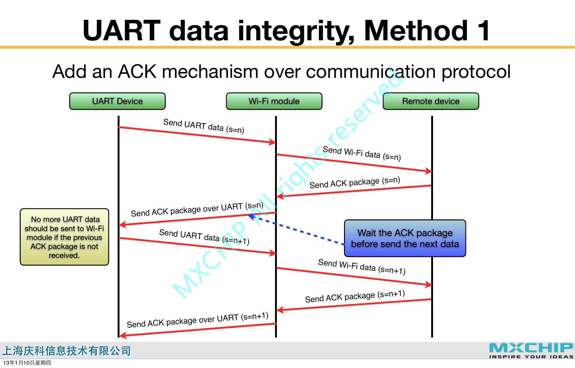
UART data integrity, Method 1
Add an ACK mechanism over communication protocol
UART Device
Wi-Fi module
Remote device
Send UART data (s=n)
Send Wi-Fi data (s=n)
Send ACK package (s=n)
Wait the ACK package
before send the next data
Send Wi-Fi data (s=n+1)
Send ACK package (s=n+1)
No more UART data
should be sent to Wi-Fi
module if the previous
ACK package is not
received.
Send ACK package over UART (s=n)
Send UART data (s=n+1)
Send ACK package over UART (s=n+1)
13110
MXCHIP All rights reserved�
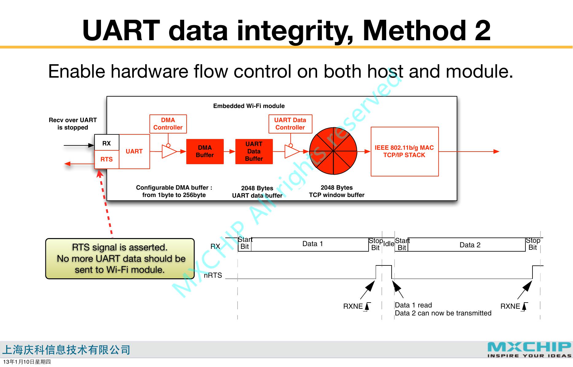
UART data integrity, Method 2
Enable hardware flow control on both host and module.
Universal synchronous asynchronous receiver transmitter (USART)
Embedded Wi-Fi module
RM0008
Recv over UART
is stopped
DMA
Controller
RTS flow control
UART Data
Controller
RX
RTS
UART
UART
Data
Buffer
DMA
Buffer
If the RTS flow control is enabled (RTSE=1), then nRTS is asserted (tied low) as long as the
USART receiver is ready to receive new data. When the receive register is full, nRTS is
deasserted, indicating that the transmission is expected to stop at the end of the current
frame. Figure 299 shows an example of communication with RTS flow control enabled.
IEEE 802.11b/g MAC
TCP/IP STACK
Configurable DMA buffer :
from 1byte to 256byte
2048 Bytes
UART data buffer
2048 Bytes
TCP window buffer
Figure 299. RTS flow control
RTS signal is asserted.
No more UART data should be
sent to Wi-Fi module.
RX
Start
Bit
Data 1
Stop
Bit
IdleStart
Bit
Data 2
Stop
Bit
nRTS
CTS flow control
RXNE
Data 1 read
Data 2 can now be transmitted
RXNE
13110
If the CTS flow control is enabled (CTSE=1), then the transmitter checks the nCTS input
MXCHIP All rights reserved�




 V2版本原理图(Capacitive-Fingerprint-Reader-Schematic_V2).pdf
 摄像头工作原理.doc
 VL53L0X简要说明(En.FLVL53L00216).pdf
 原理图(DVK720-Schematic).pdf
 原理图(Pico-Clock-Green-Schdoc).pdf
 原理图(RS485-CAN-HAT-B-schematic).pdf
 File:SIM7500_SIM7600_SIM7800 Series_SSL_Application Note_V2.00.pdf
 ADS1263(Ads1262).pdf
 原理图(Open429Z-D-Schematic).pdf
 用户手册(Capacitive_Fingerprint_Reader_User_Manual_CN).pdf
 CY7C68013A(英文版)(CY7C68013A).pdf
 TechnicalReference_Dem.pdf