ST7789V2
Datasheet
Sitronix reserves the right to change the contents in this document
without prior notice, please contact Sitronix to obtain the latest
version of datasheet before placing your order. No responsibility is
assumed by Sitronix for any infringement of patent or other rights
of third parties which may result from its use.
2016 Sitronix Technology Corporation. All rights reserved.
Version 1.0
2016/11
�
ST7789V2
LIST OF CONTENT
1
2
3
4
5
6
GENERAL DESCRIPTION ................................................................................................................................. 12
FEATURES ............................................................................................................................................................ 13
PAD ARRANGEMENT ........................................................................................................................................ 15
3.1
3.2
3.3
3.4
OUTPUT BUMP DIMENSION ............................................................................................................................. 15
INPUT BUMP DIMENSION ................................................................................................................................ 16
ALIGNMENT MARK DIMENSION ..................................................................................................................... 17
CHIP INFORMATION ........................................................................................................................................ 17
PAD CENTER COORDINATES ......................................................................................................................... 18
BLOCK DIAGRAM ............................................................................................................................................. 31
PIN DESCRIPTION ............................................................................................................................................. 32
6.1
6.2
6.3
6.4
POWER SUPPLY PINS ....................................................................................................................................... 32
INTERFACE LOGIC PINS .................................................................................................................................. 33
DRIVER OUTPUT PINS ..................................................................................................................................... 36
TEST AND OTHER PINS .................................................................................................................................... 36
7
DRIVER ELECTRICAL CHARACTERISTICS .............................................................................................. 37
7.1
7.2
7.3
7.4
ABSOLUTE OPERATION RANGE ....................................................................................................................... 37
DC CHARACTERISTICS ................................................................................................................................... 38
POWER CONSUMPTION ................................................................................................................................... 40
AC CHARACTERISTICS ................................................................................................................................... 41
7.4.1
8080 Series MCU Parallel Interface Characteristics: 18/16/9/8-bit Bus ................................................. 41
7.4.2
Serial Interface Characteristics (3-line serial): ........................................................................................ 43
7.4.3
Serial Interface Characteristics (4-line serial): ........................................................................................ 44
7.4.4
RGB Interface Characteristics: ................................................................................................................ 46
7.4.5
Reset Timing: ............................................................................................................................................ 48
8
FUNCTION DESCRIPTION ............................................................................................................................... 50
8.1
8.2
MPU INTERFACE TYPE SELECTION ................................................................................................................ 50
8080-Ⅰ SERIES MCU PARALLEL INTERFACE ................................................................................................ 51
8.2.1 Write cycle sequence ................................................................................................................................. 51
8.2.2
Read cycle sequence ................................................................................................................................. 52
8.3
8.4
8080-Ⅱ SERIES MCU PARALLEL INTERFACE ................................................................................................ 54
SERIAL INTERFACE ......................................................................................................................................... 55
8.4.1
Pin description .......................................................................................................................................... 55
8.4.2 Command write mode ............................................................................................................................... 56
Version 1.0 Page 2 of 319 2016/11
Sitronix Confidential The information contained herein is the exclusive property of Sitronix and shall not be distributed, reproduced, or
disclosed in whole or in part without prior written permission of Sitronix.
�
ST7789V2
Read function ............................................................................................................................................ 58
8.4.3
8.4.4
3-line serial interface Ⅰ/Ⅱ protocol ...................................................................................................... 58
8.4.5
4-line serial protocol ................................................................................................................................. 60
8.4.6
2 data lane serial Interface ....................................................................................................................... 62
8.5
8.6
DATA TRANSFER BREAK AND RECOVERY ....................................................................................................... 66
DATA TRANSFER PAUSE .................................................................................................................................. 68
8.6.1
Parallel interface pause ............................................................................................................................ 68
8.7
DATA TRANSFER MODE .................................................................................................................................. 68
8.7.1 Method 1 ................................................................................................................................................... 68
8.7.2 Method 2 ................................................................................................................................................... 69
8.8
DATA COLOR CODING ..................................................................................................................................... 70
8.8.1
8080-Ⅰ series 8-bit Parallel Interface .................................................................................................... 70
8.8.2
8-bit data bus for 12-bit/pixel (RGB 4-4-4-bit input), 4K-Colors, 3Ah=”03h”........................................ 70
8.8.3
8-bit data bus for 16-bit/pixel (RGB 5-6-5-bit input), 65K-Colors, 3Ah=”05h”...................................... 71
8.8.4
8-bit data bus for 18-bit/pixel (RGB-6-6-6-bit input), 262K-Colors, 3Ah=”06h” ................................... 72
8.8.5
8080-Ⅱ series 8-bit Parallel Interface .................................................................................................... 73
8.8.6
8-bit data bus for 16-bit/pixel (RGB 5-6-5-bit input), 65K-Colors, 3Ah=”05h”...................................... 73
8.8.7
8-bit data bus for 18-bit/pixel (RGB 6-6-6-bit input), 262K-Colors, 3Ah=”06h”.................................... 74
8.8.8
8080-Ⅰ series 16-Bit Parallel Interface.................................................................................................. 75
8.8.9
16-bit data bus for 12-bit/pixel (RGB 4-4-4-bit input), 4K-Colors, 3Ah=”03h”...................................... 76
8.8.10
16-bit data bus for 16-bit/pixel (RGB 5-6-5-bit input) 65K-Color, 3Ah=”05h” .................................. 77
8.8.11 16-bit data bus for 18-bit/pixel (RGB-6-6-6-bit input), 262K-Colors, 3Ah=”06h”, MDT[1:0]=”00b” . 78
8.8.12
16-bit data bus for 18-bit/pixel (RGB-6-6-6-bit input), 262K-Colors, 3Ah=”06h”, MDT[1:0]=”01b”
79
8.8.13
16-bit data bus for 18-bit/pixel (RGB-6-6-6-bit input), 262K-Colors, 3Ah=”06h”, MDT[1:0]=”10b”
80
8.8.14
16-bit data bus for 18-bit/pixel (RGB-6-6-6-bit input), 262K-Colors, 3Ah=”06h”, MDT[1:0]=”11b”
8.8.15
8.8.16
8.8.17
81
8080-Ⅱ series 16-Bit Parallel Interface ............................................................................................. 82
16-bit data bus for 16-bit/pixel (RGB 5-6-5-bit input) 65K-Color, 3Ah=”05h” .................................. 82
16-bit data bus for 18-bit/pixel (RGB-6-6-6-bit input), 262K-Colors, 3Ah=”06h”, MDT[1:0]=”00b”
83
8.8.18
16-bit data bus for 18-bit/pixel (RGB-6-6-6-bit input), 262K-Colors, 3Ah=”06h”, MDT[1:0]=”01b”
84
8.8.19
16-bit data bus for 18-bit/pixel (RGB-6-6-6-bit input), 262K-Colors, 3Ah=”06h”, MDT[1:0]=”10b”
84
8.8.20
16-bit data bus for 18-bit/pixel (RGB-6-6-6-bit input), 262K-Colors, 3Ah=”06h”, MDT[1:0]=”11b”
86
Version 1.0 Page 3 of 319 2016/11
Sitronix Confidential The information contained herein is the exclusive property of Sitronix and shall not be distributed, reproduced, or
disclosed in whole or in part without prior written permission of Sitronix.
�
ST7789V2
8080-Ⅰ series 9-Bit Parallel Interface ............................................................................................... 87
Write 9-bit data for RGB 5-6-5-bit input (65K-Color), 3Ah=”05h”.................................................... 87
Write 9-bit data for RGB 6-6-6-bit input (262K-Color), 3Ah=”06h”, MDT[1:0]=”00b” .................. 88
Write 9-bit data for RGB 6-6-6-bit input (262K-Color), 3Ah=”06h”, MDT[1:0]=”01b” .................. 89
8080-Ⅱ series 9-bit Parallel Interface ............................................................................................... 90
Write 9-bit data for RGB 5-6-5-bit input (65K-Color), 3Ah=”05h”.................................................... 90
Write 9-bit data for RGB 6-6-6-bit input (262K-Color), 3Ah=”06h”, MDT[1:0]=”00b” .................. 91
Write 9-bit data for RGB 6-6-6-bit input (262K-Color), 3Ah=”06h”, MDT[1:0]=”01b” .................. 92
8080-Ⅰ series 18-Bit Parallel Interface ............................................................................................. 93
18-bit data bus for 12-bit/pixel (RGB-4-4-4-bit input), 4K-colors, 3Ah=”03h” ................................. 94
18-bit data bus for 16-bit/pixel (RGB-5-6-5-bit input), 65K-colors, 3Ah=”05h” ............................... 95
18-bit data bus for 18-bit/pixel (RGB-6-6-6-bit input), 262K-colors, 3Ah=”06h” ............................. 97
8080-Ⅱ series 18-Bit Parallel Interface ............................................................................................. 98
18-bit data bus for 16-bit/pixel (RGB-5-6-5-bit input), 65K-colors, 3Ah=”05h” ............................... 99
18-bit data bus for 18-bit/pixel (RGB-6-6-6-bit input), 262K-colors, 3Ah=”06h” ........................... 101
3-Line Serial Interface ....................................................................................................................... 102
Write data for 12-bit/pixel (RGB-4-4-4 bit input), 4K-Colors, 3Ah=”03h” ...................................... 102
Write data for 16-bit/pixel (RGB 5-6-5-bit input), 65K-Colors, 3Ah=”05h” .................................... 103
Write data for 18-bit/pixel (RGB-6-6-6-bit input), 262K-Colors, 3Ah=”06h” .................................. 103
2 Data Lane Serial Interface .............................................................................................................. 104
Write data for 12-bit/pixel (RGB 4-4-4-bit input), 4K-Colors, 3Ah=”03h” ...................................... 104
Write data for 16-bit/pixel (RGB 5-6-5-bit input), 65K-Colors, 3Ah=”05h” .................................... 105
Write data for 18-bit/pixel (RGB 6-6-6-bit input), 262K-Colors, 3Ah=”06h” .................................. 105
4-Line Serial Interface ....................................................................................................................... 106
Write data for 12-bit/pixel (RGB 4-4-4-bit input), 4K-Colors, 3Ah=”03h” ...................................... 106
Write data for 16-bit/pixel (RGB-5-6-5-bit input), 65K-Colors, 3Ah=”05h” .................................... 107
Write data for 18-bit/pixel (RGB-6-6-6-bit input), 262K-Colors, 3Ah=”06h” .................................. 108
8.8.21
8.8.22
8.8.23
8.8.24
8.8.25
8.8.26
8.8.27
8.8.28
8.8.29
8.8.30
8.8.31
8.8.32
8.8.33
8.8.34
8.8.35
8.8.36
8.8.37
8.8.38
8.8.39
8.8.40
8.8.41
8.8.42
8.8.43
8.8.44
8.8.45
8.8.46
8.8.47
8.9
RGB INTERFACE ........................................................................................................................................... 109
8.9.1
RGB interface Selection .......................................................................................................................... 109
8.9.2
RGB Color Format ................................................................................................................................. 109
8.9.3
RGB Interface Definition ........................................................................................................................ 115
8.9.4
RGB Interface Mode Selection ................................................................................................................ 116
8.9.5
RGB Interface Timing ............................................................................................................................. 116
8.10
VSYNC INTERFACE ..................................................................................................................................... 120
8.10.1
8.10.2
18-bit RGB Interface .......................................................................................................................... 120
VSYNC Interface Mode ...................................................................................................................... 122
8.11
DISPLAY DATA RAM .................................................................................................................................... 124
8.11.1
Configuration ..................................................................................................................................... 124
Version 1.0 Page 4 of 319 2016/11
Sitronix Confidential The information contained herein is the exclusive property of Sitronix and shall not be distributed, reproduced, or
disclosed in whole or in part without prior written permission of Sitronix.
�
ST7789V2
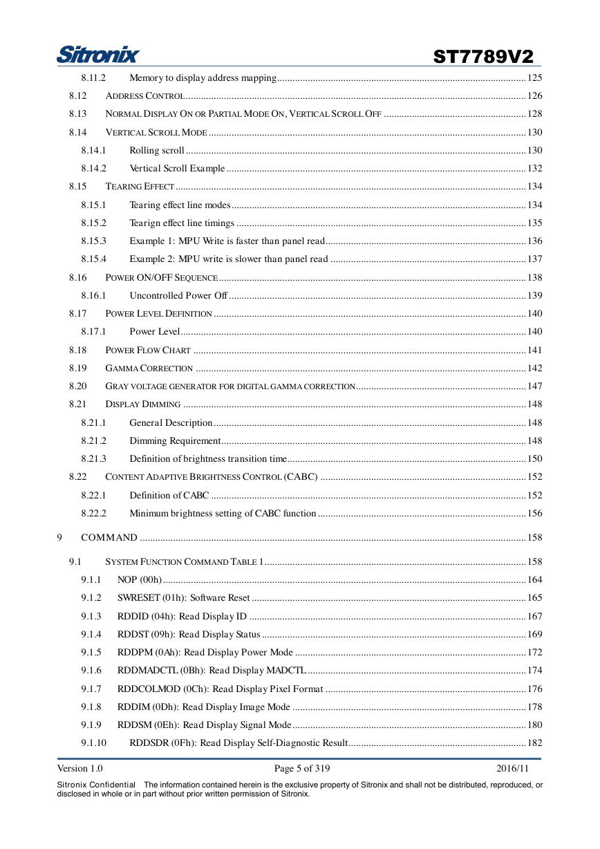
Memory to display address mapping .................................................................................................. 125
8.11.2
8.12
8.13
8.14
ADDRESS CONTROL ...................................................................................................................................... 126
NORMAL DISPLAY ON OR PARTIAL MODE ON, VERTICAL SCROLL OFF ........................................................ 128
VERTICAL SCROLL MODE ............................................................................................................................. 130
8.14.1
8.14.2
Rolling scroll ...................................................................................................................................... 130
Vertical Scroll Example ...................................................................................................................... 132
8.15
TEARING EFFECT .......................................................................................................................................... 134
8.15.1
8.15.2
8.15.3
8.15.4
Tearing effect line modes .................................................................................................................... 134
Tearign effect line timings .................................................................................................................. 135
Example 1: MPU Write is faster than panel read............................................................................... 136
Example 2: MPU write is slower than panel read ............................................................................. 137
8.16
POWER ON/OFF SEQUENCE ......................................................................................................................... 138
8.16.1
Uncontrolled Power Off ..................................................................................................................... 139
8.17
POWER LEVEL DEFINITION ........................................................................................................................... 140
8.17.1
Power Level........................................................................................................................................ 140
8.18
8.19
8.20
8.21
POWER FLOW CHART ................................................................................................................................... 141
GAMMA CORRECTION .................................................................................................................................. 142
GRAY VOLTAGE GENERATOR FOR DIGITAL GAMMA CORRECTION ................................................................... 147
DISPLAY DIMMING ....................................................................................................................................... 148
8.21.1
8.21.2
8.21.3
General Description ........................................................................................................................... 148
Dimming Requirement ........................................................................................................................ 148
Definition of brightness transition time.............................................................................................. 150
8.22
CONTENT ADAPTIVE BRIGHTNESS CONTROL (CABC) ................................................................................. 152
8.22.1
8.22.2
Definition of CABC ............................................................................................................................ 152
Minimum brightness setting of CABC function .................................................................................. 156
9
COMMAND ........................................................................................................................................................ 158
9.1
SYSTEM FUNCTION COMMAND TABLE 1 ....................................................................................................... 158
9.1.1 NOP (00h) ............................................................................................................................................... 164
9.1.2
SWRESET (01h): Software Reset ............................................................................................................ 165
9.1.3
RDDID (04h): Read Display ID ............................................................................................................. 167
9.1.4
RDDST (09h): Read Display Status ........................................................................................................ 169
9.1.5
RDDPM (0Ah): Read Display Power Mode ........................................................................................... 172
9.1.6
RDDMADCTL (0Bh): Read Display MADCTL ...................................................................................... 174
9.1.7
RDDCOLMOD (0Ch): Read Display Pixel Format ............................................................................... 176
9.1.8
RDDIM (0Dh): Read Display Image Mode ............................................................................................ 178
9.1.9
RDDSM (0Eh): Read Display Signal Mode ............................................................................................ 180
9.1.10
RDDSDR (0Fh): Read Display Self-Diagnostic Result ...................................................................... 182
Version 1.0 Page 5 of 319 2016/11
Sitronix Confidential The information contained herein is the exclusive property of Sitronix and shall not be distributed, reproduced, or
disclosed in whole or in part without prior written permission of Sitronix.
�
ST7789V2
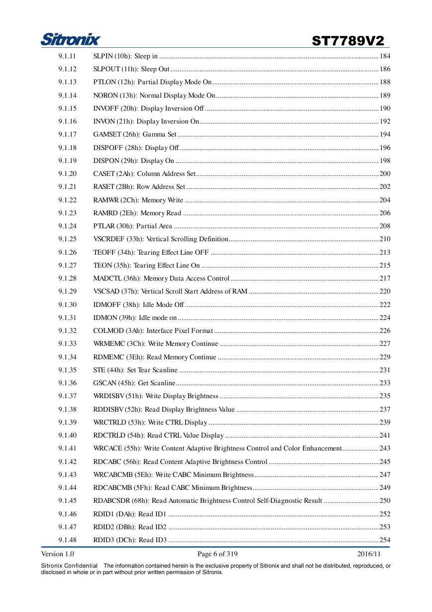
SLPIN (10h): Sleep in ........................................................................................................................ 184
SLPOUT (11h): Sleep Out .................................................................................................................. 186
PTLON (12h): Partial Display Mode On ........................................................................................... 188
NORON (13h): Normal Display Mode On ......................................................................................... 189
INVOFF (20h): Display Inversion Off ............................................................................................... 190
INVON (21h): Display Inversion On .................................................................................................. 192
GAMSET (26h): Gamma Set .............................................................................................................. 194
DISPOFF (28h): Display Off ............................................................................................................. 196
DISPON (29h): Display On ............................................................................................................... 198
CASET (2Ah): Column Address Set .................................................................................................... 200
RASET (2Bh): Row Address Set ......................................................................................................... 202
RAMWR (2Ch): Memory Write .......................................................................................................... 204
RAMRD (2Eh): Memory Read ........................................................................................................... 206
PTLAR (30h): Partial Area ................................................................................................................ 208
VSCRDEF (33h): Vertical Scrolling Definition .................................................................................. 210
TEOFF (34h): Tearing Effect Line OFF ............................................................................................ 213
TEON (35h): Tearing Effect Line On ................................................................................................. 215
MADCTL (36h): Memory Data Access Control ................................................................................. 217
VSCSAD (37h): Vertical Scroll Start Address of RAM ....................................................................... 220
IDMOFF (38h): Idle Mode Off .......................................................................................................... 222
IDMON (39h): Idle mode on .............................................................................................................. 224
COLMOD (3Ah): Interface Pixel Format .......................................................................................... 226
WRMEMC (3Ch): Write Memory Continue ....................................................................................... 227
RDMEMC (3Eh): Read Memory Continue ........................................................................................ 229
STE (44h): Set Tear Scanline ............................................................................................................. 231
GSCAN (45h): Get Scanline ............................................................................................................... 233
WRDISBV (51h): Write Display Brightness ....................................................................................... 235
RDDISBV (52h): Read Display Brightness Value .............................................................................. 237
WRCTRLD (53h): Write CTRL Display ............................................................................................. 239
RDCTRLD (54h): Read CTRL Value Display .................................................................................... 241
WRCACE (55h): Write Content Adaptive Brightness Control and Color Enhancement .................... 243
RDCABC (56h): Read Content Adaptive Brightness Control ............................................................ 245
WRCABCMB (5Eh): Write CABC Minimum Brightness .................................................................... 247
RDCABCMB (5Fh): Read CABC Minimum Brightness..................................................................... 249
RDABCSDR (68h): Read Automatic Brightness Control Self-Diagnostic Result .............................. 250
RDID1 (DAh): Read ID1 ................................................................................................................... 252
RDID2 (DBh): Read ID2 ................................................................................................................... 253
RDID3 (DCh): Read ID3 ................................................................................................................... 254
9.1.11
9.1.12
9.1.13
9.1.14
9.1.15
9.1.16
9.1.17
9.1.18
9.1.19
9.1.20
9.1.21
9.1.22
9.1.23
9.1.24
9.1.25
9.1.26
9.1.27
9.1.28
9.1.29
9.1.30
9.1.31
9.1.32
9.1.33
9.1.34
9.1.35
9.1.36
9.1.37
9.1.38
9.1.39
9.1.40
9.1.41
9.1.42
9.1.43
9.1.44
9.1.45
9.1.46
9.1.47
9.1.48
Version 1.0 Page 6 of 319 2016/11
Sitronix Confidential The information contained herein is the exclusive property of Sitronix and shall not be distributed, reproduced, or
disclosed in whole or in part without prior written permission of Sitronix.
�
ST7789V2
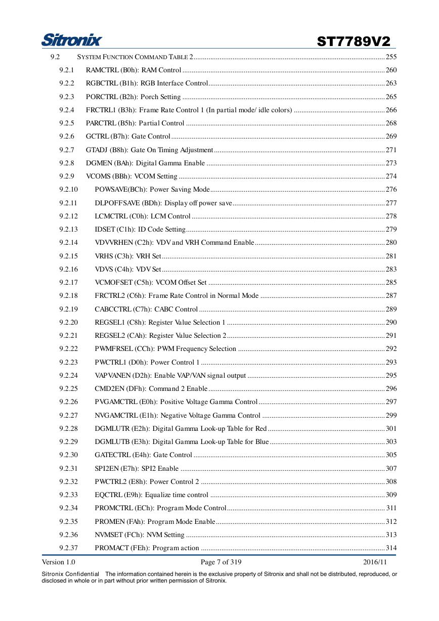
SYSTEM FUNCTION COMMAND TABLE 2 ....................................................................................................... 255
9.2
9.2.1
RAMCTRL (B0h): RAM Control ............................................................................................................. 260
9.2.2
RGBCTRL (B1h): RGB Interface Control............................................................................................... 263
9.2.3
PORCTRL (B2h): Porch Setting ............................................................................................................. 265
9.2.4
FRCTRL1 (B3h): Frame Rate Control 1 (In partial mode/ idle colors) ................................................. 266
9.2.5
PARCTRL (B5h): Partial Control ........................................................................................................... 268
9.2.6 GCTRL (B7h): Gate Control ................................................................................................................... 269
9.2.7 GTADJ (B8h): Gate On Timing Adjustment ............................................................................................ 271
9.2.8 DGMEN (BAh): Digital Gamma Enable ................................................................................................ 273
9.2.9
VCOMS (BBh): VCOM Setting ............................................................................................................... 274
9.2.10
9.2.11
9.2.12
9.2.13
9.2.14
9.2.15
9.2.16
9.2.17
9.2.18
9.2.19
9.2.20
9.2.21
9.2.22
9.2.23
9.2.24
9.2.25
9.2.26
9.2.27
9.2.28
9.2.29
9.2.30
9.2.31
9.2.32
9.2.33
9.2.34
9.2.35
9.2.36
9.2.37
POWSAVE(BCh): Power Saving Mode .............................................................................................. 276
DLPOFFSAVE (BDh): Display off power save .................................................................................. 277
LCMCTRL (C0h): LCM Control ........................................................................................................ 278
IDSET (C1h): ID Code Setting ........................................................................................................... 279
VDVVRHEN (C2h): VDV and VRH Command Enable ...................................................................... 280
VRHS (C3h): VRH Set ........................................................................................................................ 281
VDVS (C4h): VDV Set ........................................................................................................................ 283
VCMOFSET (C5h): VCOM Offset Set ............................................................................................... 285
FRCTRL2 (C6h): Frame Rate Control in Normal Mode ................................................................... 287
CABCCTRL (C7h): CABC Control .................................................................................................... 289
REGSEL1 (C8h): Register Value Selection 1 ..................................................................................... 290
REGSEL2 (CAh): Register Value Selection 2 ..................................................................................... 291
PWMFRSEL (CCh): PWM Frequency Selection ............................................................................... 292
PWCTRL1 (D0h): Power Control 1 ................................................................................................... 293
VAPVANEN (D2h): Enable VAP/VAN signal output .......................................................................... 295
CMD2EN (DFh): Command 2 Enable ............................................................................................... 296
PVGAMCTRL (E0h): Positive Voltage Gamma Control .................................................................... 297
NVGAMCTRL (E1h): Negative Voltage Gamma Control .................................................................. 299
DGMLUTR (E2h): Digital Gamma Look-up Table for Red ............................................................... 301
DGMLUTB (E3h): Digital Gamma Look-up Table for Blue .............................................................. 303
GATECTRL (E4h): Gate Control ....................................................................................................... 305
SPI2EN (E7h): SPI2 Enable .............................................................................................................. 307
PWCTRL2 (E8h): Power Control 2 ................................................................................................... 308
EQCTRL (E9h): Equalize time control .............................................................................................. 309
PROMCTRL (ECh): Program Mode Control ..................................................................................... 311
PROMEN (FAh): Program Mode Enable ........................................................................................... 312
NVMSET (FCh): NVM Setting ........................................................................................................... 313
PROMACT (FEh): Program action ................................................................................................... 314
Version 1.0 Page 7 of 319 2016/11
Sitronix Confidential The information contained herein is the exclusive property of Sitronix and shall not be distributed, reproduced, or
disclosed in whole or in part without prior written permission of Sitronix.
�
ST7789V2
10 APPLICATION ................................................................................................................................................... 315
10.1
10.2
10.3
10.4
CONFIGURATION OF POWER SUPPLY CIRCUIT ............................................................................................... 315
VOLTAGE GENERATION................................................................................................................................. 316
RELATIONSHIP ABOUT SOURCE VOLTAGE ...................................................................................................... 317
APPLIED VOLTAGE TO THE TFT PANEL ......................................................................................................... 318
11 REVISION HISTORY ........................................................................................................................................ 319
Version 1.0 Page 8 of 319 2016/11
Sitronix Confidential The information contained herein is the exclusive property of Sitronix and shall not be distributed, reproduced, or
disclosed in whole or in part without prior written permission of Sitronix.
�


 V2版本原理图(Capacitive-Fingerprint-Reader-Schematic_V2).pdf
 摄像头工作原理.doc
 VL53L0X简要说明(En.FLVL53L00216).pdf
 原理图(DVK720-Schematic).pdf
 原理图(Pico-Clock-Green-Schdoc).pdf
 原理图(RS485-CAN-HAT-B-schematic).pdf
 File:SIM7500_SIM7600_SIM7800 Series_SSL_Application Note_V2.00.pdf
 ADS1263(Ads1262).pdf
 原理图(Open429Z-D-Schematic).pdf
 用户手册(Capacitive_Fingerprint_Reader_User_Manual_CN).pdf
 CY7C68013A(英文版)(CY7C68013A).pdf
 TechnicalReference_Dem.pdf